1 minute read
Alternator Circuit and Cooling Fan


ALTERNATOR CIRCUIT AND COOLING FAN
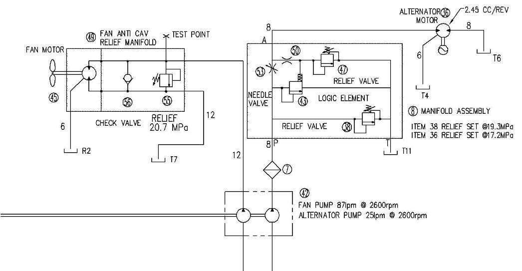
The auxiliary circuits for the cooling fan are supplied by a separate pump driven from the transmission, pressure relief is by a separate inline relief valve set at 17.2 MPa (2500 psi). The fan motor receives a constant flow of 79 lpm at 2600 RPM, hydraulic oil is supplied through the fan motor which then returns back to tank.
This supplies hydraulic oil to a manifold assembly which houses a logic element that controls a flow of 19 lpm for the alternator motor RPM control. Internally there are two relief valve set at 17.2 PMa (2500 psi).
Hydraulic oil is supplied through the alternator motor and then back to tank.
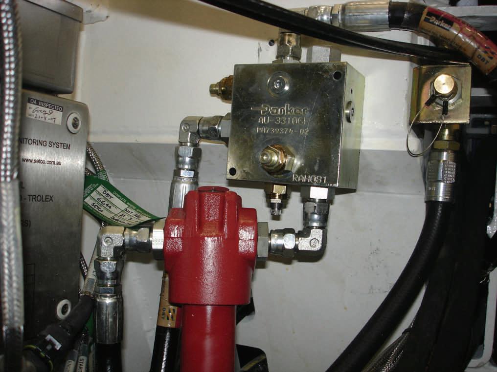
Manifold Assembly
Filter