2 minute read
Safety Precautions


Each working section of the valve bank is fitted with 22.4 MPa (3250 psi) port reliefs. The working sections of the main hydraulic valve bank control; lift and tilt (lift arms), the winch and attachments which are fitted to PTO. These are pilot activated via a four-way joystick control lever for the lift and tilt. The winch system and PTO attachments are controlled by 2 two-way hydraulic control levers. Relief pressure is via a separate inline port relief valves and the main relief valve all situated in the valve bank.
Auxiliary Circuits
The auxiliary circuits for the cooling fan are supplied by a separate pump driven from the transmission, pressure relief is by a separate inline relief valve set at 17.2 MPa (2500 psi). The fan motor receives a constant flow of 79 lpm at 2600 RPM. Hydraulic oil is supplied through the fan motor which then returns back to tank.
The auxiliary circuit for the alternator motor is supplied by a gear pump piggybacked on the cooling fan pump. This supplied hydraulic oil to a manifold assembly which houses a logic element that controls a flow of 19 lpm for the alternator motor RPM control. Internally there are two relief valves set at 17.2 MPa (2500 psi).
SAFETY PRECAUTIONS
All personnel performing maintenance tasks on this machine should have been trained, assessed and be deemed competent. They should be appointed by the mine management.
The following safety precautions are not intended to be exhaustive. Safe work practices should be used when servicing or operating heavy machinery.
ALWAYS give the engine an opportunity to cool down before performing servicing around the rear frame as engine components around this location are hot and could cause burns or scalding.
ALWAYS be aware of, and isolate, other forms of energy and pinch points (fan, belts, pulleys and drive lines) when accessing the engine compartment including pneumatic stored pressure, engine coolant pressure, hydraulic oil pressure and other heat sources such as engine block and exhaust system components.
ALWAYS install the articulation lock when accessing the machine articulation area as machine articulation will result in crush injuries.
ALWAYS install the lift arm lock when access underneath the lift arm assembly is required. Remove any attachments before raising and locking the lift arm assembly.
NEVER assume that all forms of energy have been isolated unless you have confirmed for yourself.
HYDRAULIC ISOLATION
To isolate the hydraulic system perform the following procedure:
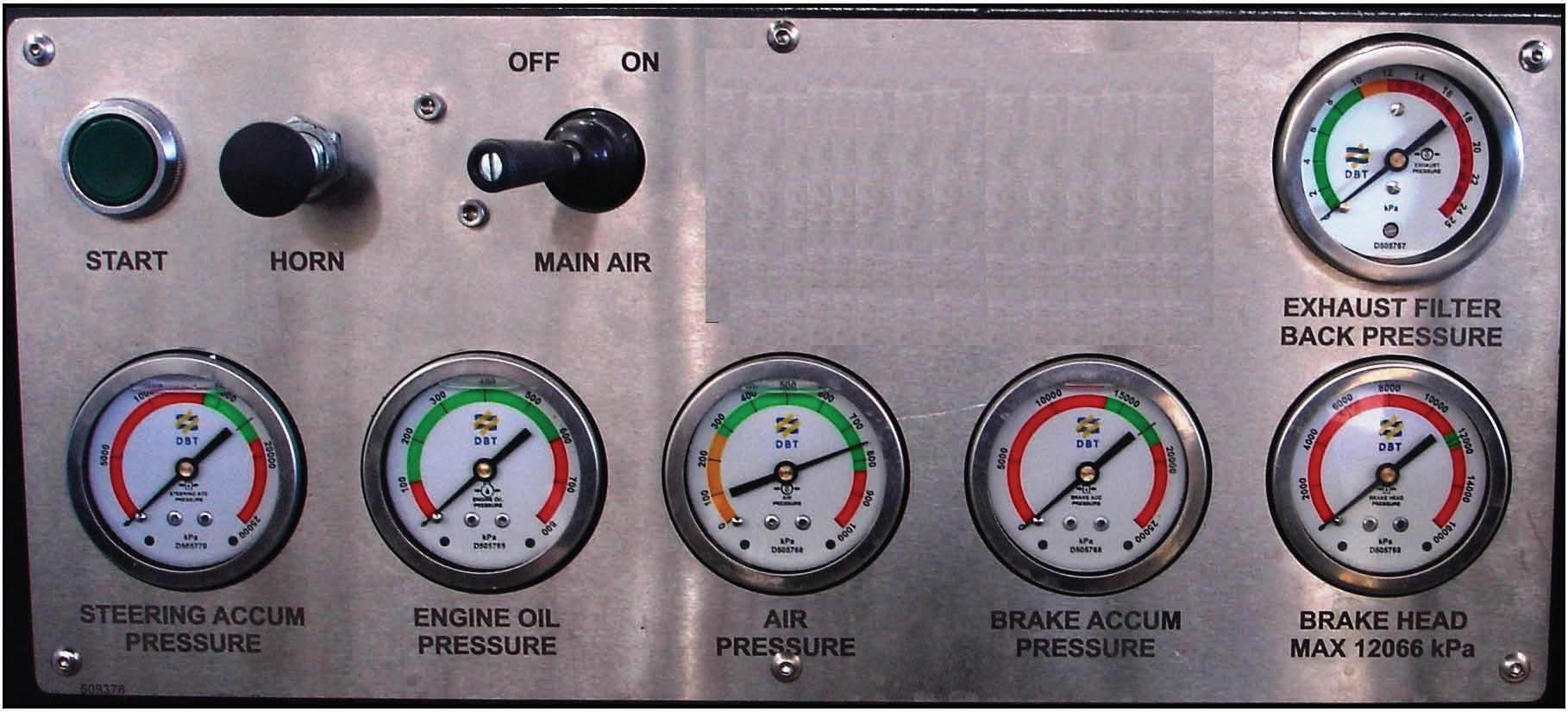
1. Ensure the area is clear of any obstruction and area is fit for carrying out safe operation and maintenance. 2. Lower the lift arms to the ground, shutdown the engine, fit a danger tag to the on/off toggle switch, connect the articulation lock and chock the wheels. 3. Depress the attachment quick connects button located in the operator's compartment. This will remove any residual pressure stored in the PTO lines. 4. Observe both steering and brake pressure gauges located in the operator's compartment. The hydraulic system features a steering and brake accumulator automatic dump off which removes hydraulic pressure from both accumulators once the engine and main air has been stopped. This is immediate. This is done by an air pilot from the air circuit. 5. Remove hydraulic tank pre-charge pressure (50 kPa) by cracking hydraulic tank filler cap.
Steering Accumulator Pressure Gauge Brake Accumulator Pressure Gauge