1 minute read
Attachment Controls Control Levers


CONTROL LEVERS
Three separate control levers are provided in the operator’s compartment. These controls operate the machine lift and tilt functions and PTO lines.
The four-way joystick control lever operates the machine’s lift and tilt functions. The lever has five positions tilt back, tilt forward, lift, lower and a hold. The lever is spring centred to the hold position.
The No. 1 and No. 2 two-way hydraulic control levers operate the PTO lines and the winch. These levers have three positions and are spring centred to the hold position. The oil pressure for these controls is supplied from the main control manifold at a pressure of 650 psi.
No. 1 - Two-Way Hydraulic Control Lever
Two-Way Control Levers
No. 2 - Two-Way Hydraulic Control Lever

Four-Way Joystick Control Lever
Maintenance
Inspections are to be carried out on the four-way joystick and two-way control levers as per Preventative Maintenance Inspection Schedules.
1. Inspect the control lever boots for damage. 2. Inspect operational performance.
Replace any worn or damaged parts and retest the operation of the machine or system.

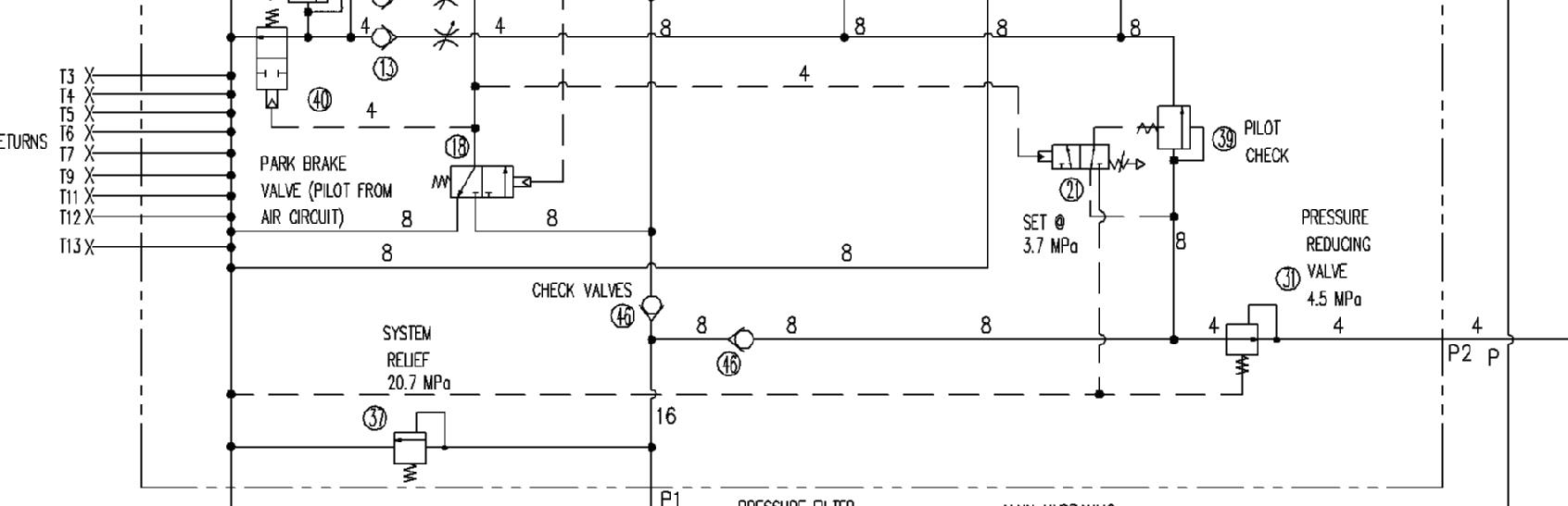
Pressure Reducing Valve Set at 650 PSI
Pilot Pressure Supply to Pilot Control Valves Set at 650 PSI
Lift Arm Control Valve No 1 RAS Valve

No 2 RAS Valve