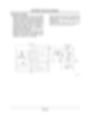
SYSTEM / Electrical System Starter Relay 2 Operation • When the key switch is turned to the START position, continuity between terminals B and ACC in the key switch is found. Current is supplied to the base in transistor Tr3 through resistance R in the starter relay 2. Transistor Tr3 is turned ON and current is supplied to coil R in starter relay 1. Consequently, battery power is supplied to terminal S in the starter motor from starter relay 1 so that the starter is operated. • When the engine is started, the alternator begins charging and the pulse wave pattern of the frequency in proportion to the engine speed is output from terminal P in the alternator.
• When this frequency reaches 170 Hz (alternator rotation speed is 1700 r/min), transistor Tr3 is turned OFF as no current is supplied to the base in transistor Tr3. Current to coil R in starter relay 1 is stopped at this time so that the starter is turned OFF.
Alternator
Starter Switch B
R
R Starter Relay 2 L
L
R R
P
P
Starter Relay 1
S
Tr3
Battery
E
To Starter Motor Terminal S
T4FG-02-03-004
T2-3-12


