2 minute read
COMPONENT OPERATION / Control Valve


OVERLOAD RELIEF VALVE (WITH MAKE-UP FUNCTION)
The overload relief valves are provided with the circuits in the bottom and the rod sides of the bucket and in the bottom and the rod sides of the coupler (auxiliary). The overload relief valve controls pressure in each front attachment circuit in order not to rise abnormally when each front attachment is operated by external load. It also makes make-up operation by drawing oil from the hydraulic oil tank in order to prevent cavitation when pressure in the front attachment circuit decreases.
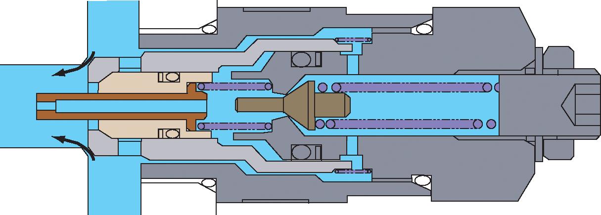
Bottom Side and Rod Side Circuits of Bucket Relief Operation
1. Pressure in port HP (front attachment circuit) acts on the pilot poppet through the orifice in the piston.
2. When pressure in port HP reaches the set force of spring B, the pilot poppet is opened, pressure oil from passage A flows to port LP (hydraulic oil tank) through the outer circumference of the sleeve.
3. At this time, a pressure difference occurs between port HP and the spring chamber due to the orifice.
4. When this pressure difference reaches the set force of spring A, the main poppet is opened and pressure oil from port HP flows to port LP.
5. Consequently, the pressure in Port HP (front attachment circuit) decreases.
6. When pressure in Port HP (front attachment circuit) decreases to the specified level, the piston and the main poppet are closed by the force of spring A.
The circuit in the bottom and the rod sides of the coupler (auxiliary) are also relieved in the same way.
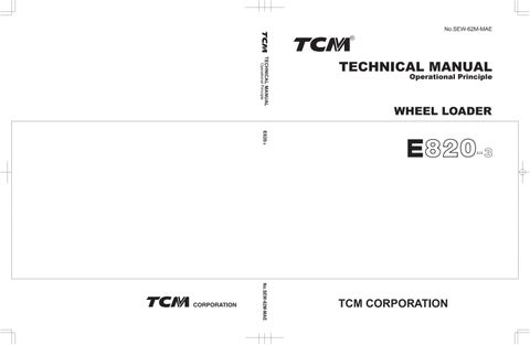
Make-Up Operation
1. When pressure in port HP (front attachment circuit) decreases lower than pressure in port LP (hydraulic oil tank), the sleeve moves to the right.
2. Hydraulic oil in port LP flows to port HP and cavitation is prevented.
3. When pressure in port HP increases more than the specified level, the sleeve is closed by the force of spring C.
T3-2-17
COMPONENT OPERATION / Control Valve

COMPONENT OPERATION / Control Valve
MAKE-UP VALVE
The make-up valve prevents cavitation in the lift arm lower circuit.
As for other cylinder circuits, cavitation is prevented by the make-up function of each overload relief valve.
Operation:
1. Pressure oil in port HP (actuator circuit) acts on spring chamber (4) through passage (2) in poppet (1). Therefore, pressure in port HP is equal to that in spring chamber (4).
2. Thereby, as pressure in port HP is high and the force to close poppet (1) (pressure in spring chamber (4) × pressure receiving area S2) is larger than the force to open poppet (1) (pressure at cylinder side × pressure receiving area S1), poppet (1) is closed.
3. When pressure in port HP is lower than that in port LP, the force to close poppet (1) is equal to the spring (3) force.
4. Thereby, when the force to open poppet (1) (pressure in port T × (pressure receiving area S2S1) is larger than the force to close poppet (1) (spring (3) force), poppet (1) is opened and hydraulic oil is supplied to port HP.
5. Therefore, cavitation in port HP is prevented.
In Operation
T3-2-19
(Blank)
COMPONENT OPERATION / Control Valve
T3-2-20