TMS800E OPERATOR’S MANUAL
SET-UP AND INSTALLATION b.
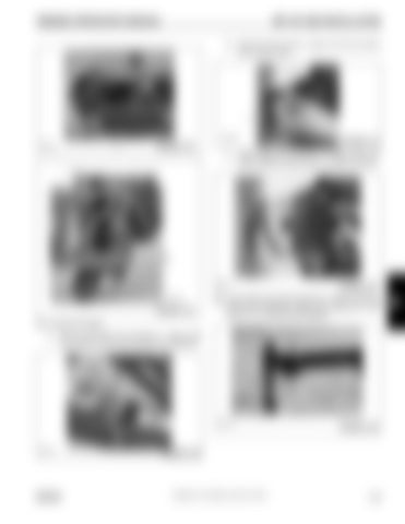
Remove dummy plug (1, Figure 4-27) from junction box on boom nose.
1 6642-20 6642-44
1
FIGURE 4-27
FIGURE 4-24 c.
Install cable end connector (1, Figure 4-28) from boom extension where dummy plug was removed.
1
1
6642-21 6642-45
FIGURE 4-25
FIGURE 4-28
20. Lower boom and remove tag line (1, Figure 4-29) from the tip of the extension. Figure 4-29 shows the 7 m (23 ft) and 10.1 m (33 ft) section together.
19. Connect LMI cables: a.
Remove LMI cable end connector (1, Figure 4-26) from extension and route through boom extension.
6642-22
1
FIGURE 4-29
1 6642-19
GROVE
FIGURE 4-26
Published 12-23-2008, Control # 132-03
4-15
4


