5 minute read
TMS800E OPERATOR’S MANUALSET-UP AND INSTALLATION


4. Insert the end of a wire rope into the socket, form a loop in the rope, and route the rope back through the socket allowing the “dead” end Figure 4-5 to protrude from the socket. Ensure the dead end of the rope is of sufficient length to apply end treatment to the dead end after the wedge has been seated.
5. Insert the wedge into the loop and pull the live end of the rope until the wedge and rope are snug inside the socket. It is recommended that the wedge be seated inside the socket to properly secure the wire rope by using the crane’s hoist to first apply a light load to the live line.
6. After final pin connections are made, increase the loads gradually until the wedge is properly seated.
7. The wire rope and wedge must be properly secured inside the socket before placing the crane into lifting service. It is the wedge that secures the wire rope inside the socket whereas the dead-end treatment is used to restrain the wedge from becoming dislodged from the socket should the rope suddenly become unloaded from the headache ball or hook block striking the ground, etc.
Sketches A through F Figure 4-6 illustrate various methods for treating the dead-ends of wire ropes which exit a wedge socket assembly. While use of the loop-back method is acceptable, care must be exercised to avoid the loop becoming entangled with tree branches and other components during crane transport and with the anti-two block system and other components during use of the crane.
Of the methods shown below, Grove prefers that method A or B or F be used on Grove cranes, i.e., clipping a short piece of wire rope to the dead-end or using a commercially available specialty clip or wedge. Typically, it is recommended that the tail length of the dead-end should be a minimum of 6 rope diameters but not less that 15.2 cm (6 in) for standard 6 to 8 strand ropes and 20 rope diameters but not less than 15.2 cm (6 in) for rotation resistant wire ropes.
When using method A, place a wire rope clip around the dead end by clamping a short extra piece of rope to the rope dead end. DO NOT CLAMP THE LIVE END. The U-bolt should bear against the dead end. The saddle of the clip should bear against the short extra piece. Torque the U-bolts according to the figures listed in the chart titled Wire Rope Clip Torque Values (Table 4-1).
Other sources for information with which crane users should be familiar and follow is provided by the American Society of Mechanical Engineers, American National Standard, ASME B30.5, latest revised. ASME (formerly ANSI) B30.5 applies to cableways, cranes, derricks, hoists, hooks, jacks, and slings. It states, in section 5-1.7.3, “(c) Swagged, compressed, or wedge socket fittings shall be applied as recommended by the rope, crane or fitting manufacture.” Wire ropes are addressed in ASME B30.5, section 5-1.7.2, ROPES, It states, in pertinent part, “(a) The ropes shall be of a construction recommended by the rope or crane manufacturer, or person qualified for that service.” Additional information is published by the Wire Rope Technical Board in the Wire Rope Users Manual, latest revised.
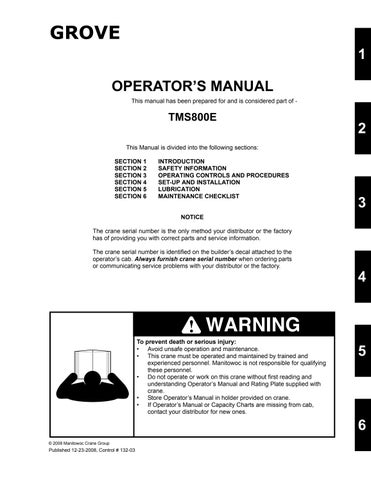
Upper Boom Nose Sheaves
Auxiliary Nose
To Main Hoist
9 PARTS LINE
Lower Boom Nose Sheaves
Removable Counterweight
Danger
Ensure that all mounting pins are properly installed and locked, during, and after operating the counterweight removal system.
• The 5443 kg (12,000 pound) removable counterweight consists of three slabs, each weighing 1814 kg (4000 pounds).
• The 8165 kg (18,000 pound) removable counterweight consists of three slabs each weighing 1814 kg (4000 pounds) and one slab weighing 2721 (6000 pounds).
• An optional 10,885 kg (24,000 pound) removal counterweight consists of two 1,360 kg (3000 pound) “wing weights” that hang on the existing 8,165 kg (18,000 pound) counterweight stack.
NOTE: This extra counterweight is not roadable due to the overall width of the machine when installed, but you can move around the jobsite with the full counterweight installed.
NOTE: The following procedures are applicable for removal and installation of any or all pieces Figure 4-8.
The counterweight contains lugs for attachment to the removal cylinders and lugs to pin it under the hoist mounting. The additional slabs pin the structure to each other. The counterweights can be pinned to the carrier deck and are transferred between the turntable and the carrier deck and by two hydraulic removal cylinders. The cylinders are controlled from a valve assembly located under the hoist mounting. The valve contains an inlet section, an outlet section with relief valve, and a working section for each cylinder. The valve is manually controlled by levers extending through the turntable side plates on each side.
Mounting The Counterweight
1. Position the crane on a firm level surface. Fully extend and set the outriggers.
2. Rotate and align the rear of the superstructure above the removable counterweight stowed on the carrier deck. Engaging the pin type turntable lock will aid alignment.
3. Using the counterweight removal control valve levers located on either side of the turntable, lower the counterweight cylinders. Pin the cylinders to the counterweight using the attach pins in the cylinders. Insert the retaining pins in the attach pins.
4. Push in, turn, and remove the long attach pins from the counterweight and carrier frame lugs.
5. Using the control levers, raise the counterweight up under the superstructure frame.
NOTE: It may be necessary to jog the counterweight removal control levers Figure 4-8 to install the upper attach pins.
6. Remove the upper attach pins from the stowage bushings and install them into the upper counterweight and superstructure frame lugs.
7. Push in on the pins and turn to lock pin in the notch.
8. Insert the long pins into the bottom of the counterweight. Push in on the pins and turn to lock pin in the notch.
9. The crane is now ready for operation with the counterweight installed.
Stowing The Counterweight
1. Position the crane on a firm level surface. Fully extend and set the outriggers.
2. Rotate the superstructure to align the counterweight with the stowage area. Engaging the pin type turntable lock will aid alignment.
NOTE: It may be necessary to jog the counterweight removal control levers to remove the weight of the counterweight from the upper attach pins.
3. Using the counterweight removal control valve levers, raise the counterweight cylinders to relieve weight on the upper attach pins. Push in, turn, and remove the upper attach pins from the superstructure frame lugs and the counterweight
4. Stow the upper attach pins in the bushings on the side of the superstructure.
5. Push in, turn, and remove the long pins from the bottom of the counterweight.
6. Using the removal control levers, slowly lower the counterweight onto the carrier stowage area.
7. Insert the long pins through the carrier lugs and counterweight. Push in and turn to lock pin in the notch.
8. Remove the attach pins from the counterweight lugs and cylinder ends. Raise the cylinders and stow the attach pins in cylinder and insert retainer clip pins.
9. The carrier is now ready for highway travel with the counterweight stowed.
ItemDescription
1Counterweight Removal Cylinder
2Spacer
3Bolt
4Washer
5Cylinder Attach Pin Assembly
6Capscrew
7Counterweight Weldment
8Nut
ItemDescription
9Counterweight Weldment (18,000# Only)
10Box Attach Pin
11Counterweight Weldment Attach Pin
12Hoist
13Turntable
14Counterweight Removal Valve Control Levers
15Counterweight Weld - LH (Optional)
16Counterweight Weld - RH (Optional)