14 minute read
TMS800E OPERATOR’S MANUALOPERATING CONTROLS AND PROCEDURES


Push the very top of the switch to activate the washer switch to spray washer fluid on the windshield.
Headlights Switch
The headlights switch (21) is a three position switch located on the bottom left side of the front console. The bottom position is off. The center position will illuminate marker, clearance and gauge lights. The top position will turn on the headlights in addition to the marker, clearance and gauge lights.
Beacon Light Switch (Optional)
The beacon light switch (19) is a two position, on-off switch located on the left side of the front console that controls the beacon light (42) on the top of the carrier cab.
Dimmer Switch
The dimmer switch (31) is located on the left bottom side of the front console. The switch controls the brightness of the gauge lights.
NOTE: The headlight switch (21) must be in the center or top position before gauge lights will illuminate and the dimmer switch becomes functional.
Headlights Dimmer Switch
The headlights dimmer switch (47) is incorporated in the turn signal switch. It is located on the left side of the steering column. The switch is activated by pulling or pushing the turn signal lever toward you or away from you.
Turn Signal Lever
The turn signal lever (47) is located on the steering column. Positioning the lever down causes the indicator light on the console and the left front and left rear signals to flash. Positioning the lever up causes the indicator light on the console and the right front and right rear signals to flash.
Cruise Control
The cruise control (47) is incorporated in the turn signal lever located on the left side of the steering column. Push the switch to ON to turn the cruise control on. Accelerate to desired speed and push (SET COAST) button on end of lever.
If cruise is stopped by braking and switch is still positioned to ON, the switch can be pushed to (RESUME-ACCEL) to resume cruise speed. Position switch to OFF to turn the cruise control off.
Hazard Light Switch
The hazard light switch (55) is located on the steering column. Pulling on the switch (in the direction of the arrow) causes all the turn signals and the indicator light on the console to flash.
Left Turn Signal Indicator
The left turn signal indicator (3) is located on the top left side of the front console. It is a green indicator light that flashes when the turn signal lever or hazard switch is pulled down.
Right Turn Signal Indicator
The right turn signal indicator (6) is located on the top right side of the front console. It is a green indicator light that flashes when the turn signal lever or hazard switch is pushed up.
Steering Column Tilt/Telescope Lever
The steering column tilt/telescope lever (56) is located on the steering column behind the turn signal lever. Pulling back on the lever allows the steering column to be tilted, and pushing forward on the lever allows the steering column to be telescoped in and out.
Horn Button
The horn button (46) is located in the center of the steering wheel (45). Depressing the horn button energizes the circuit sounding the horn.
Fire Extinguisher
The fire extinguisher (43) is mounted on the left inside rear of the cab.
Cab Circulating Fan
The cab circulating fan (50) is mounted on the left front of the cab and is controlled by a two speed rocker switch on the base of the fan.
Tire Inflation Switch
The tire inflation switch (18) is located on the left side of the front console. It is a two position switch that activates the tire inflation system. Push the top of the switch to activate the tire inflation system. An amber indicator will illuminate and the warning buzzer will sound when the switch is in the on position.
12 VDC Accessory Outlet
The 12 vdc accessory outlet (9) is located on the right side console. It provides an outlet for the operator to plug in a 12 vdc accessory. This outlet should be used only for components requiring 8 amps or less.
Cab Dome Light (Not Shown)
The cab dome light (44) is located in the center of the cab roof directly over the seat. It is controlled by a switch on the light and by a door switch that powers the light when the cab door is opened.
Air Horn (Not Shown)
A set of air horns are mounted on top of the cab and are controlled by a valve manually actuated by a cable inside the cab.
Fuse and Relay Panel (Not Shown)
The fuse and relay panel (54) is located on the right rear side of the cab under a removable cover. It contains 8 fuses and various relays that protect and control the various electrical components of the carrier. In addition, it contains the crane’s Master Control Module.
Carrier Electrical Diagnostic Connector
The carrier electrical diagnostic connector (39) is located on the left side of the cab beneath the front console. It is used for servicing the engine ECM, transmission ECM or the crane’s electrical system.
NOTE: A laptop computer with appropriate cable and engine or electrical system software are required.
Additional Carrier Controls and Indicators
NOTE: The following paragraphs describe the additional controls and indicators located on the carrier to operate the outriggers. The numbers in parentheses () represent the index number from (Figure 3-2).
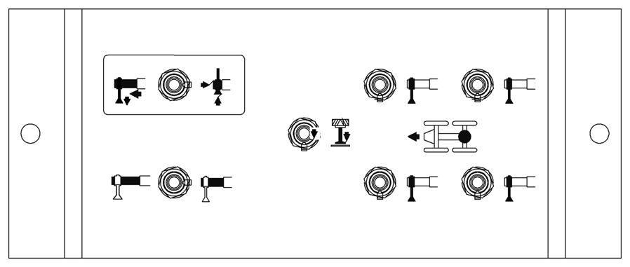
Outrigger Control Summary
There is an OUTRIGGER CONTROL panel located on each side of the crane carrier. Each panel contains switches for extending and retracting the outrigger beams and for raising and lowering the outrigger stabilizer (jack) cylinders on all sides of the crane. Each control panel also contains a control switch for raising and lowering the center front stabilizer. The following paragraphs explain these controls.
Outrigger Control Panel
There is one OUTRIGGER CONTROL PANEL (1) on each side of the unit’s frame. The panel on the right side operates the outrigger beams for that side only. The panel on the left side operates the outrigger beams for that side only. The stabilizers may be operated from the left or right side of the unit.
Outrigger Beam Selector Switch
The OUTRIGGER BEAM SELECTOR switch (2) is used to indicate desired operation of the front or rear outrigger beam for the side of the unit the control panel is on.
Extend/Retract Switch
The EXTEND/RETRACT switch (3) will operate both the outrigger beams or the stab ilizers. After positioning the desired selector switch, positioning the extend/retract switch energizes the control solenoid to allow hydraulic fluid to flow through the control solenoid valve and the individual solenoid valve and move the selected component in the desired direction. In addition, when the switch is positioned to either position, a signal is sent to the engine ECM to increase engine speed above idle for operation of the outriggers.
Center Front Stabilizer Switch
The CENTER FRONT STABILIZER switch (4) is located in the center of the outrigger control panel. It must be used in conjunction with the extend/retract switch to control the operation of the center front stabilizer. The center front stabilizer will retract automatically when any of the other four stabilizers are retracted; therefore, it must be reset if lifting is to be continued.
Stabilizer Selector Switch
The STABILIZER SELECTOR switch (5) is used to indicate which stabilizer is desired to operate.
Daytime Running Lights
Daytime running lights is a feature in which the headlight low beams will come on automatically anytime the carrier ignition switch is in the on position, engine is running, and the park brake is released regardless of the position of the headlight switch.
Superstructure Cab
NOTE: The following paragraphs describe all the available (standard and optional) controls and indicators located in the cab. Some machines may not be equipped with the optional controls shown. The numbers in () represent the index number from (Figure 3-3).
NOTE: All rocker switches contain one or two LED’s in the switch for illumination.
Engine Controls and Indicators
Engine Increment/Decrement Switch
The engine increment/decrement switch (31) located on the right side console is used to set the engine operating speed. It is a two position (+/-) momentary switch.
Pushing the top of the switch quickly increases (+) engine RPM to the maximum allowed operating speed. Pushing the bottom of the switch quickly decreases (-) engine RPM to idle speed. Pushing and holding either side of the switch will increase or decrease engine speed. Releasing the switch will hold the engine at the current speed. Pressing the foot pedal will increase engine sp eed above the “hold” speed. Releasing the foot pedal causes the engine to return to the “hold” speed.
Gauge Cluster
The gauge cluster (29) is located on the left side of the pedestal mounted console beside the LMI panel and contains a voltmeter, oil pressure gauge, water temperature gauge, and a fuel quantity gauge.
Voltmeter
The voltmeter (VOLTS) is located on the lower right of the gauge cluster. With the ignition switch in the run (between vertical and right) position and before starting the engine, the voltmeter indicates the condition of the batteries. With the engine running, the voltmeter indicates output voltage of the alternator. The voltmeter scale is from 10 to 16 volts.
Engine Oil Pressure Gauge
The engine oil pressure (OIL) gauge is located on the upper right of the gauge cluster. The gauge indicates the engine oil pressure on a scale calibrated from zero (0) to 80 psi. It receives a signal from the crane’s electronic operating system which receives the signal from the engine ECM via J1939.
Water Temperature Gauge
The engine coolant temperature (TEMP) gauge is located on the lower left of the gauge cluster. The gauge indicates the engine coolant temperature on a scale calibrated from 100 to 240° F. The gauge receives a signal from the crane’s electronic operating system which receives the signal from the engine ECM via J1939.
Fuel Quantity Gauge
The fuel quantity (FUEL) gauge is located on the upper left of the gauge cluster. The gauge indicates the quantity of fuel in the tank and has a scale calibrated from empty (E) to full (F). The fuel quantity gauge a signal from the crane’s electronic operating system which monitors a sending unit in the fuel tank.
Ignition Switch
The ignition switch (32) is located on the right side console. The switch is key operated with four positions: accessory (left position), off (vertical position), run (position between vertical and right), and start (right position). The switch is spring returned from start to run. In the off position, all electrical power in the superstructure is off except for the boom work lights, cab work lights, dome light, swing horn, and accessory outlet. In the accessory position, all electrical components are energized. Placing the switch in the start position energizes the starter motor solenoid for starting the engine. Releasing the switch will allow it to spring return to the run position. To shut down the engine, turn the switch to the off position.
Tachometer
The tachometer (27) is located on the pedestal mounted console and registers engine RPM. The tachometer is calibrated in rpm x 100 with a range of zero (0) to 35. It receives a signal from the crane’s electronic operating system which receives the signal from the engine ECM via J1939.
Hourmeter
The hourmeter (28) is located at the bottom of the tachometer and registers the total hours that the engine has run. The hourmeter receives an electrical signal from the tachometer.
Engine Stop/Module Off Line Indicator
The engine stop/module off line indicator (48) is located on the top left side of the pedestal mounted console. The top portion of the switch is the stop indicator. It illuminates red when energized by a signal from the engine ECM that signifies a serious engine problem that requires the vehicle and the engine to be stopped as soon as safely possible. In addition, a warning buzzer will also sound.
The bottom portion is the module off line indicator. This indicator will come on solid and a buzzer will sound whenever communication with one of the crane’s electronics modules is lost. The vehicle should be stopped as soon as safely possible. The crane must be restored to proper condition before operating again.
Published 12-23-2008, Control # 132-03
Engine Warning/Electrical System Diagnostic Indicator
The engine warning/electrical system diagnostic indicator (24) is located at the top left side of the pedestal mounted console. The top portion is the warning indicator. It illuminates amber when energized by a signal from the engine ECM that signals the operator of an engine problem which must be corrected.
The bottom portion of the switch is the electrical system diagnostic indicator. There are three conditions for this indicator as follows: a. On solid with buzzer sounding - There is an interruption of communication over the main canbus control line between the crane’s electronic control modules. Proper crane operating condition shall be restored as quickly as possible. b. Flashing with buzzer sounding - An undesirable condition with the crane’s joysticks has been detected. Proper crane operating condition shall be restored before performing any hydraulic function. c. Flashing without buzzer - An undesirable component or electrical system condition has occurred.
Foot Throttle Pedal
The foot throttle pedal (4) is located on the right side of the cab floor. The pedal is used to control engine RPM. The pedal modulates engine speed proportionately to the foot pressure applied.
Craning Controls and Indicators Telescope/Auxiliary Hoist/Swing Controller
The telescope or auxiliary hoist/swing controller (18) is located on the left armrest. The contro ller controls the telescope functions when the crane is not equipped with an auxiliary hoist. Pushing the controller forward actuates the control valve to telescope the boom out and pulling the controller back telescopes the boom in.
When equipped with an auxiliary hoist, the controller controls auxiliary hoist functions and telescope functions through a foot pedal (3). Pushing the controller forward actuates the control valve to let out the hoist cable and pulling the controller back reels the cable in.
When used for swing, the controller, when pushed to the right (rotates the turntable clockwise) or left (rotates the turntable counterclockwise), actuates a control valve to provide 360 degree continuous rotation in the desired direction.
Boom Lift/Main Hoist Controller
The boom lift/main hoist controller (8) is located on the right armrest. The controller, when pushed to the right (lowers the boom) or left (raises the boom), actuates the control valve to raise or lower the boom.
When used for main hoist, the controller, when pushed forward (lowers the cable) or back (raises the cable), actuates the control valve to raise or lower the main hoist cable.
Swing Horn Button
The swing horn button (20) is located on the right side of the swing controller and is used by the operator to provide a warning that the superstructure is rotating. Press in on the button to sound the swing horn.
Telescope Control Pedal
The telescope control foot pedal (3), supplied when the crane is equipped with an auxiliary hoist, is located on the right side of the cab floor. Pushing forward on the top of the pedal will extend the boom and pushing down on the bottom of the pedal will retract the boom.
Main Hoist Speed Selector Switch
The three-position main hoist speed selector switch (10) is located on the right armrest. Select the top of the switch for high speed or the bottom of the switch for low speed. Position the switch in the center position to “off” to disable main hoist functions.
Auxiliary Hoist Speed Selector Switch
The three-position auxiliary hoist speed selector switch (16) is located on the left armrest. Select the top of the switch for high speed and the bottom of the switch for low speed. Position the switch in the center to “off” to disable auxiliary hoist functions.
Hoist Rotation Indicators (Main and Auxiliary Hoist)
The hoist rotation indicators (51) are located on the top of the main and auxiliary hoist co ntrollers. Th e indicator is electronically driven by a sensor attached to the main hoist. A pulsating signal is sensed by the operator’s thumb during hoist operation.
Crane Function Power Switch
The crane function power switch (37) is located on the right side console. Push the bottom of the switch to disconnect power from the crane functions controlled by the controllers on the armrests.
Push the top of the switch to energize the pilot supply solenoid to allow functions controlled by the controllers on the armrests to be performed.
Positioning the switch to OFF prevents inadvertent operation of functions due to bumping the controllers while roading or any other operation.
Outrigger Extend/Retract Switch
NOTE: The park brake in the carrier cab must be set before the outrigger controls will operate.
NOTE: Be sure the outriggers plus the center front stabilizer are properly extended and set, and the crane is level for operation on outriggers. The center front stabilizer outrigger is a vital factor in the stability of the crane.
All four outrigger beams plus the center front stabilizer outrigger must be equally extended to the mid position vertical stripe or fully extended position before beginning operation.
The outrigger extend/retract momentary switch (44) is located on the right side console. It must be used in conjunction with the outrigger selector switches to control the operation of the stabilizer and extension cylinders.
Push the top of the switch to select the extend function or push the bottom of the switch to select the retract function. In addition, when the switch is positioned to either extend or retract position, a signal is sent to the engine ECM to increase engine speed above idle for operation of the outriggers.
Center Front Stabilizer Switch
A center front stabilizer switch (45) is located on the right side console. To extend the center front stabilizer, push the top of the outrigger extend/retract switch, then push the top of the center front stabilizer switch.
To retract the center front stabilizer, push the bottom of the outrigger extend/retract switch, then push the bottom of the center front stabilizer switch.
NOTE: The center front stabilizer will retract anytime the extend/retract switch is positioned to the retract position.
Left Front Outrigger Switch
The left front outrigger switch (11) is located on the right side console. It is a three-position switch used to extend or retract the left front stabilizer and extension cylinders. It must be used in conjunction with the outrigger extend/retract switch.
To extend the left front outrigger beam, push the top of the outrigger extend/retract switch (44) and the top of the left front outrigger switch.
To retract the left front outrigger beam, push the bottom of the outrigger extend/retract switch (44) and the top of the left front outrigger switch.
To extend the left front stabilizer, push the top of the outrigger extend/retract switch (44) and the bottom of the left front outrigger switch.
To retract the left front st abilizer, push the bottom of the outrigger extend/retract switch (44) and the bottom of the left front outrigger switch.
Right Front Outrigger Switch
The right front outrigger switch (19) is located on the right side console. It is a three-position switch used to extend or retract the right front stabilizer and extension cylinders. It must be used in conjunction with the outrigger extend/retract switch.
To extend the right front outrigger beam, push the top of the outrigger extend/retract switch (44) and the top of the right front outrigger switch.
To retract the right front outrigger beam, push the bottom of the outrigger extend/retract switch (44) and the top of the right front outrigger switch.
To extend the right front stabilizer, push the top of the outrigger extend/retract switch (44) and the bottom of the right front outrigger switch.
To retract the right front stabilizer, push the bottom of the outrigger extend/retract switch (44) and the bottom of the right front outrigger switch.
Left Rear Outrigger Switch
The left rear outrigger switch (43) is located on the right side console. It is a three-position switch used to extend or retract the left rear stabilizer and extension cylinders. It must be used in conjunction with the outrigger extend/retract switch.
To extend the left rear outrigger beam, push the top of the outrigger extend/retract switch (44) and the top of the left rear outrigger switch.
To retract the left rear outrigger beam, push the bottom of the outrigger extend/retract switch (44) and the top of the left rear outrigger switch.
To extend the left rear stabilizer, push the top of the outrigger extend/retract switch (44) and the bottom of the left rear outrigger switch.
To retract the left rear stabilizer, push the bottom of the outrigger extend/retract switch (44) and the bottom of the left rear outrigger switch.
Right Rear Outrigger Switch
The right rear outrigger switch (42) is located on the right side console. It is a three-position switch used to extend or retract the right rear stabilizer and extension cylinders. It must be used in conjunction with the outrigger extend/retract switch.