12 minute read
TMS800E OPERATOR’S MANUALSET-UP AND INSTALLATION


1. Retract the main boom completely and lower it into the horizontal position.
2. Unreeve the hoist cable from the hook block and remove it from the boom extension.
3. Fold in the deflection sheave on the 33 ft (10.1 m) section.
4. Disconnect electrical connection between the lattice extension and the main boom.
5. Attach auxiliary crane sling to bi-fold swingaway extension.
Warning
Lattice extension must be supported by an auxiliary crane before removing pins.
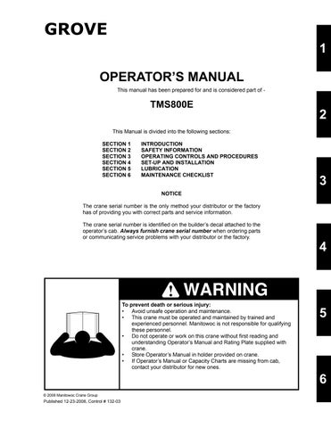
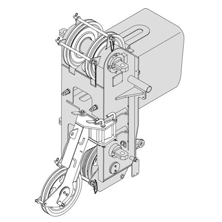
6. Remove locking pins Figure4-58 on both sides between 33 ft (10.1 m) section and main boom head and remove the bi-fold swingaway extension.
• Using an auxiliary crane with sling, lift the 16 ft (4.9 m) section with support roller on an auxiliary crane and lift it in front of the main boom head so that the bearing points (2) and (3) align on both sides.
• Insert the securing pins into the bearing points (2) and (3) on both sides.
• Secure all pins with retaining pins.
• Install the second 16 ft (4.9 m) section in front of the first 16 ft section for the 89 ft (27.1 m) boom extension in the same way.
7. Check the transport condition of the bifold swingaway extension.
INSTALLING/REMOVING 16 FT (4.9 M) SECTIONS
- In order to rig the 72 ft (22 m) boom extension, you must install the 16 ft (4.9 m) section with support roller in front of the main boom head.
- In order to rig the 89 ft (27.1 m) boom extension, you must additionally install the 16 ft (4.9 m) section without support roller in front for the 16 ft (4.9 m) section with support roller.
NOTE: An auxiliary crane must be used to install and remove the 16 ft (4.9 m) sections.
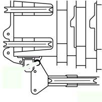
Installing the 16 ft (4.9 m) Sections
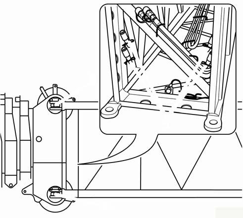
The securing pins (1) for the connection are secured with retaining pins in the holders at the foot of the 16 ft (4.9 m) sections Figure4-59.
• Install 56 ft (17.1 m) section in front of the respective 16 ft (4.9 m) section per previous instructions in this section.
Removing the 16 ft (4.9 m) Sections
• Using an auxiliary crane with sling, lift the 16 ft (4.9 m) section until the bearing points (2) and (3) are relieved.
• Release the pins and knock them out of the bearing points (2) and (3) on both sides.
• Insert the pins into the holders at the foot of the 16 ft (4.9 m) sections and secure them with retaining needles.
BOOM EXTENSION (ADDITIONAL EQUIPMENT)
Identification and Slinging Points
Identification
The boom extension consists of the 56 ft (17.1 m) bi-fold swingaway lattice extension and two boom extension
Published 12-23-2008, Control # 132-03 sections. The boom extension is designed for the crane it was delivered with. The parts which belong to the crane have the same serial number as the crane.
The following sections are identified by the serial number:
- All parts of the 56 ft (17.1 m) bi-fold swingaway lattice extension.
- Both sections of the boom extension 16 ft (4.9 m) sections)
Caution
Operate the crane only with those sections of the boom extension which have the same serial number as the crane. This prevents malfunctions and damage.
NOTE: For technical reasons a crane may only be set with one boom extension.
If you wish to use the boom extension on several Manitowoc/ Grove cranes, the parts of the boom extension must be adjusted for these cranes and labeled with all of the respective serial numbers.
Caution
Have the adjustment of the boom extension only carried out on site by Grove CraneCARE!
Serial numbers on the 16 ft (4.9 m) sections
The serial number is on a plate at the front of the 16 ft sections.
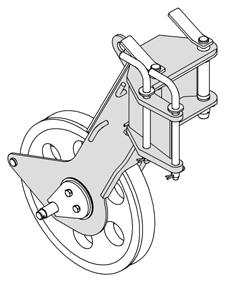
Slinging Points
Caution
This section shows the slinging points of the 16 ft (4.9 m) sections. Attach the sections only to these slinging points because they will then automat ically have the correct center of gravity. Use only lifting gear with sufficient load bearing capacity.
The 16 ft (4.9 m) sections have two slinging points (one slightly offset on each side).
NOTE: For electrical connections at the 16 ft (4.9 m) sections, refer to Electrical Connections at the Boom Extension, in this section.
Assembly Of Boom Extensions
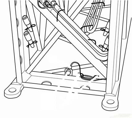
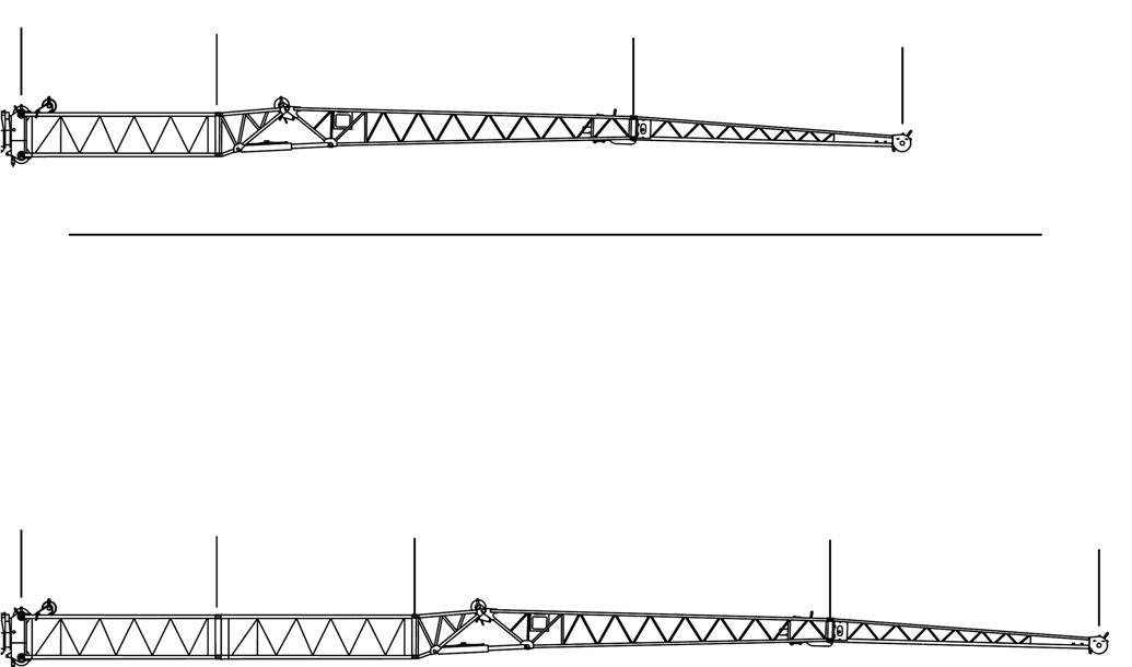
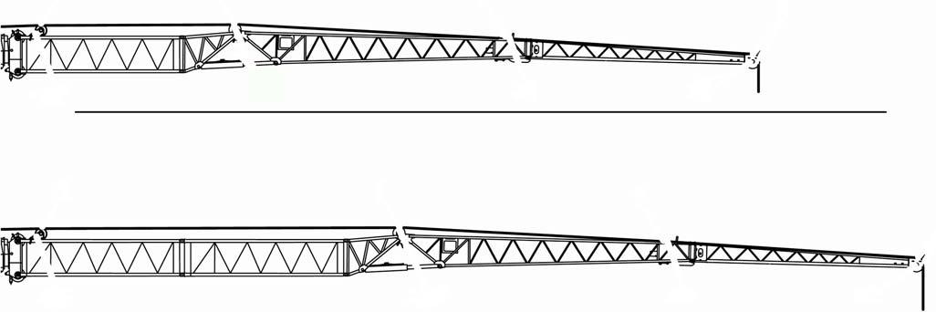
NOTE: FIGURE4-60 The lengths of 72 ft (22.0 m) and 89 ft (27.1 m) respectively equal the distance between the center of the locking pin (on the main boom head) and the front edge of the head sheave.
The designation 33 ft (10.1 m) section, 23 ft (7 m) section, and 16 ft (4.9 m) section have been adjusted to these lengths.The total length of the individual sections is greater or smaller.
Electrical Connection at the Boom Extension
The following describes the electrical connections at the 16 ft sections. Establish the electrical connection at the bi-fold swingaway lattice extension per the following procedures
Transport Condition of the Connection
For transport, bring the electrical connections always into the following condition.
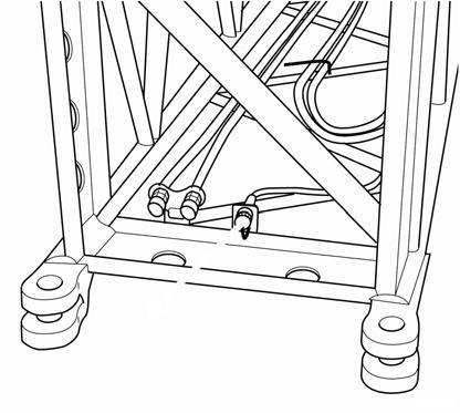
There is a cable with a plug (3) at the rear of the 16 ft sections Figure4-61.
For transport, the cable is wound around the holders (1) and the plug is inserted in the dummy socket (2).
Published 12-23-2008, Control # 132-03
There is a plug socket (1) at the front of each 16 ft (4.9 m) section Figure4-62.
For transport, the sockets are covered with protective caps.
At the 72 ft (22.0 m) Boom Extension
Establishing a Connection
• Connect the cable of the 33 ft (10.1 m) section to the socket of the second 16 ft (4.9 m) section at the front.
• Connect the cable of the 16 ft (4.9 m) section to the socket at the main boom.
Disconnecting
• Detach the electrical connection between 33 ft (10.1 m) and 16 ft (4.9 m) section.
• Detach the electrical connection between 16 ft (4.9 m) section and main boom head.
• Prepare the electrical connections at the 33 ft (10.1 m) section for transport.
At the 89 ft (27.1 m) Boom Extension
Establishing a Connection
• Connect the cable of the 33 ft (10.1 m) section to the socket of the second 16 ft (4.9 m) section at the front.
• Connect the cable of the second 16 ft (4.9 m) section to the socket of the first 16 ft (4.9 m) section at the front.
• Connect the cable of the first 16 ft (4.9 m) section to the socket at the main boom head.
Disconnecting
• Detach the electrical connection between the 33 ft (10.1 m) and front 16 ft (4.9 m) section.
• Detach the electrical connection between the two 16 ft (4.9 m) sections.
• Detach the electrical connection between the rear 16 ft (4.9 m) section and the main boom head.
• Prepare the electrical connections at the 16 ft (4.9 m) section for transport.
• Prepare the electrical connections at the 33 ft (10.1 m) section for transport.
Unfolding/Folding the Deflection Sheave on the 16 ft (4.9 m) Section
This section describes only the unfolding and folding of the deflection sheave on the 16 ft (4.9 m) section.
For work with the boom extension, you must fold out the deflection sheaves on the rear 16 ft (4.9 m) section.
Fold the deflection sheave for transport.
Folding Out Deflection Sheave
• Pull the pin (2) out of the bore (3) Figure4-63.
• Fold the deflection sheave on the strut (1) upwards until the locking positions are aligned with the bore hole (3).
• Fasten the deflection sheave for transport.
Folding In Deflection Sheave
Positioning Hoist Cable
• Remove the hoist rope holding rollers and rods (1) Figure4-65.
• Guide the hoist rope via the deflection sheaves (3) and via the head sheave (2) on the 33 ft (10.1 m) section or on the 23 ft (7 m) section. Put all hoist cable holding rollers and rod back in place and secure these with retaining pins.
• Attach the overhaul ball.
• Install the A2B weight assembly.
Removing Hoist Cable
Danger
Risk of accidents due to falling parts.
• Hold the deflection sheave by the strut (1) and remove the pin (3) from the bore (2) Figure4-64.
• Fold the deflection sheave down as far as possible.
• Insert the pin in the bore hole (3) and secure it with a retaining needle.
Positioning/Removing the Hoist Cable
Danger
Risk of accidents due to falling parts.
Always secure the hoist cable holding rollers and rods with retaining pins. This prevents elements from becoming loose, falling down and injuring people.
Always secure the hoist cable holding rollers and rods with retaining pins. This prevents elements from becoming loose, falling down and injuring people.
• Unpin the overhaul ball.
• Remove the hoist rope holding rollers and rods (1) Figure4-65.
• Take the hoist cable off the head sheave (2) and the deflection sheaves (3) and place it onto the ground on the left side.
• Put all hoist cable holding rollers and rods back in place and secure them with retaining pins.
Traveling with Manually Offsettable Boom Extension and/or Inserts Erected
33 ft (10.1 m)/56 ft (17.1 m) Extension Plus 16 ft (4.9 m) or 32 ft (10 m) Inserts
Travel is permissible under the following conditions.
1. The 33 ft (10.1 m) or 56 ft (17.1 m) boom extension shall be erected at minimum offset.
2. Jobsite travel only on firm, level surface.
3. Main boom shall be fully retracted.
4. Main boom angle: 0 degrees minimum, 40 degrees maximum.
5. Maximum travel speed: 2.5 mph (4 km/h).
6. Counterweight shall be installed.
7. The boom shall be over the front.
8. Swing lock and pin shall be engaged.
9. Hookblock must be removed from main boom nose.
10. Headache ball may be reeved over boom extension, hanging 3 feet (0.9 m) below sheave.
11. The tires shall be properly inflated.
AUXILIARY SINGLE-SHEAVE BOOM NOSE (ADDITIONAL EQUIPMENT)

Identification
The auxiliary single-sheave boom nose is designed for the crane it was delivered with.
Caution
Operate the crane only with the auxiliary single-sheave boom nose that has the identical serial number.
If you wish to use the auxiliary single-sheave boom nose on several Manitowoc/Grove cranes, it needs to be adapted to the corresponding crane and marked with all the serial numbers.
Caution
The auxiliary single-sheave boom nose should only be adjusted by Manitowoc CraneCARE at the particular location.
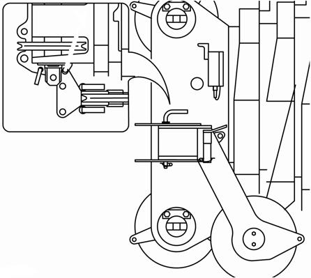
The serial number (1) is on a plate, in the front on the auxiliary single-sheave boom nose Figure4-66.
Installing/Removing Auxiliary Single-Sheave Boom Nose
Danger
Risk of accidents if boom nose should fall off! During installation and removal, always use the proper materials with sufficient load bearing capacities.
Installing Auxiliary Single-Sheave Boom Nose
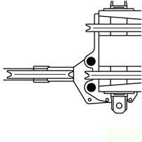
• Loosen the retaining pin (4) and remove the pins (1) from the bearing point (2) Figure4-67.
• Use an auxiliary crane to couple the holding device to the connection eyes (3) on the auxiliary boom nose and lift it to the left onto the main boom head.
• Align the auxiliary single-sheave boom nose so that the bearing point (2) lines up to the front bore holes in the holding device.
• Secure the auxiliary single-sheave boom nose to the holding device using a pin (1).
• Secure the pin (1) with a retaining pin (4).
• Depending on the application, bring the auxiliary singlesheave boom nose into transport position or working position.
Removing the Auxiliary Single-Sheave Boom Nose
• Remove the retaining pins and draw all the pins out of the bores and bearing points.
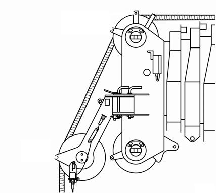
• In the transport position, the auxiliary single-sheave boom nose is positioned to the side of the main boom head and is fastened with two pins.
• Lift the auxiliary single-sheave boom nose from the head of the main boom.
• Insert the two thin pins (1) and (3) into the bearing points (2) and (4) on the auxiliary single-sheave boom nose Figure4-69.
• Insert the two pins (5) into the mounting brackets (6) in front on the auxiliary single-sheave boom nose.
• Secure all pins using retainer pins.
RIGGING THE AUXILIARY SINGLE-SHEAVE BOOM NOSE
Rigging in Transport Position
• Attach an auxiliary crane to the connection eyes of the boom nose.
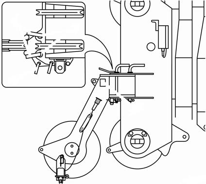
In the working position, the auxiliary single-sheave boom nose is positioned in front of the main boom head and is fastened with three pins (1) Figure4-68.
• Remove the retaining pins and draw all the pins out of the bores and bearing points.
In the transport position, the auxiliary single-sheave boom nose is positioned to the side of the main boom head and is fastened with two pins.
On the left side of the main boom head there is a holding device. In transport position, the boom nose is connected to the rear bore holes on the holding device Figure4-70.
Published 12-23-2008, Control # 132-03
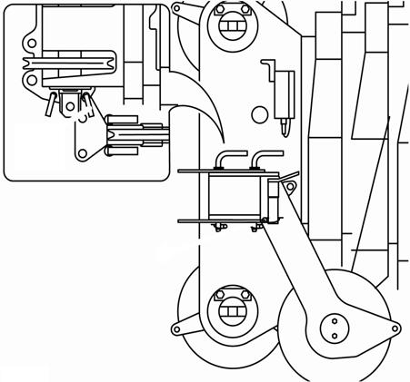
• Remove the retaining pins and take both pins (1) out of the bearing points (2) at the front of the main boom head Figure4-71.
• Insert both pins into the holders (3) and secure them with retaining pins.
• Release the retaining pin and remove the thin pin from the bearing point (4).
• Slew the auxiliary boom nose to the side of the main boom head.
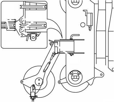
• Using the thin pin (1), fasten the auxiliary single-sheave boom nose to the bearing point (2) Figure4-72.
• Secure the pin with a retaining pin.
• The auxiliary single-sheave boom nose is now in transport position.
Rigging in Working Position
On the left side of the main boom head, there is a holding device. In working position, the auxiliary single-sheave boom nose is attached to the main boom head at both bore holes Figure4-73.
• Release the retaining pin and remove the thin pin from the bearing point Figure4-74.
• Swing the auxiliary single-sheave boom nose in front of the main boom head.
• Remove the retaining pin and take out both thick pins from the holders Figure4-75.
• Insert both pins into the pivot points at the front of the main boom head and secure them with retaining pins.
• Insert the thin pin into the bearing point and secure it with a retaining pin.
The auxiliary single-sheave boom nose is now in working position.
Attaching and Removing Hoist Cable
• When reeving, guide the hoist cable over the left hand upper sheave of the main boom.
• Insert the rope holding rod into the appropriate bore holes and secure them with the corresponding retaining pins.
• Fasten the cable end clamp on the hook tackle or the hook block.
Reverse the sequence of operations to remove the hoist cable before slewing the auxiliary boom nose into transport position.
Possible Reeving Methods on the Auxiliary Single-Sheave Boom Nose
NOTE: The hoist cable may only be simply reeved (single drop).
• maximum load bearing capacity:
• for single-reeving 16,000 lbs (7.3 t)
Lifting Limit Switch In Operation
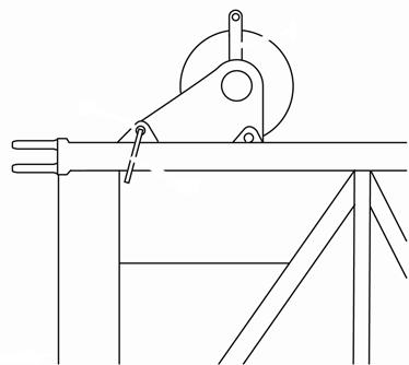
• Remove the cable holding rods from the head of the main boom and from the auxiliary single-sheave boom nose Figure4-76.
• Pull the plug of the connecting cable from the dummy socket (2) Figure4-77.
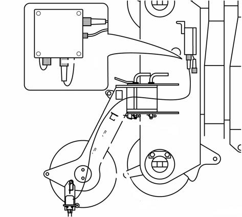
• Unwind the connecting cable from the holders (3).
• Insert the plug of the connecting cable into the socket (1) on the main boom head.
• Guide the hoist cable through the lifting limit switch weight.
Published 12-23-2008, Control # 132-03
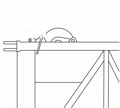
During Transport
• Insert the plug of the connecting cable into the dummy socket (2) Figure4-78
• Wind the connecting cable onto the holders (3).
• Plug the short-circuit plug into the socket (1).
Telescoping With Rigged Lattice Extension
Caution
The main boom may become overloaded!
If you telescope the main boom with a rigged lattice extension or boom extension. You must not rotate the superstructure at the same time. This prevents the main boom being subjected to additional side forces and increased vibration and becoming overloaded.
NOTE: Do not actuate the slewing gear when telescoping.
Operating With The Lattice Extension
NOTE: The information in this section also applies to operation with the boom extension. Observe the following safety instruction before working with the boom extension.
Caution
Risk of overturning when working with the boom extension!
Raising And Setting Down The Main Boom With Rigged Lattice Extension
NOTE: The information in this section also applies for raising and setting down the main boom with a rigged boom extension.
NOTE: To raise and lower the main boom with a rigged lattice extension, the main boom must be fully retracted.
For raising and lowering, the following prerequisites must be fulfilled:
- Apart from the hook block there is no load on the lattice extension.
When lifting over the swingaway and/or jib combinations, deduct the total weight of all load handling devices reeved over the main boom nose directly from the swingaway or jib capacity.
NOTE: The hoisting, lowering, swinging, lifting and telescoping movements are done in the same way as when operating with the main boom. Telescoping is permitted only at main boom angles of approximately 75° - 80°, depending on the length of the lattice extension.
Procedure if the Permissible Wind Speed is Exceeded
Strong winds can overstrain the crane. Therefore, closely observe the instructions in table.
If the maximum permissible wind speed according to the lifting capacity table is exceeded during the main boom operation, proceed per the following table (Table 4-2):