1 minute read
TMS800E OPERATOR’S MANUALSET-UP AND INSTALLATION


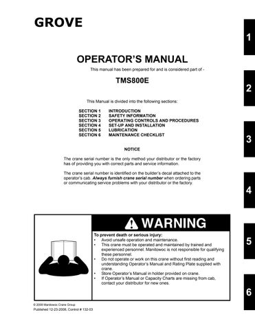
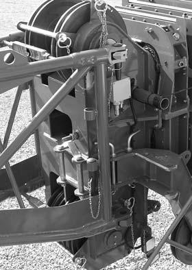
6. Remove retainer clip (1, Figure4-15) from the pin attaching the 7m (23 ft) section to the base section.
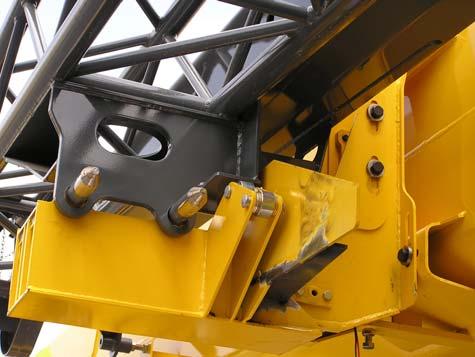
10. Use the controller to pivot the boom extension so that lugs (1, Figure 4-18) on boom extension align with the holes in the lugs (2) on the boom nose.
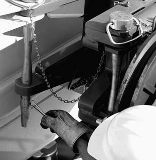
11. Remove pins (1, Figure4-19) stowed in extension and install in holes (right side of boom nose) and secure with retainer clips (2).
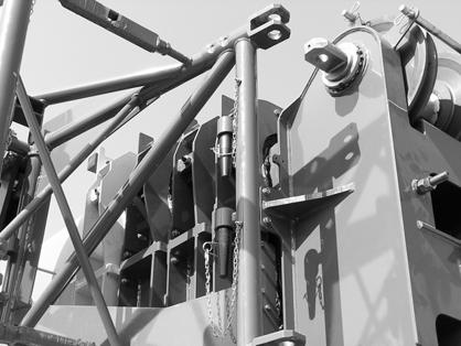
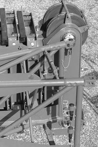
12. Remove the clip pin (1, Figure 4-20) from the stowage pin (2) at the front mount. Unpin the stowage pin (2) and store in holder (3).
Published 12-23-2008, Control # 132-03
13. Extend the boom approximately 60.9 cm (2 feet) to move extension (1, Figure 4-21) off of the ramp (2).
NOTE: Step 17 is with the 7m (23 ft) section stowed on boom.
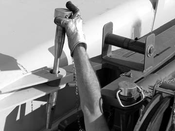
17. While maintaining control with the tag line, swing extension into position on boom nose. The 7m (23 ft) section will remain on the boom.
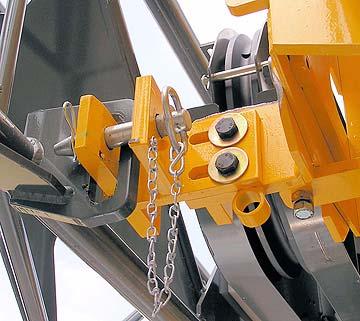
18. Remove pins from holders and install pins (1, Figure4-23) on left side of boom nose and secure with retainer clips. Lower pin (2) is shown in pin holder, remove from holder and install on boom nose.
14. Remove tag line from superstructure.
NOTE: Tag line is used to control movement of the boom extension during erecting procedure.
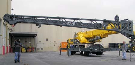
Danger
To prevent serious injury or death, do not stand on the crane deck to pull extension off ramp.
NOTE: If erecting the 7 m (23 ft) section with the 10.1 m (33 ft) section, perform steps 18 and 19. If erecting the 10.1 m (33 ft) section without the 7 m (23 ft) section, proceed to step 17.
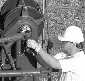
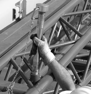
15. Using the tag line (rope), pull the extension away from the boom Figure4-22.
16. While maintaining control of the extension with the tag line, swing extension into position on boom nose Figure4-22.
Relieving the Load on Bearing Points
NOTE: The dead weight of the lattice extension can cause the bearing points on the left side to be misaligned or the pins to get weighted which makes it impossible to knock them out.
When establishing or disconnecting the connections, proceed as follows:
• Lower the lattice extension until it is on the ground with the supports (1, Figure 4-24). If necessary, override the lifting limit switch.
• Continue to lower carefully until the connecting points (1, Figure 4-25) align or until the load has been removed from the pins.