5 minute read
TMS800E OPERATOR’S MANUALOPERATING CONTROLS AND PROCEDURES


crane parking brakes are applied. It is illuminated by a pressure switch on the parking brake valve.
The bottom of the indicator illuminates red to warn the operator that the swing brake release pressure is not enough to hold the swing brake disengaged during trailing boom operation. In addition to illuminating the indicator, a warning buzzer will sound.
Cross-Axle Differential Locked Indicator (Optional)
The cross-axle differential locked indicator (26) is located at the left center side of the front console. The amber indicator illuminates to show that the cross axle differential is locked.
Caution
Do not operate the cross axle differential lock or the interaxle differential lock on dry roads.
Cross-Axle Differential Lock Switch (Optional)
The cross-axle differential lock switch (17) is located on the left center side of the front console and is used to lock the right and left wheels in a tandem set. The cross-axle differential lock increases tracti on on slippery roads. It is a two position lock/unlock switch. Press top of switch for the lock position or bottom of switch for the unlock position.
Caution
Do not operate cross-axle differential lock while crane wheels are spinning or at speeds over approximately 16 km/h (10 mph). Release the throttle when locking or unlocking.
Inter-Axle Differential Lock Switch
The inter-axle differential lock switch (15) is located on the left center side of the front console. In the lock (press top of switch) position, both rear axles are locked together and turning at the same speed. In the unlocked (press bottom of switch) position, the axles operate independently of each other.
Inter-Axle DIfferential Lock Indicator
The inter-axle differential lock indicator (32) is located on the left center side of the front console. The amber indicator illuminates when the inter-axle differential lock is engaged.
Brake Pedal
The brake pedal (37) is located on the cab floor, to the left of the foot throttle, and is used to apply the service brakes.
Clutch Pedal
The clutch pedal (59) is located on the cab floor, to the left of the brake pedal, and is used to apply the clutch. Refer to OPERATING PROCEDURES in this section for complete clutch and transmission operating instructions.
Transmission Shift Lever
The transmission shift lever (40) is located on the right side of the cab. It is used to select the transmission gears. Refer to OPERATING PROCEDURES in this section for complete clutch and transmission operating instructions.
Trailing Boom Trailer Emergency Brake Control (Optional)
The trailing boom (trailer emergency) brake control (11) is a push-pull type air valve located on the right side of the front console. The control is used to set and release the brakes on the trailing boom trailer.
Swing Brake Engaged Indicator (Optional)
swing brake engaged indicator (29) is located on the top left side of the front console. The indicator illuminates when there is sufficient pressure to hold the swing brake disengaged during trailing boom operation. In addition to illuminating the indicator, a warning buzzer will sound.
Suspension Inflation Control Switch
The suspension inflation control switch (34) is located on the right side console. When positioned to the right to inflate, the suspension air bags are inflated. When positioned to the left to deflate, the suspension air bags are deflated.
NOTE: The suspension air bags should be inflated at all times except when on outriggers or in a pick and carry mode.
Suspension Deflated Indicator
The SUSPENSION DEFLATED indicator (33) is located on the right side console. The amber indicator illuminates when the air is removed from the suspension air bags. It is controlled by four pressure switches connected in series.
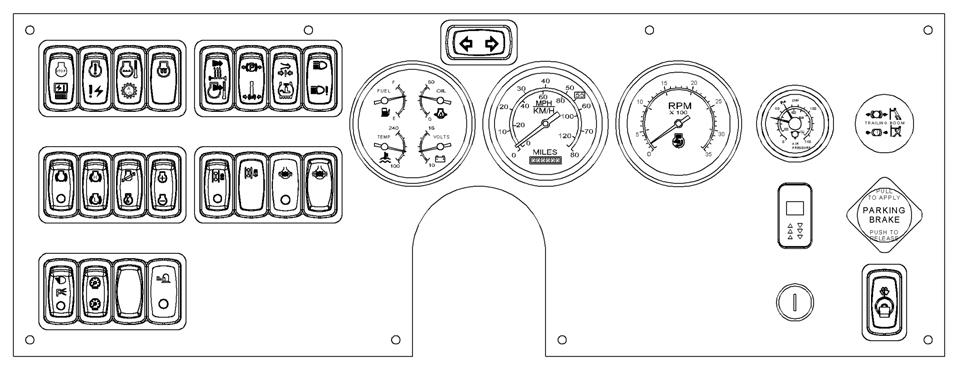
ItemDescription
1Dual Air Pressure Gauge
2Tachometer
3Left Turn Signal Indicator
4Speedometer
5Gauge Cluster (fuel, temperature, oil, volts)
6Right Turn Signal Indicator
7Heater On/Off Switch
8Heater/Air Conditioner Fan Switch
912 Volt Accessory Outlet
10Air Conditioner Switch (Optional)
11 Trailing Boom Trailer Emergency Brake Control (Optional)
12Parking Brake Control
13Windshield Wiper/Washer Switch
14Ignition Switch
15Inter-Axle Differential Lock Switch
16Odometer
17Cross-Axle Differential Lock Switch (Optional)
18Tire Inflation Switch
19Beacon Light Switch (Optional)
ItemDescription
20Engine Brake High-Low Switch
21Headlights Switch
22Engine Brake On/Off Switch
23Engine Stop/Module Off Line Indicator
24Engine Warning/Electrical Diagnostic Indicator
25Engine Coolant Temperature Indicator
26
Cross-Axle Differential Locked Indicator (Optional)
27Low Air Pressure/Tire Inflation On Indicator
28High Beam/Lamp Malfunction Indicator
29
Park Brake Engaged/Swing Brake Engaged Indicator (swing brake may be optional)
30Not Applicable
31Dimmer Switch
32Inter-Axle Differential Lock Indicator
33Suspension Deflated Indicator
34Suspension Inflation Control Switch
35Engine Idle Switch
36Not Applicable
ItemDescription
37Brake Pedal
38Throttle Pedal
39Carrier Electrical Diagnostic Connector
40Transmission Shift Lever
41Ash Tray
42Beacon Light (Optional)
43Fire Extinguisher
44Cab Dome Light (Not Shown)
45Steering Wheel
46Horn Button
47 Headlight Dimmer/Turn Signal Lever/Cruise Control
48Seat
49Sun Visor
50Cab Circulating Fan
51Windshield Defroster Air Outlet
52Heater Control Switch
53Cab Marker Lights
54Fuse and Relay Panel (Not Shown)
55Hazard Light Switch
56Steering Column Tilt/Telescope Lever
57Not Applicable
58Not Applicable
59Not Applicable
60Jib Stowage Controller
Caution
Do not operate inter-axle differential lock switch while crane wheels are spinning or at speeds over approximately 16 km/h (10 mph). Release the throttle when locking or unlocking.
Craning Controls and Indicators
Park Brake Engaged/Swing Brake Engaged Indicator
The park brake engaged indicator (29) is located at the top of the front console. The top of the indicator illuminates red when the crane parking brakes are applied. Illumination is determined by a pressure switch on the parking brake valve. The park brake must be set before the outrigger controls will operate.
The swing brake engaged indicator (bottom of the indicator) illuminates red to warn the operator that the swing brake release pressure is not enough to hold the swing brake disengaged during trailing boom operation. In addition, illuminating the indicator, a warning buzzer will sound. (Optional)
Accessory Controls and Indicators
High Beam/Lamp Malfunction Indicator
The headlight high beam/lamp malfunction indicator (28) is located at the top left of the center front console. The indicator is a blue light that illuminates when the headlights are on high beam or amber when there is a lamp malfunction.
Heater On/Off Switch
The heater on/off switch (7) is located on the right side console. Press the right side of the switch to ON for heat. Press the left side of the switch to turn the heater off.
Heater Control Switch
The heater control switch (52) is located on the right side console. Push the switch to the right to (OPEN) the valve for heat. Push the switch to the left to (CLOSE) the valve.
Heater /Air Conditioner Fan Switch
The heater/air conditioner fan switch (8) is located on the right side console. The switch controls the speed which in turn regulates the volume of heated air output of the heater and air conditioner fan by positioning switch to: low (switch positioned to left), medium (switch centered), and high (switch positioned to right).
NOTE: Either air condition or heater switch must be positioned to “on” before the fan will become operational.
Air Conditioner Switch (Optional)
The air conditioning switch (10) is located on the right side console. The switch controls the operation of the optional air conditioning system in conjunction with the fan switch. Press the switch to the right to turn air conditioner on. Press the switch to the left to turn the air conditioner off.
Windshield Wiper/Washer Switch
The windshield wiper/washer toggle switch (13) is located on the lower right side of the front console. The switch is used for removing moisture from the windshield.The switch has an off and high position with six intermittent positions between high and off. Pushing the switch up from the off position energizes the wiper motor. Continue to push switch up for each intermittent position and the high position. Push the switch down to off to stop the motor and return the wiper blade to the parked position.