4 minute read
TMS800E OPERATOR’S MANUALOPERATING CONTROLS AND PROCEDURES


3. Apply parking brakes and if necessary, chock the wheels.
4. Position all controls to neutral or off.
5. Shut down the engine using the proper procedures as specified by this Handbook and the engine manual.
6. Perform any other specified procedures required at the end of the workday, i.e., drain water from the fuel filterwater separator, refueling, etc.
7. Close all windows.
8. Remove the keys from the crane.
9. Lock the crane. Install vandal guards, if used.
Danger
Step 10 does not take the place of the prestarting checks which must be performed just prior to using the crane at the next working day.
10. Make a thorough walk around inspection to ensure that all cylinders that can be retracted are retracted. The only exceptions are those cylinders which cannot be fully retracted, i.e., steer cylinders. Also, look for anything that could hinder or prevent starting the next day’s work.
Published 12-23-2008, Control # 132-03
Section 4
Section 4
SET-UP AND INSTALLATION
General
This section provides procedures for installing the hoist cable on the hoist drum, cable reeving, and erecting and stowing the boom extension.
Installing Cable On The Hoist
Caution
If cable is wound from the storage drum, the reel should be rotated in the same direction as the hoist.
NOTE: The cable should preferably be straightened before installation on the hoist drum.
Install cable on the hoist drum in accordance with the following procedure.
1. Position the cable over the boom nose sheave and route to the hoist drum.
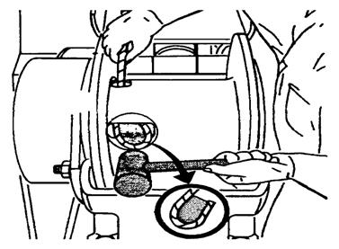
2. Position the hoist drum with the cable anchor slot on top.
3. Insert the cable through the slot and position around the anchor wedge Figure 4-1.
NOTE: The end of the cable should be even with the bottom of the anchor wedge.
4. Position the anchor wedge in the drum slot; pull firmly on the free end of the cable to secure the wedge.
NOTE: If the wedge does not seat securely in the slot, carefully tap the top of the wedge with a mallet.
5. Slowly rotate the drum, ensuring the first layer of cable is evenly wound onto the drum.
6. Install the remainder of the cable, as applicable.
Cable Reeving
NOTE: There are two types of cable (wire rope) available on this crane; 6 x 36 WS and 35 x 7 (non-rotating). Within the limits of the load and range charts and permissible line pull, multi-part lines allow the operator to raise a greater load than can be raised with a single part line. Various cable reeving (part line) is possible with the boom nose and hook block Figure 4-6 and Figure 4-7. This reeving should be accomplished by a qualified rigger using standard rigging procedures.
Caution
Do not reeve Auxiliary Hoist rope through the rope grab. Do reeve the Main Hoist rope through the rope grab. If both Main & Auxiliary Hoists are being reeved, neither one may be reeved trough the rope grab. Keep it in the down position. Figure 4-2
NOTE: Also use the rope grab when using the Main Hoist with lattice extensions to quick reeve the hook block without removing the wedge socket on the end of the cable Figure 4-3.
Published 12-23-2008, Control # 132-03
Caution
If the socket is not positioned with the flat face away from the boom sections, structural damage will occur.
When anchoring the socket to the boom, ensure the flat face of the socket is in position, as shown, away from the boom sections Figure 4-4.
DEAD-END RIGGING/WEDGE SOCKETS
Wedge socket assemblies are popular rigging accessories and have been successfully used for decades to terminate wire ropes on mobile cranes. A wedge socket assembly is easily installed and dismantled but it must be installed and used correctly. It is essential to use only a wedge and socket of the correct size for the rope fitted. Failure to do so may result in the rope pulling through the fitting.
Since state and local laws may vary, alternate attachment methods may be necessary depending upon work conditions. If alternate methods are selected, the user is responsible and should proceed in compliance with the regulations in force. If there are any questions, contact your local Grove Distributor or Manitowoc CraneCARE.
Do not mix components from different manufacturers. The selection, installation and use of a wedge socket assembly must be in accordance with the requirements of the wedge socket manufacturer and the wire rope manufacturer upon whose wire rope the wedge socket assembly will be used.
Manitowoc/Grove Crane specifies the size, type, class and line pulls for wire rope, predominately rotation resistant wire rope, and rigging accessories such as overhaul balls and hook blocks for use with each new crane that it manufactures. Other wire ropes and rigging accessories are available from various vendors. Different wire rope manufacturers have differing requirements for the construction, handling, cutting, seizing, installation, termination, inspection and replacement of the wire ropes they produce. Their advice should be sought for each specific type of wire rope a crane user intends to install on a mobile crane.
When assembly is complete, raise the boom to a working position with a load suspended to firmly seat the wedge and rope into the socket before the crane is used operationally.
Installing Wedge and Socket
1. Inspect the wedge and socket. Remove any rough edges and burrs.
2. The end of the wire rope should be seized using soft, or annealed wire or strand. If the end of the rope is welded, the welded end should be cut off. This will allow the distortion of the rope strands, caused by the bend around the wedge, to adjust themselves at the end of the line.
3. Make sure the live-loaded side Figure 4-5 of the rope is directly in line with the ears of the socket and the direction of pull to which the rope will be subjected. If the rope is loaded into the socket incorrectly, under a load the rope will bend as it leaves the socket, and the edge of the socket will wear into the rope causing damage to the rope and eventual failure.