3 minute read
TMS800E OPERATOR’S MANUALOPERATING CONTROLS AND PROCEDURES


The load chart also gives weight reductions for Manitowoc/ Grove load handling devices such as hookblocks, overhaul balls, boom extension sections, etc, which must be considered as part of the load. The weight of any other load handling devices such as chains, slings, or spreader bars must also be added to the weight of the load.
Terms To Know
NOTE: The information in the following paragraph is an example of how to compute a lift. The numbers used in the example may not coincide with the load chart in the crane cab.
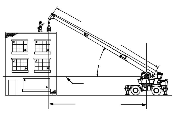
Problem: A concrete beam weighing 2268 kg (5000 lbs) needs to be lifted to a height of 9.1 m (30 ft) at a radius of 15.2 m (50 ft) (maximum). The range diagram indicates the boom must be extended to 18.9 m (62 ft) in order to reach a height of 9.1 m (30 ft) at a radius of 15.2 m (50 ft).
First we need to check the crane for load handling devices. In our example, the crane is equipped with a auxiliary boom nose (rooster sheave) and a five ton overhaul ball. The rooster sheave is 50 kg (110 lbs), and the overhaul ball is 78 kg (172lbs) for a total of 128 kg (282 lbs). The lift requires slings and spreader bars weighing 159 kg (350 lbs) which makes the total weight for the load handling devices 286 kg (632lbs).
A check of the load chart for a 15.2 m (50 ft) radius and 19.5m (64ft) of boom length shows a capacity of 3601 kg (7940 lbs) on outriggers over-front and 4970 lbs on outriggers 360 degrees. We subtract the load handling weight of 632 lbs from the load capacity of 3601 kg (7940 lbs) and 2254 kg (4970 lbs). The result is a weight capacity of 3315 kg (7308 lbs) over-the-front and 1968 kg (4338 lbs) for 360 degrees. We are constricted in making the lift over-front only and the boom angle will be about 29 degrees.
Published 12-23-2008, Control # 132-03
Crane Functions
Danger
Death or serious injury could result from improper crane setup on outriggers.
WARNING
The outriggers and the center front stabilizer must be properly extended and set and the crane level before any other operation of the crane on outriggers is attempted.
WARNING
The center front stabilizer will retract when any main outrigger stabilizer is retracted. Reset center front stabilizer if any main outrigger stabilizer is retracted or extended after initial set-up.
Setting The Outriggers
NOTE: The park brake must be set and the Hydraulic Boost switch must be in the LOW position before the outriggers will operate.
NOTE: The air suspension system must be deflated when on outriggers.
The outrigger control switches are located on the outrigger control box located in a pocket at the front of the superstructure cab. In addition, the outriggers may be operated from optional control boxes mounted on both sides of the carrier just forward of the front outriggers. When using the optional control boxes, the engine speed is increased due to a signal to the engine ECM when the EXTEND/ RETRACT switch is placed in either position.
Caution
Depress outrigger selector switch before the outrigger extension/retraction switch. Failure to do so may cause a hydraulic lock against the individual solenoid valves, and keep them from opening.
1. If outrigger floats are not already installed, remove them from float stowage locations on left, right, and rear of carrier frame. Secure the floats to the rods of the outrigger jack cylinders (aka outrigger stabilizer cylinders) using the levers on each float.
2. Depress the appropriate Outrigger Selector switch to EXTENSION and then position the Outrigger Extension/ Retraction switch to EXTEND. The outrigger beam should begin to extend. Refer to Engaging the Mid Extend Lock Pin if the crane is to be operated at the midextend position.
Danger
All four outrigger beams must be equally extended to the mid position vertical stripe or fully extended position before beginning operation.
NOTE: More than one outrigger may be extended at one time. However, each Outrigger Selector switch should be depressed individually and the outrigger extension/retraction switch momentarily positioned to EXTEND to ensure that each outrigger is fully extended.
3. After all four outrigger beams have been extended, depress the appropriate Outrigger Selector switch to STABILIZER and position the Outrigger Extension/ Retraction switch to EXTEND.
4. Extend each stabilizer, until the floats touch the ground.
NOTE: More than one stabilizer may be extended at one time.
5. After all floats are on the ground, extend the front stabilizers about 8 to 10 cm (3 to 4 inches) and then extend the back stabilizers the same distance. Repeat until all tires are off the ground.
Danger
All four outrigger beam lock pins must be engaged before operating from the mid-extend position.
Danger
Operator must select proper load chart and LMI program for the outrigger position selected.
6. Repeat step 5 until all wheels are clear of the ground and the crane is level as indicated by the sight level bubble located on the right side of the cab. If it is suspected that the bubble level indicator is out of adjustment, verify and adjust the bubble level as follows: a. Locate the crane on a firm level surface.