TMS800E OPERATOR’S MANUAL b.
OPERATING CONTROLS AND PROCEDURES
Extend and set the outriggers. Level the crane, as indicated by the bubble level indicator, with the outriggers.
c.
Place a miracle pointer, carpenter level, or similar type device on a machined surface such as the turntable bearing or bearing mounting surfaces.
d.
Level the crane with the outriggers as indicated on the device used in step (c).
e.
Adjust the bubble level indicator with the mounting screws to show level.
Stowing The Outriggers 1.
Position the rear Outrigger Selector switches to STABILIZER and position the Outrigger Extension/ Retraction switch to RETRACT until the rear stabilizers have retracted several inches.
2.
Position the front outrigger selector switches to STABILIZER and position the Outrigger Extension/ Retraction switch to RETRACT until the front stabilizers have retracted several inches.
3.
Repeat steps 1 and 2 until the crane is resting on all four wheels and the stabilizer floats are several inches off the ground.
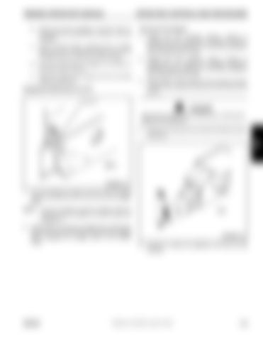
Engaging the Mid Extend Lock Pin Locking Pin
DANGER Keep feet and hands clear of floats when unlocking the floats from the stabilizers. 4.
Release the locking levers and allow the floats to drop to the ground.
3 Lug
4907-1
FIGURE 3-5 1.
Turn the locking pin (Figure 3-5) 90° from its stowed position and allow the pin to rest on top of the outrigger beam.
NOTE:
2.
It may be necessary to jog the outrigger extension/ retraction switch slightly to ensure proper pin engagement.
Slowly extend or retract the outrigger beam, allowing the locking pin to drop into the hole in the top of the outrigger beam, engaging the outrigger beam at the desired length.
GROVE
4741
FIGURE 3-6 5.
Continue to retract the stabilizers until they are fully retracted.
Published 12-23-2008, Control # 132-03
3-25


