TMS800E OPERATOR’S MANUAL
OPERATING CONTROLS AND PROCEDURES
The load chart also gives weight reductions for Manitowoc/ Grove load handling devices such as hookblocks, overhaul balls, boom extension sections, etc, which must be considered as part of the load. The weight of any other load
handling devices such as chains, slings, or spreader bars must also be added to the weight of the load.
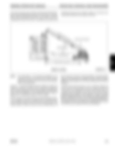
MA IN
BO
OM
LE NG
TH
AXIS OF ROTATION
BOOM ANGLE
HORIZONTAL
OPERATING RADIUS
TERMS TO KNOW
NOTE:
4605
3 FIGURE 3-4
The information in the following paragraph is an example of how to compute a lift. The numbers used in the example may not coincide with the load chart in the crane cab.
kg (172 lbs) for a total of 128 kg (282 lbs). The lift requires slings and spreader bars weighing 159 kg (350 lbs) which makes the total weight for the load handling devices 286 kg (632 lbs).
Problem: A concrete beam weighing 2268 kg (5000 lbs) needs to be lifted to a height of 9.1 m (30 ft) at a radius of 15.2 m (50 ft) (maximum). The range diagram indicates the boom must be extended to 18.9 m (62 ft) in order to reach a height of 9.1 m (30 ft) at a radius of 15.2 m (50 ft).
A check of the load chart for a 15.2 m (50 ft) radius and 19.5 m (64 ft) of boom length shows a capacity of 3601 kg (7940 lbs) on outriggers over-front and 4970 lbs on outriggers 360 degrees. We subtract the load handling weight of 632 lbs from the load capacity of 3601 kg (7940 lbs) and 2254 kg (4970 lbs). The result is a weight capacity of 3315 kg (7308 lbs) over-the-front and 1968 kg (4338 lbs) for 360 degrees. We are constricted in making the lift over-front only and the boom angle will be about 29 degrees.
First we need to check the crane for load handling devices. In our example, the crane is equipped with a auxiliary boom nose (rooster sheave) and a five ton overhaul ball. The rooster sheave is 50 kg (110 lbs), and the overhaul ball is 78
GROVE
Published 12-23-2008, Control # 132-03
3-23


