CYLINDER HEAD AND VALVES The cylinder head assembly consists of the rocker arm mechanism, valves, springs, and valve guides.
5. Disconnect the water temperature gauge from the cylinder head. Remove the radiator upper hose.
The procedures below cover the removal, disassem· bly, cleaning, inspection, repair and assembly of the cylinder head and valves.
6. Disconnect the adjusting link from the power
steering pump. Remove the bolts that attach the pump to the cylinder head and the water outlet elbow.
A. Cylinder Head Removal
7. Remove the rocker arm cover and gasket.
1. Remove the hood. Drain the coolant from the radiator and cylinder block.
8. Loosen the rocker arm support attaching bolts evenly and alternately until all tension has been relieved then :remove the bolts and washers.
2. Remove the fuel tank and fuel tank support brackets.
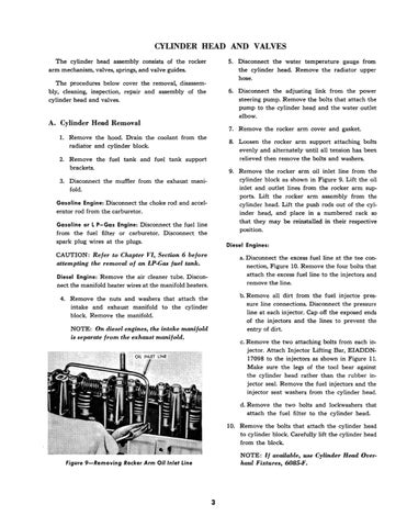
9. Remove the rocker arm oil inlet line from the cylinder block as shown in Figure 9. Lift the oil inlet and outlet lines from the rocker arm sup-ports. Lift the rocker arm assembly from the cylinder head. Lift the push rods out of the cylinder head, and place in a numbered rack so that they may be reinstalled. in their respective position.
3. Disconnect the muffler from the exhaust manifold. Gasoline Engine: Disconnect the choke rod and accelerator rod from the carburetor. Gasoline or L P-Gas Engine: Disconnect the fuel line from the fuel filter or carburetor. Disconnect the spark plug wires at the plugs.
Diesel Engines:
CAUTION: ReJer 10 Chapter n, Section 6 beJore attempting the removal oj an LP·Gas Juel tank.
a. Disconnect the excess fuel line at the tee connection, Figure 10. Remove the four bolts that attach the excess fuel line to the injectors and remove the line.
Diesel Engine: Remove the air deaner tube. Disconnect the manifold heater wires at the manifold heaters.
b. Remove all dirt from the fuel injector pressure line connections. Disconnect the pressure line at each injector. Cap off the exposed ends of the injectors and the lines to prevent the entry of dirt.
4. Remove the nuts and washers that attach the intake and exhaust manifold to the cylinder block. Remove the manifold.
NOTE: On diesel engines, the intake maniJold is separate from the exhaust manifold.
c. Remove the two attaching bolts from each injector. Attach Injector Lifting Bar, EIADDN. 17098 to the injectors as shown in Figure 11. Make sure the legs of the tool bear against the cylinder head rather than the rubber injector seal. Remove the fuel injectors and the injector seat washers f:rom the cylinder head. d. Remove the two bolts and Iockwashers that attach the fuel filter to the cylinder head.
10. Remove the bolts that attach the cylinder head to cylinder block. Ca:refully lift the cylinder head from the 'block. NOTE: If available, use Cylinder Head Over.
haul Fixtures, 6085-P.
Figure 9-Removing Rocker Arm Oil Inlet Line
3


