7 minute read
DISTRIBUTOR
cracked or having broken or damaged terminals.
Replace the coil if any of these conditions are evident. 2. Perform a coil secondary, continuity and capacity test following the instructions of the test set manufacturer. Replace the coil if not up to specifications.
C. InstaUation
L Secure the coil in the mounting bracket. 2. Hold the coil in place on the cylinder block with the terminals facing upward and secure with the two cap screws and lock washers.
3. Connect the distributor primary wire to the "DIST" terminal and the other primary wire to the "BAT" terminal with nuts and lockwashers.
NOTE: Be careful not to overtighten the pri. mary terminal nuts and break the studs.
4. Push the secondary wire (high tension) into the coil socket as far as possible then slip the rubber sea! into place.
The distributor is mounted on the right side of the engine and is driven by a gear on the camshaft. One of the distributor functions is to interrupt the current flow through the primary winding of the ignition coil, thus causing the coil to produce voltage high enough to jump the gap at the spark plugs at the desired instant during the compression stroke. As engine speed increases, the spark must occur earlier at the spark plugs. This is accomplished by an automatic spark advance that is controlled by centrifugal weights in the distributor. This is necessary to allow the fuel air mixture sufficient time to ignite and burn. The centrifugal weights, advance the breaker cam to give a predetermined variation in spark advance for different engine speeds. An accurate measurement of spark timing at any given engine rpm can only be determined on the engine by use of a timing light.
A. Removal
1. Disconnect the primary wire at the distributor. 2. Unsnap the two distributor cap bale clamps and lift the distributor cap off the distributor.
S. Scribe a mark on the dust cap opposite the rotor contact. Note the position of the primary terminal on the distributor so that it may be located in the same approximate position when installing the distributor. 4. Remove the two screws and distributor damps then lift the distributor out of the cylinder block.
NOTE: Do not crllnh the engine after tile distributor has l)een removed.
B. Disassembly
1. Place the distributor in Holding Block 12132·c'
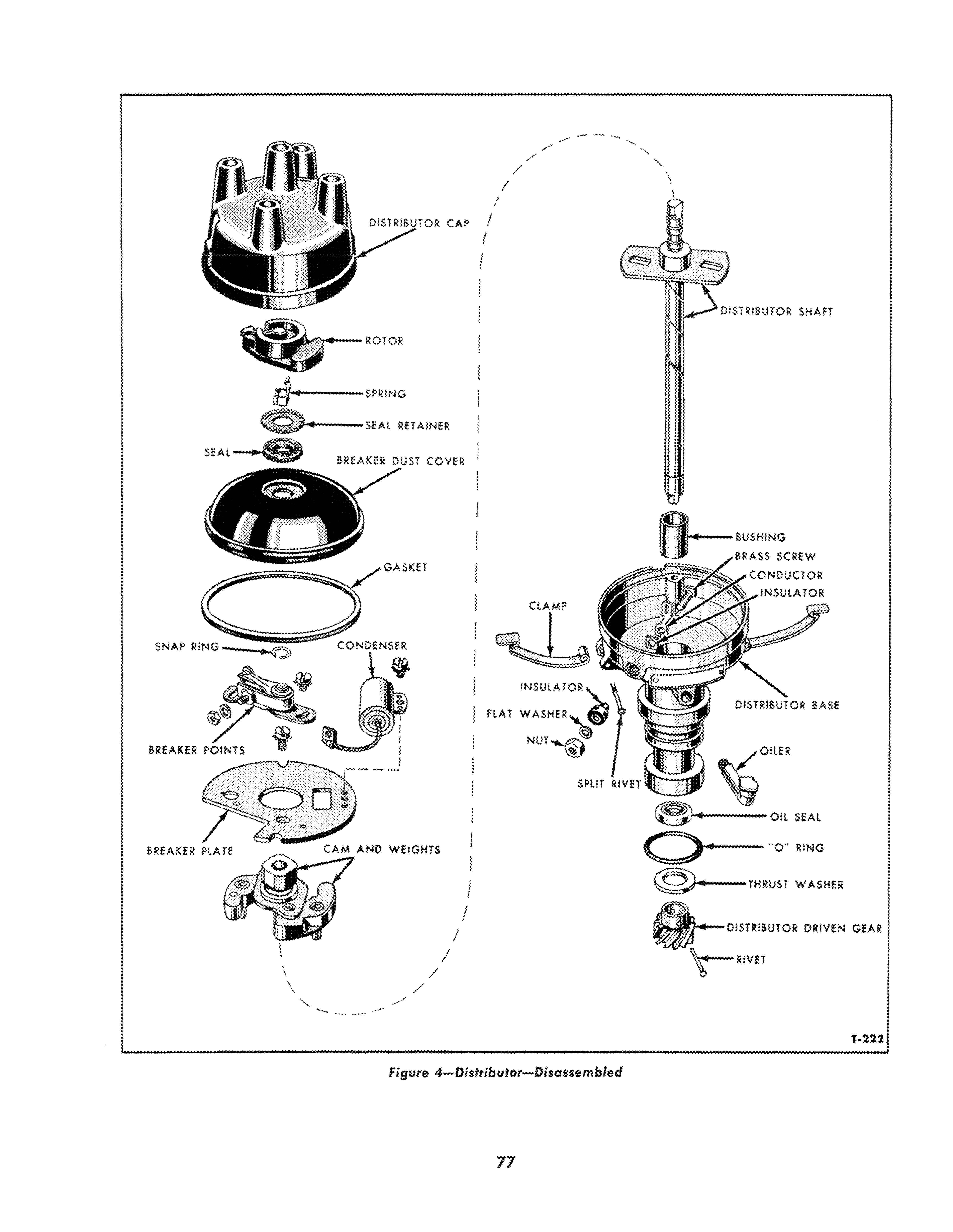
Remove the rotor and distributor shaft spring,
Figure 4, from the distributor shaft. 2. Lift the breaker dust cover, retainer, seal and gasket from the distributor as an assembly.
3. Remove the nut and lockwasher that connects the condenser lead and primary conductor to the breaker points.
4. Remove the screws that attach the breaker points and condenser to the breaker plate. S. Remove the two screws that attach the breaker plate to the distributor base. Lift the plate from the base.
6. Remove the nut, lockwBsher, insulator bushing, insulator, conductor, and brass screw from the distributor base.
7. Remove the snap ring that secures the cam and weights to the distributor shaft. Lift the cam and weights from the shaft.
8. File the upset end of the rivet that secures the distributor gear to the shaft until it is flush with the gear. Remove the rivet with a punch.
9. Remove the gear from the shaft with Remover 12390-C-3, as shown in Figure 5.
10. Carefully pry the oil seal out of the lower end of the distributor base.
11. With the distributor base in the inverted posi. tion, drive the bushing out of the base with
Distributor Shaft Bushing Remover 12132-B-l, as shown in Figure 6.
NOTE: Do not remove tlU! bushing if not necessary to replace it. See paragraph C. 2.
C. Cleaning and Inspection
1. Soak all parts of the distributor assembly (except the condenser, breaker point assembly, and
e. SPRING OR CAP I
I I I I
j I
I
RETAINER DISTRIBUTOR SHAFT
c::i GA
ClAMP
SNAP RING;:; CONDENSER fl#

INSULATOR
8REAKER "LATE flAT
I
CAM AND WEIGHTS
I I I I I I
I
I
NUT
SPlIT River 'l:f e.. . 0----OIL "0" SEAL RING
@-.-THRUST WASHER
DISTRIBUTOR DRIVEN GEAR
Figure 4-Distribulor-Disossembled
6. Replace the primary conductor and the insulator if broken or damaged.
7. Check the distributor base for cracks or other damage. Replace all defective parts.
D. Assemhly
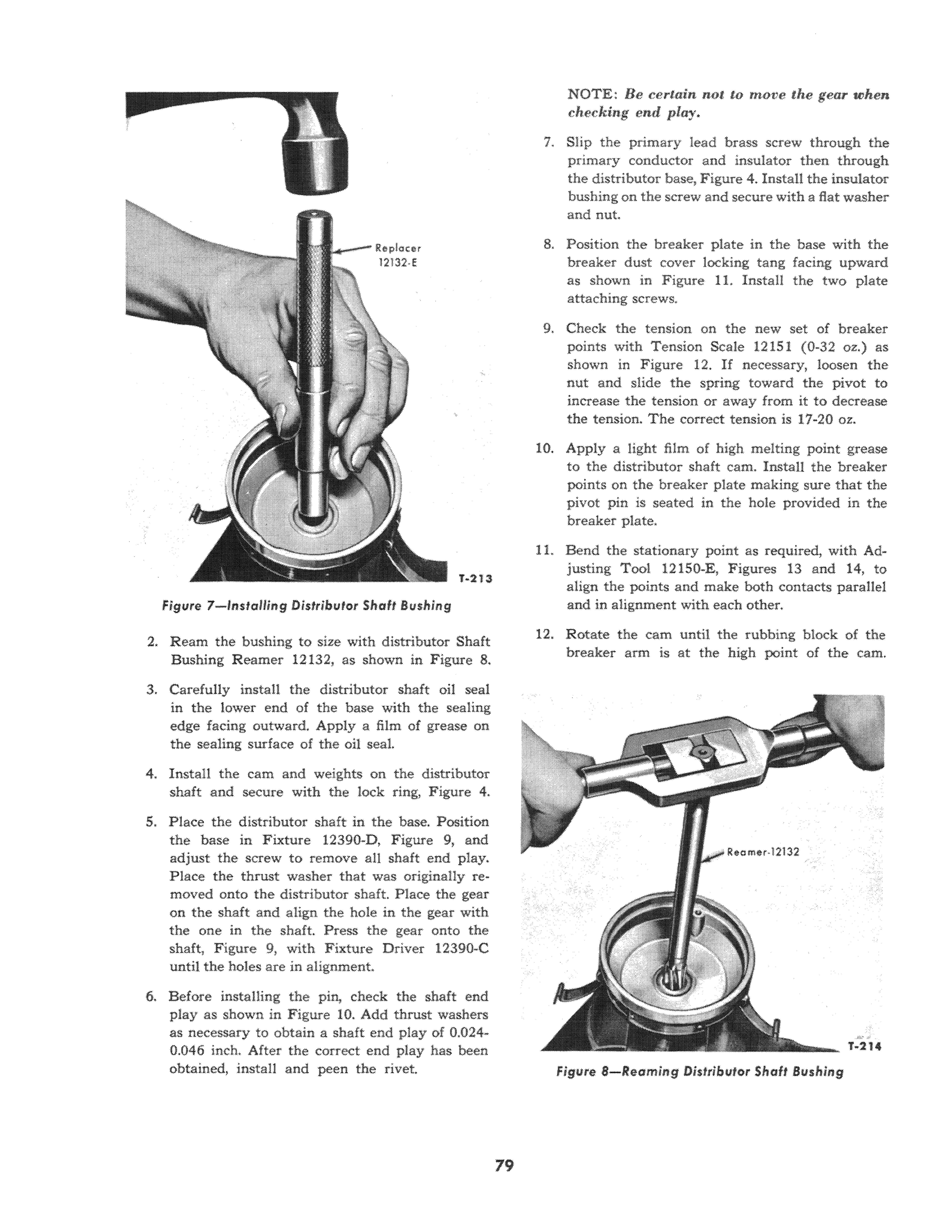
1. Place the distributor base in Holding Block 12132-C. Drive a new distributor shaft bushing into the housing with Distributor Shaft Bushing
Replacer 12132-E, as shown in Figure 7, jf it was removed.
figure 5- Removing Distributor Gear
insulator) in a mild cleaning solvent or mineral spirits. DO NOT USE A HARSH CLEANING SOLUTION. Wipe all parts that can not be immersed in a solvent with a dry, clean cloth. After foreign deposits have been loosened by soaking, scrub the parts with a soft bristle brush. DO NOT USE A WIRE BRUSH, FILE OR OTHER ABRASIVE OBJECT. Dry the parts with compressed air.

2. Examine the bushing surfaces of the distributor shaft and examine the bushing for wear. The minimum allowable shaft diameter at the bushing surface is 0.4665". The maximum allowable inside diameter of the bushing is 0.471". Replace worn parts.
3. Inspect the cam lobes for scoring and signs of wear. If any lobe is scored or worn, replace the cam and weights.
4. Inspect the breaker plate assembly for signs of distortion or other defects. Replace the plate if it is defective.
5. The breaker point assembly and condenser should be replaced whenever the distributor is overhauled. figure 6-Removing Distributor Shaft Bushing
Figure 7-lnstalling Distributor Shaft Bushing
2. Ream the bushing to size with distributor Shaft Bushing Reamer 12132, as shown in Figure 8.

3. Carefully install the distributor shaft oil seal in the lower end of the base with the sealing edge facing outward. Apply a film of grease on the sealing surface of the oll seal.
4. Install the cam and weights on the distributor shaft and secure with the lock ring, Figure 4.
5. Place the distributor shaft in the base. Position the base in Fixture 12390-D, Figure 9, and adjust the screw to remove all shaft end play.
Place the thrust washer that was originally removed onto the distributor shaft. Place the gear on the shaft and align the hole in the gear with the one in the shaft. Press the gear onto the shaft, Figure 9, with Fixture Driver 12390·C until the holes are in alignment..
6. Before installing the pin, check the shaft end playas shown in Figure 10. Add thrust washers as necessary to obtain a shaft end play of 0.0240.046 inch. After the correct end play has been obtained, install and peen the rivet. NOTE: Be certain not to move the gear when checking end play.
7. Slip the primary lead brass screw through the primary conductor and insulator then through the distributor base, Figure 4. Install the insulator bushing on the screw and secure with a flat washer and nut.
8. Position the breaker plate in the base with the breaker dust cover locking tang facing upward as shown in Figure 11. Install the two plate attaching screws.
9. Check the tension on the new set of breaker points with Tension Scale 12151 (0·32 oz.) as shown in Figure 12. If necessary, loosen the nut and slide the spring toward the pivot to increase the tension or away from it to decrease the tension. The correct tension is 11-20 oz.
10. Apply a light film of high melting point grease to the distributor shaft cam. Install the breaker points on the breaker plate making sure that the pivot pin is seated in the hole provided in the breaker plate.
11. Bend the stationary point as required, with justing Tool 121S0-E, Figures 13 and 14, to align the points and make both contacts parallel and in alignment with each other.
12. Rotate the cam until t.he rubbing block of the breaker arm is at the high point of the cam.
Figure a- Reaming DistributQr Shaft Bushing
figure 9-Insfel!ing Distributor Geer

Make sure the screws are loose enough to allow adjustment.
Insert the adjusting blade of the Adjusting Tool 121S0-E, in the adjustment opening and turn in the proper direction to obtain an air gap of 0.024/1 to 0.026". Use a round wire gauge to check the air gap. IMPORTANT: Be sure to wipe the gauge with a cleau cloth fJefore inserting it between the points.
Tighten the screws and recheck the air gap, after rotating the cam so the rubbing block is on another lobe.
13. Install the condenser on the breaker plate. Connect the condenser lead and primary conductor to the breaker points and secure with a nut and lockwasher.
Figure lO-Checking Distributor Shaft End Play
14. Install a new gasket, seal and seal retainer on the breaker dust cover and install the cover on the distributor. 15. Install the distributor shaft spring and rotor on the shaft.
figure 11-Top View of Distributor


