9 minute read
FUEL INJECTORS
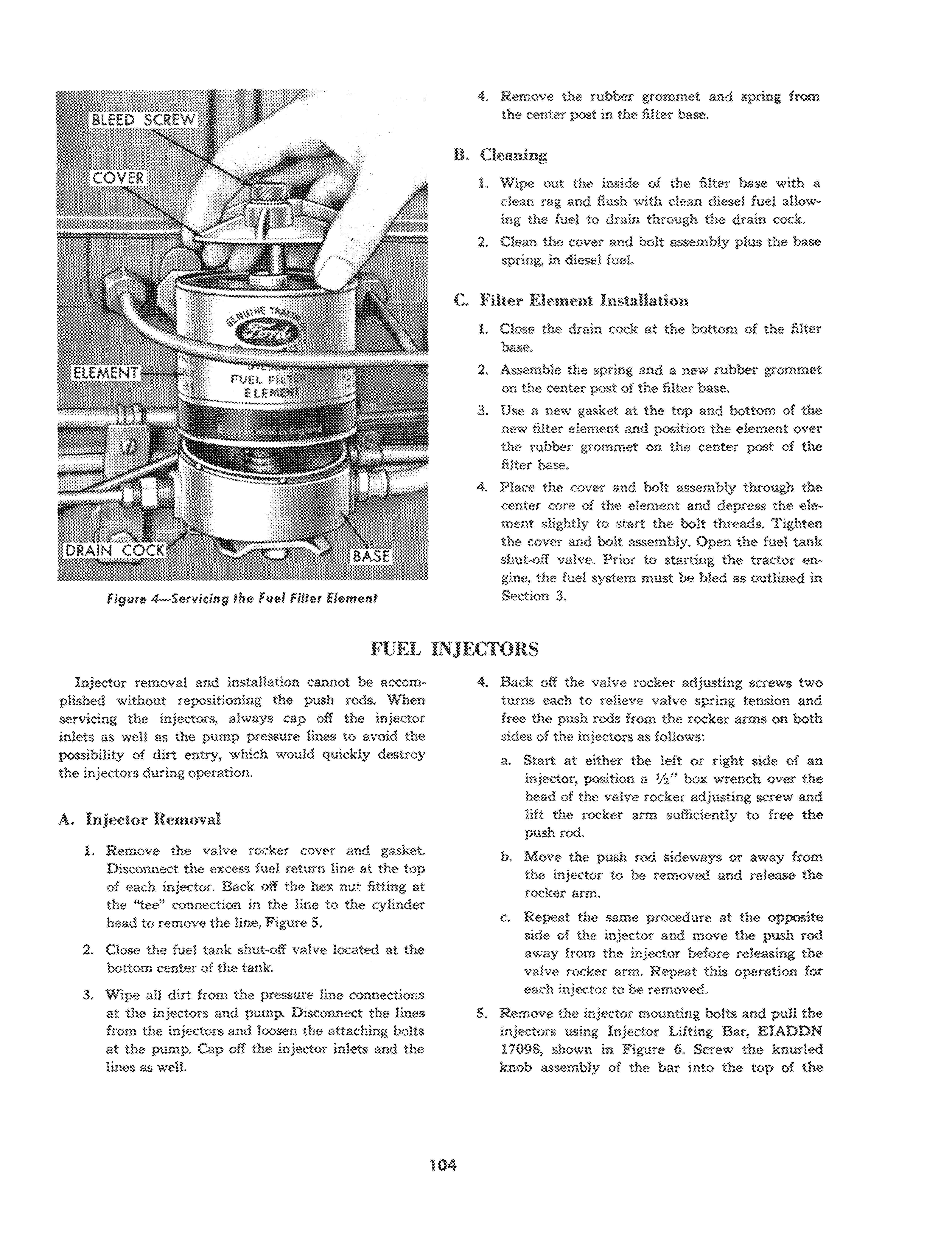
Figure 4-Servititlg the Fuel Filter Element
4. Remove the rubber grommet and spring from the center post in the niter base.
B. Cleaning
1. Wipe out the inside of the filter base with a dean rag and flush with dean diesel fuel allowing the fuel to drain through the drain cock. 2. Clean the cover and holt assembly plus the base spring, in diesel fuel.
C. Filter Element Installation
1. Close the drain cock at the hottom of the filter base. 2. Assemble the spring and a new rubber grommet on the center post of the filter base. 3. Use a new gasket at the top and bottom of the new filter element and position the element over the rubber grommet on the center post of the filter base. 4. Place the cover and holt assembly through the center core of the element and depress the element slightly to start the holt threads. Tighten the cover and holt assembly. Open the fuel tank shut-off valve. Prior to starting the tractor engine, the fuel system must be bled as outlined in
Section 3.
Injector removal and installation cannot be accomplished without repositioning the push rods. When servicing the injectors, always cap off the injector inlets as well as the pump pressure lines tn avoid the possibility of dirt entry, which would quickly destroy the injectors during operation.
A. Injector Removal
1. Remove the valve rocker cover and gasket.
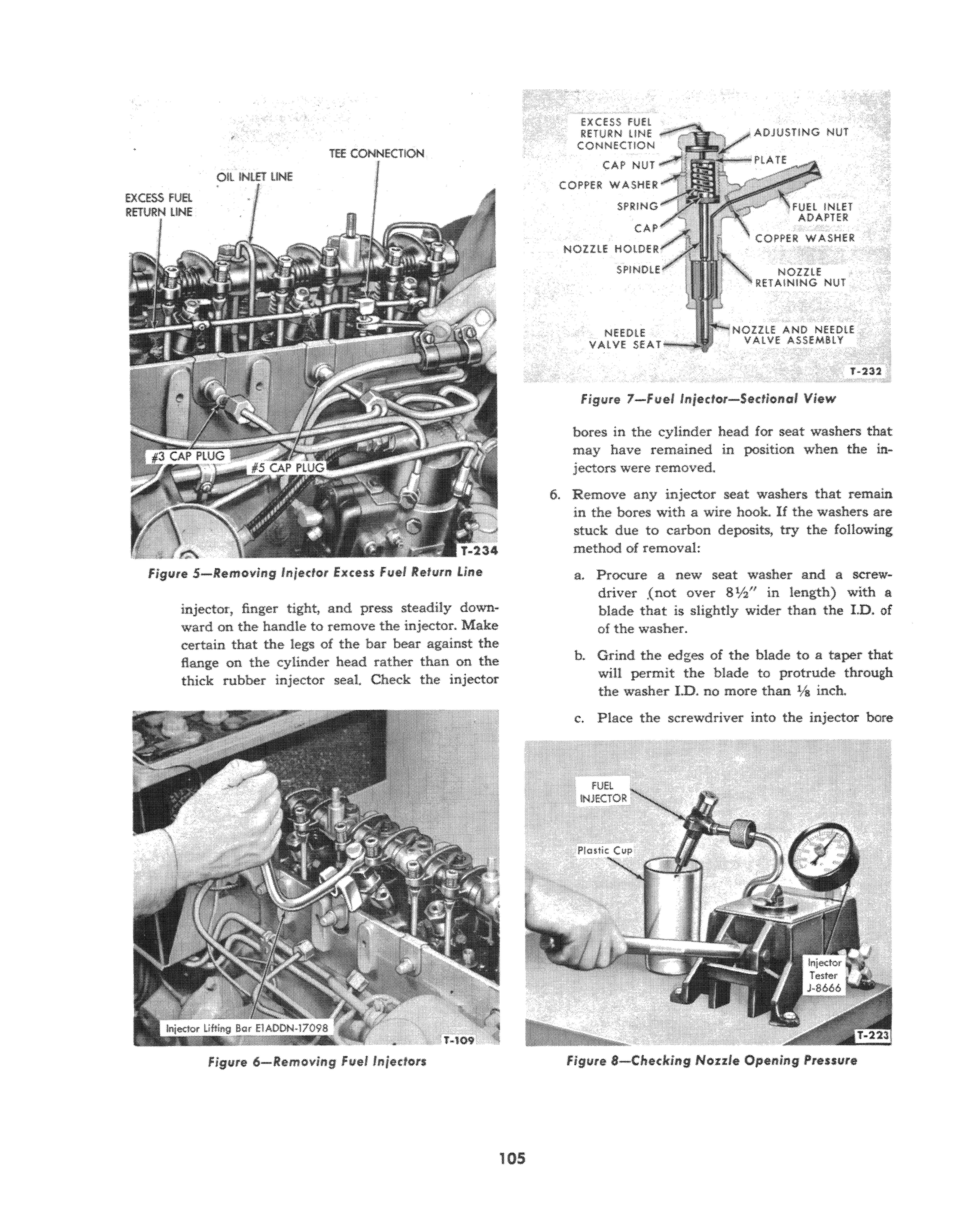
Disconnect the excess fuel return line at the top of each injector. Back off the hex nut fitting at the "tee" connection in the line to the cylinder head to remove the line, Figure 5. 2. Close the fuel tank shut-off valve located at the bottom center of the tank.
3. Wipe all dirt from the pressure line connections at the injectors and pump,. Disconnect the lines from the injectors and loosen the attaching bolts at the pump, Cap off the injector inlets and the lines as well. 4. Back off the valve rocker adjusting screws two turns each to relieve valve spring tension and free the push rods from the rocker arms on both sides of the injectors as follows: a. Start at either the left or right side of an injector, position a 112" box wrench over the head of the valve rocker adjusting screw and lift the rocker arm sufficiently to free the push rod. b. Move the push rod sideways or away from the injector to be removed and release the rocker arm. c. Repeat the same procedure at the opposite side of the injector and move the push rod away from the injector before releasing the valve rocker arm. Repeat this operation for each injector to be removed. S. Remove the injector mounting bolts and pull the injectors using Injector Lifting Bar, EIADDN 17098, shown in Figure 6. Screw the knurled knob assembly of the bar into the top of the
Oil !NI.Ei tiNE TEE CONNECTtON
FiglJte 5-Removing Injector .Excess fuel Refurn Line
injector, finger tight, and press steadily downward on the handle to remove the injector. Make certain that the of the bar bear against the flange on the cylinder head rather than on the thick rubber injector seal. Check the injector

<;:AP NUT
COPPER WASHER
CA
NOZZlE HOlDER
NEWlE VALVE SEAT
Figllre 7-Fuet Injector-Sectioned View
bores in the cylinder head for seat washers that may have remained in position when the jectors were removed. 6. Remove any injector seat washers that remain in the 'bores with a wire hook. If the washers are stuck due to carbon deposits, try the following method of removal:
a. Procure a new seat washer and a screwdriver .(not over 8Vz" in leogth) with a blade that is slightly wider than the I.D. of of the washer.
b. Grind the edges of the blade to a taper that will permit the blade to protrude through the washer 1.0. no more than % inch.
c. Place the screwdriver into the injector bore
figure 6-Removing fllel Injectors Figure 8-Cheddng Nozzle Opening Pressure
and guide the tapered edges into the stuck washer. d. Tap the screwdriver handle sharply so that the blade bites into the washer then twist the screwdriver to free the washer.
B. Injector Tests
It is recommended that the injectors be tested before disassembly, as well as after being reassembled. Before testing, dean the outside of the injector with a good grade of carbon solvent and Brass Wire Brush 18537-27.
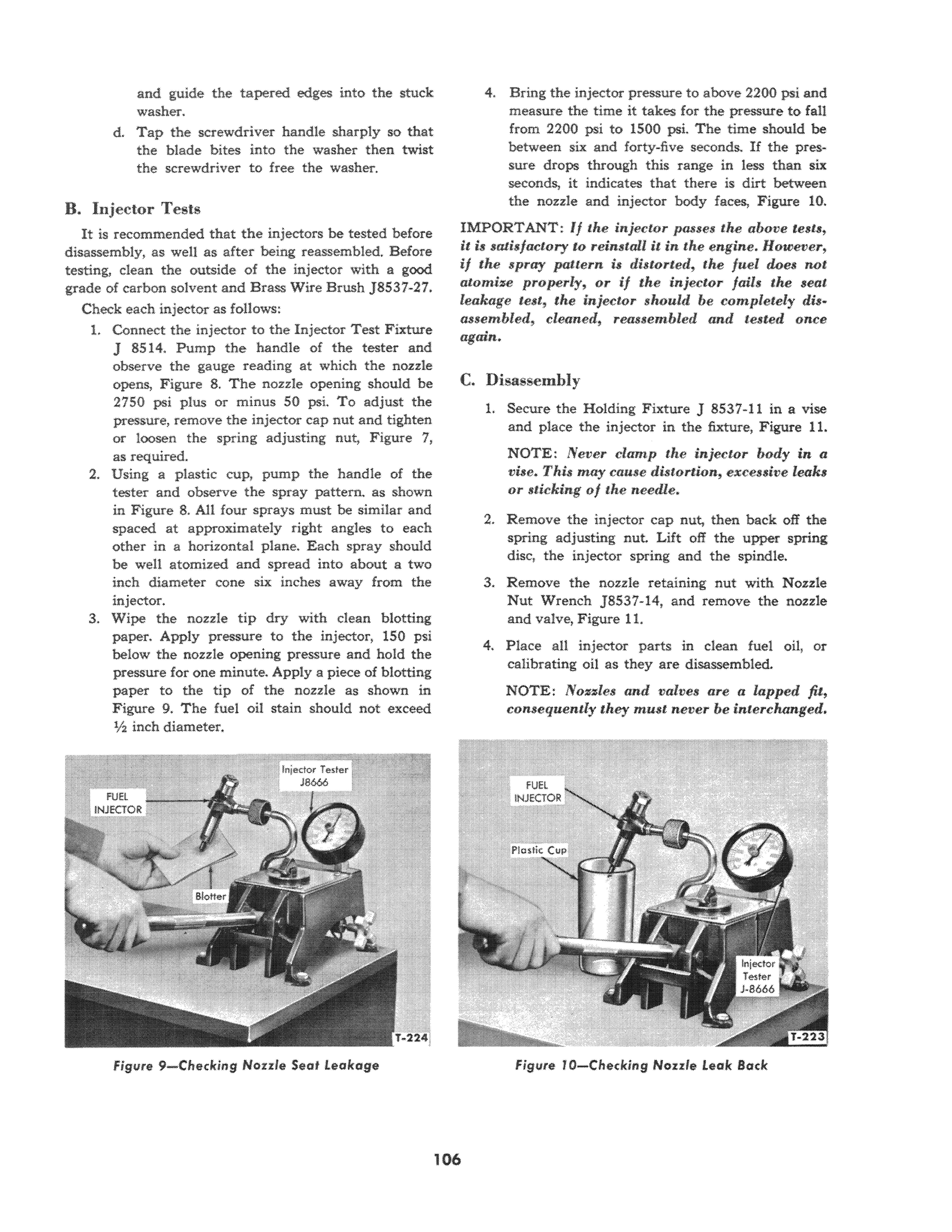
Check each injector as follows: 1. Connect the injector to the Injector Test Fixture J 8514. PUmp the handle of the tester and observe the gauge reading at which the nozzle opens, Figure 8. The nozzle opening should be 2750 psi plus or minus 50 psi. To adjust the pressure, remove the injector cap nut and tighten or loosen the spring adjusting nut, Figure 7, as required. 2. Using a plastic cup, pump the handle of the tester and observe the spray pattern. as shown in Figure 8. All four sprays must be similar and spaced at approximately right angles to each other in a horizontal plane. Each spray should be well atomized and spread into about a two inch diameter cone six inches away from the injector. 3. Wipe the nozzle tip dry with dean blotting paper. Apply pressure to the injector, 150 psi below the nozzle opening pressure and hold the pressure for one minute. Apply a piece of blotting paper to the tip of the nozzle as shown in Figure 9. The fuel oil stain should not exceed V2 inch diameter.
4. Bring the injector pressure to above 2200 psi and measure the time it takes for the pressure to fail from 2200 psi to 1500 psi. The time should be between six and forty-five seconds. If the pressure drops through this range in less than six seconds, it indicates that there is dirt between the nozzle and injector body faces, Figure 10. IMPORTANT: If the injector passes the above tesl$, it is satisfactory to reinstall it in the engine. However, if the spray pattern is distorted, the juel does nQt atomize properly, or if the injectQr fails the seat leakage test, the injector slwuld be completely disassembled, cleaned, reassembled and tested once again.

C. Disassemhly
L Secure the Holding Fixture 1 8537-11 in a vise and place the injector in the fixture, Figure I I.
NOTE: lVever clamp tlte injecwr Imdy in a vise. Thu may cause distortion, excessive leaks or stieking oj the needle.
2. Remove the injector cap nut, then back off the spring adjusting nut. Lift off the upper spring disc, the injector spring and the spindle. 3. Remove the nozzle retaining nut with Nozzle
Nut Wrench J8537-14, and remove the nozzle and valve, Figure 11. 4. Place all injector parts in clean fuel oil, or calibrating oil as they are disassembled.
NOTE: Nozzles and valves are (I lapped fit, consequently they must never be interchanged.
figure 9- Checking Norrie Seat Leakage Figure 10-Cheddng Nonie Leak 80:ek
figure f I-Removing Noule Retaining Nut
D. Cleaning
Use tools in Injector Nozzle Service Kit J8537 to remove all carbon from the nozzle and interior of the nozzle as outlined in the following steps;
1. Carbon deposits formed in the spray holes, and needle tip, should be softened by soaking the needle and nozzle in a carbon solvent for a short period Then, use a soft wire brush to remove aU carbon from the needle and nozzle exterior. It is important that the nozzle and needle be rinsed in clean fuel oil immediately after soaking in the carbon solvent to prevent corrosion on the highly finished surfaces.

2. Clean the pressure chamber of the nozzle with the 0.043'1 Pressure Chamber Drill J8537-4,
Figure 12.
3. Clean the spray holes in the nozzle with the 0.009" Cleaning Wire J8537-1 and the Pin Vise figure t 3-Cleaning Noule Discharge Holes
J4298-1. The wire should protrude from the vise just enough to pass through the holes in the nozzle to prevent breaking the wire. Rotate the vise slowly without applying undue pressure to the cleaning wire, Figure 13.
4. The seats are deaned by rotating the Carbon
Remover J8537-18 in the nozzle, Figure 14.
Then, carefully clean the upper chamber with the same remover.
5. The annular groove in the top of the nozzle and the pressure chamber groove in the nozzle are cleaned with the Pressure Chamber Carbon
Remover J8537-15, Figure 15.
6. Steps one through five have outlined the procedure for removing carbon from the nozzie. The nozzle and needle must be thoroughly back flushed to remove all the loosened carbon deposits. Place the Reverse Flush Nozzle Adapter J8537-6 on the injector tester. Then, position the nozzle and valve in the adapter, tip end first, and secure with the knurled nut. Rotate the
figure 12-C/eaning Nou/e Pressure Chamber Figure 14-Cleaning Norde Seats
figure 15- Cleaning Annuler Groove in Nozzle
needle in the nozzle while Hushing to make sure it is free.
7. After the nozzle is thoroughly back flushed to remove all loose carbon, the seat can be polished by placing a very sman amount of tallow on the end of a Polishing Stick and rotating it in the nozzle, Figure 16. 8. If the back-leakage test was slower than fortyfive seconds, or the valve sticks slightly, this can be corrected by remating the needle and the nozzle assembly, as shown in Figure 17. This is accomplished by using the special polishing compound consisting of tallow and a small amotIDt of the finest lapping compotIDd, Kent-
Moore Part No. J8537-28, and then following one of the two methods given below. a. Hold needle in chuck and polish with a piece of felt, coated with a very small amount of the above compound. b. Place the nozzle in a drill chuck having a maximum rpm of 450. Apply a small quantity of the compound on the needle body, insert the needle in the body and turn it to lap. Hold the needle up off the pressure chamber shoulder while lapping to avoid damage to the needle. Care should be exercised so that the lapping compound does not damage the needle seat.

9. The assembly must be thoroughly washed, back flushed with diesel fuel and cleaned after lapping.
E. Assembly
All injector parts should be reassembled wet after rinsing in dean fue! oil or calibrating oil.
1. Normally the injector inlet adapter need not be removed from the injector body. However, if the adapter is removed, it will be necessary to use a new copper washer to ensure a proper seal.
Install and tighten the adapter in the injector body.
2. Position the nozzle a.nd needle valve on the injector body, making certain that the dowel pins in the body are installed correctly in the nozzle. Position the nozzle retaining nut over the nozzle and tighten to 50 ft. Ibs. torque with
Nozzle Nut Wrench J8537-14. It will be necessary to place the injector in the Holding Fixture
figure 16-Polishing Nozzle Seats
figure 17-Lapping Needle in Norde


