9 minute read
TROUBLE SHOOTING
The ignition system is composed of a primary and a secondary circuit, The battery, ignition switch, primary coil winding, distributor points, condenser, and primary wiring are in the primary circuit. The secondary winding of the coil, rotor, distributor cap, high tension wiring and spark plugs compose the secondary circuit.
A. No Spark At Any SI)ark Plug Wire
This indicates trouble in the primary circuit, in the rotor or in the high tension wire between the coil and the distributor.
1. Turn the ignition switch on, Hold the end of one spark plug wire % 6 inch from the cylinder head while the engine is being cranked. Repeat this procedure in turn at each spark plug wire.
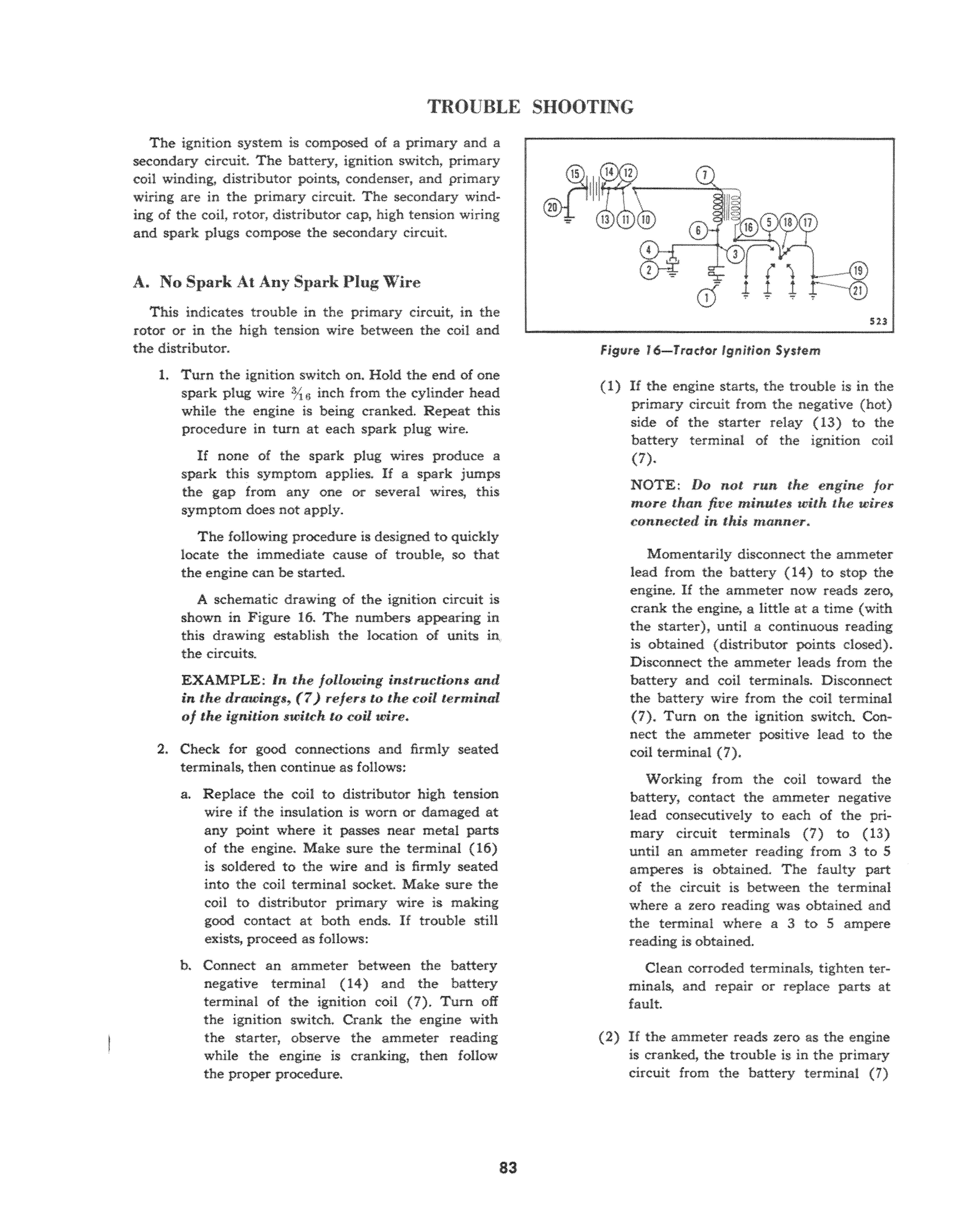
If none of the spark plug wires produce a spark this symptom applies. If a spark jumps the gap from anyone or several wires, this symptom does not apply. The fonowing procedure is designed to quickly locate the immediate cause of trouble, so that the engine can be started. A schematic drawing of the ignition circuit is shown in Figure 16. The numbers appearing in this drawing establish the location of units the circuits.
EXAMPLE: In the following instructions and in the drawings, (7) refers to the coil terminal of the ignition switch to coil wire.
2. Check for good connections and firmly seated terminals, then continue as follows: a. Replace the coil to distributor high tension wire if the insulation is worn or damaged at any point where it passes near metal parts of the engine. Make sure the terminal (16) is soldered to the wire and is firmly seated into the coil terminal socket. Make sure the coil to distributor primary wire is making good contact at both ends. If trouble still exists, proceed as follows: b. Connect an ammeter between the battery negative terminal ( 14 ) and the battery terminal of the ignition coil (1). Tum off the ignition switch. Crank the engine with the starter, observe the ammeter reading while the engine is cranking, then follow the proper procedure.
Figure 16-Trado( Ignitiort System
523
(1) If the engine starts, the trouble is in the primary circuit from the negative (hot) side of the starter relay (13) to the battery terminal of the ignition coil (1).
NOTE: Do not run lhe englne for more than five minutes with the wires in this manner.
Momentarily disconnect the ammeter lead from the battery (14) to stop the engine. If the ammeter now reads zero. crank the engine, a little at a time (with the starter), until a continuous reading is obtained (distributor points closed). Disconnect the ammeter leads from the battery and coil terminals. Disconnect the battery wire from the coil terminal (7). Tum on the ignition switch. Connect the ammeter positive lead to the coil terminal (7).
Working from the coil toward the battery, contact the ammeter negative lead consecutively to each of the primary circuit terminals (7) to (13) until an ammeter reading from 3 to 5 amperes is obtained. The faulty part of the circuit is between the terminal where a zero reading was obtained and the terminal where a 3 to 5 ampere reading is obtained.
Clean corroded terminals, tighten terminals, and repair or replace parts at fault.
(2) If the ammeter reads zero as the engine is cranked, the trouble is in the primary circuit from the battery terminal (7)
of the coil to the grounded side (1) of the distributor contact points.
Ground the condenser insulated terminal (4). If the ammeter now reads zero, make sure the coil to distributor primary wire is not broken and that it is making good contact at both ends (6) and (3). If the ammeter still reads zero, replace the coil.
If the ammeter reads 3 to 5 amperes when the condenser is grounded, the trouble is in the distributor points or the primary circuit contact (3) to the breaker arm assembly. Replace or adjust the distributor points, or repair the primary circuit contact (3).
(3) If the engine does not start and the ammeter reads from 3 to 5 amperes as the engine is cranked, the trouble is in the condenser or the ignition secondary circuit.
Tighten the ignition condenser terminal screws (2) and (4). Remove the high tension wire (16) from the coil. Connect a jumper wire into the high tension terminal (16) of the coil. Hold the other end of this jumper wire 'Yl6 inch from the cylinder head while the engine is cranked with the starter.
If there is no spark, remove the condenser for test, or replace it with one known to be good. If this has not corrected the trouble, replace the coil.

(4) If the spark from the jumper wire is satisfactory, the trouble is a grounded secondary circuit in the distributor rotor or distributor cap. Remove and test the rotor. Replace the rotor if the test indicates high tension circuit leaks due to carbon tracks or due to cracked insulation between the electrode and the distributor shaft. Also make certain that the rotor spring is contacting the brush in the center of the distributor cap. If the rotor is satisfactory, carefully examine the distributor cap for carbon tracks to the distributor housing, due to moisture or foreign matter. Clean the cap with lacquer thinner. Replace the cap if it has carbon tracks. B. Satisfactory Spark From Some But Not All
Spark Plug Wires
The trouble lies within the distributor cap or remainder of the secondary circuit to the spark plugs_
1. Test the spark from the end of each spark wire at idle speed. The spark should jump a. % (lit gap continuously. A spark that fails tt.. jump this gap regularly. without missing, considered a weak spark.
DEFINITION: A satisfactory spark is (me thar. will, without regularly jump a spark. gap equivalent to the resistance o/Jeretl by ,. correctly spaced ,'park plug untler the com_ pression pressure encountered in the opera_ tion of the engine.
The fact that a satisfactory spark is obtained from some spark plug wires eliminates fro!l). consideration those ractors that affect equallythe output of an the spark plug wires, which are the primary circuit and the secondary circuit through the coil and high tension coil wire, up to the distributor rotor and cap.
The following procedure takes into account each of the factors that could account for this symptom, in the order of their probability.
The numbers appearing in drawing, Figure 15, of the ignition circuit, establish location of the terminals referred to in the text.
2. An unsatisfactory spark at some but not all of the spark plug wires indicates faulty installation or serious resistance (air gap) in the high ten. sion circuit.
a. Replace spark plug wires if the insulation is damaged. Make sure all spark plug wires are soldered to their terminals. Make sure the spark plug wire terminals and the terminal sockets are free from corrosion and the wires are firmly seated in the distributor cap. If the above procedure has not corrected the trouble proceed as follows:
b. Remove the distributor cap, then clean the cap with lacquer thinner. Replace the dis. tributor cap if it is burned, cracked, or has carbon tracks. Make sure the spark plug wires seat firmly in the sockets.
c. Check the rotor for proper fit on the shaft and for proper clearance to distributor cap terminals.
C. Intermittent Slla:rk At AU Spark Plugs
The trouble is in the primary circuit or coil to tributor lead.
1. Test the spark from the end of each spark plug wire at idle A spark that fails to jump a 14 kilovolt spark setting continuously, is considered an intermittent spark and the following procedure applies. When the spark delivered at the end of the spark plug wire is satisfactory but intermittent, the primary ignition circuit is logically given first consideration in the diagnosis procedure.
The fact that between "misses" the spark is satisfactory, precludes the possibility that the trouble is in the secondary circuit. The exception would be in relatively rare cases of intermittent breakdown of the insulation in the coil, or when moisture, oil or foreign matter is allowed to accumulate in sufficient quantity on the distributor cap or distributor rotor to conduct the high tension circuit intermittently to ground. The numbers in the following text refer to the terminals in Figure 16. 2. Tighten aU connections, replace or adjust the contact points, test the coil and test the condenser. a, Tighten all connections in the primary cir· cuit, including both terminals of the condenser (2) and (4) and both ends of both battery cables (13), (14), (15) and (20), Tighten the ignition s'W'ltcn terminals ( 10) and (11). Make sure the coil to distributor high tension wire terminal (16) is soldered to the wire and seated all the way into the high tension terminal of the coit Make sure that the high tension wire socket in the coil is not dirty or corroded. If the trouble still exists, proceed as follows: b. Replace or the distributor points if required. Make sure the breaker arm is not binding on its bearing and the spring tension is correct. Reset the timing, and again test the quality of the spark. If the spark is still intermittent, test the coil and condenser.

c. Test the condenser capacity, leakage, and series resistance. If the coil and condenser are both satisfactory, examine the distributor cap, housing, and rotor for moisture, oil, or foreign matter which might cause an intermittent leak of high tension current to ground. Remove oil and roreign matter with lacquer and the parts having carbon runs imbedded in the surface.
D. Weak SI)ark At AU Spark Plug Wires
The trouble lies in the primary circuits, distributor rotor or coil high tension wire. A weak spark at all plugs is caused by units that have an equal effect on all the wires.
1. With the engine idling, test the quality of the spark from the end of each spark plug wire. The spark should jump a 14 kilovolt gap (about inch). This test assures sufficient spark energy at the spark plug terminals when under 120 pounds compression, If the spark jumps this gap regularly without missing, it is satisfactory. If a satisfactory spark is obtained from some but not all spark plug wires, refer to the symptom "Satisfactory Spark From Some But Not All Spark
Plug Wires." The following procedure applies only where a weak spark is obtained from all of the spark plug wires. The entire primary circuit, including the distributor points, has an equal effect at all spark plug wires. The condenser, coil, distributor rotor and rotor gap have an equal effect at all spark plug wires, The high tension wire from the coil to the distributor also influences the output of all plug wires. These units control spark intensity.
It is possible for all spark plug wires or all terminals to leak, however, this is considered unlikely. For this reason, tbe following procedure considers the more probable causes first, in the order of their accessibility. 2. Since the ignition secondary output is dependent on the primary voltage, the condition or state of charge of the battery is an important consideration. If the battery will not crank the engine, recharge or replace the battery, a. The ignition primary circuit is tested in two steps as foHows: (1) Measure the distributor point dwelL (2) If the dwell is within 27"-31", proceed with (b) "Test Battery To Coil Resistance."
NOTE: When the points are new, be sure to also check the gap setting with a feeler gauge (O.024-Q'()26).
If the dwell is not within these limits, replace points that are visibly burned or pitted, then adjust the points to obtain


