7 minute read
MANIFOLD, MUFfLER AND EXHAUST PIPE
3. Disconnect the fuel line at the fuel shut-off valve fitting. 4. Remove the fuel tank attaching bolt from each rear corner of the fuel tank.
5. Loosen the nut that attaches the front of the fuel tank to the center of the fuel tank front support bracket. 6. Disconnect the wire from the fuel gauge at the tank.
7. Slide the fuel tank approximately one inch to free it from the front mounting bolt. then lift it from the tractor.
B. Fuel Tank Cleaning
1. Water caused by normal condensation, accumulates in the fuel tank when allowed to stand low or empty for a period of time (usually over night). Therefore, it is a good practice to fill the tank to capacity at the end of each day of operation to prevent moisture laden air from forming water, rust and gum formations. Long periods of tractor storage may also cause gum formations in the tank.
2. If it is necessary to clean the tank, drain the fuel completely and remove the shut-off valve fitting.
3. Wash the interior of the tank thoroughly with a mixture of alcohol and acetate or any other suitable solution. Disassemble the fuel shut-off valve and dean it thoroughly. Dry the tank thoroughly. then reassemble the shut-off valve and mount it on the tank.
C. Sediment Bowl and Fuel Lines
1. The sediment bowl is located at the front of the carburetor and is provided for the purpose of trapping condensation or other contaminants that may flow through the fuel line from the fuel tank. 2. The fuel line can be removed for cleaning or replacement by first disconnecting the line at the fuel tank and the sediment bowL
3. To clean the fuel line, blow it out with compressed air. When replacing a fuel line, be sure that the connections are tight and do not leak.
NOTE; Tighten fuel linecmmecti<ms carefully. The fittings are brass and it is possible to strip the threads if they are over-tightened.
4. To clean the sediment bowl, turn the fuel tank shutoff valve to the "OFF" position. Loosen the bail nut and remove the bail from the bowl.
Withdraw the bowl from the top of the housing and also remove the screen. Clean both the screen and the bowl and then replace them. Use a new gasket between the sediment bowl and sediment bowl housing.
D. Fuel Tank Installation
1. Place the fuel tank in position on the tractor making sure the carriage bolt on the fuel tank front support bracket engages the fuel tank bracket.
2. Install the bolt and lock washer at each rear corner of the tank.
3. Tighten the nut at the fuel tank front support bracket.
4. Insert the oil gauge line in the clip at the right rear of the fuel tank.
5. Connect the wire to the terminal on the fuel gauge tank unit.
6. Connect the fuel line at the fuel shut-off valve fitting and tum the fuel shut-off valve to the "ON" position. Be sure that there are no fuel leaks.
7. Install the hood assembly.
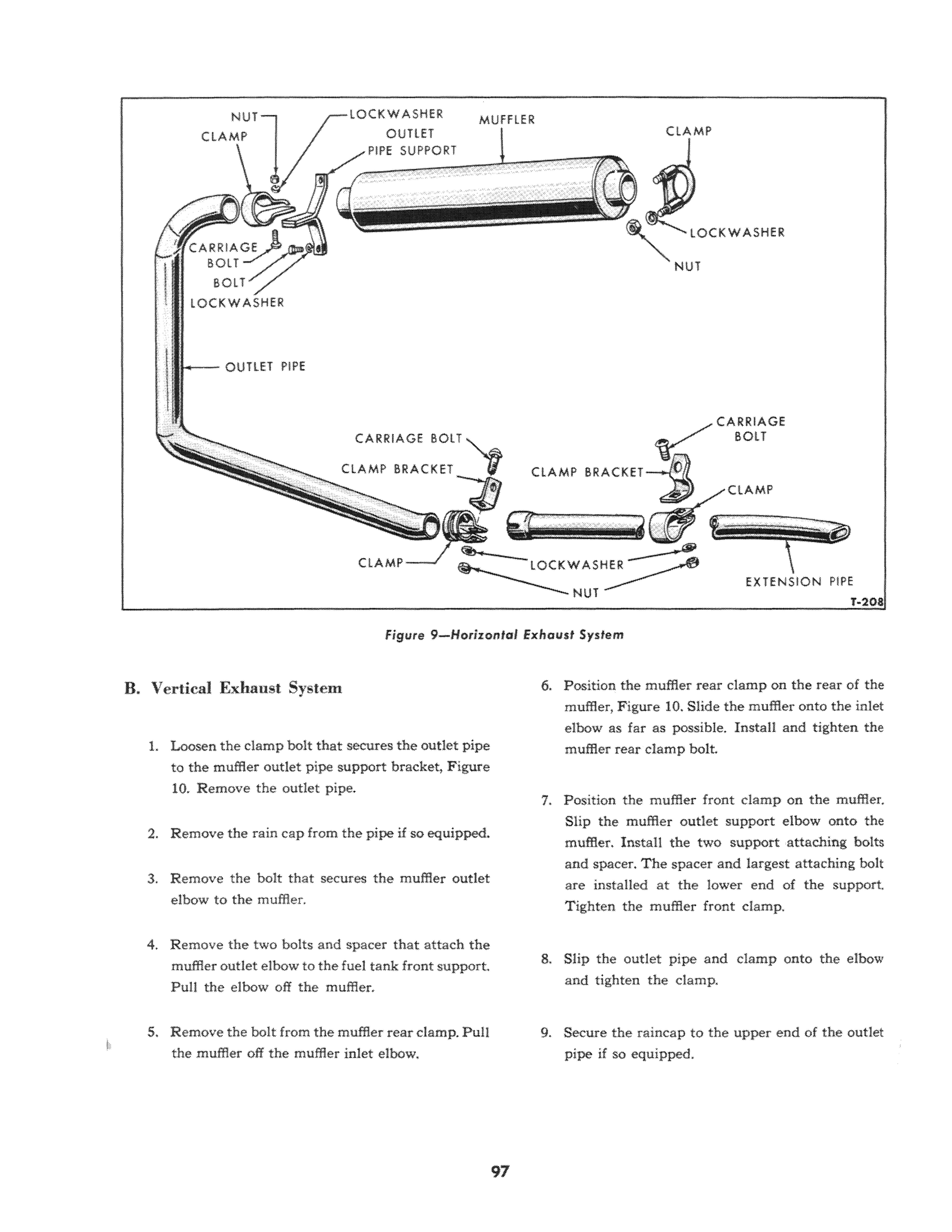
The intake and exhaust manifolds are an integral unit on Ford Tractors witi: gasoline or LP-Gas engines. The manifold and exhaust systems are shown in Figures 9 and 10. A vertical or horizontal exhaust system is available on all models. All mufflers mount directly on the exhaust manifold for convenience in replacing. A. Removal MANU"'OLD
1. Close the fuel tank shut-off varve under the tank.
2. Remove the two bolts, nuts and lock washers from the muffler inlet elbow and disconnect it from the manifold.
3, Disconnect the fuel line at the carburetor sediment bowl and the air intake tube at the carburetor.
4. Remove the six nuts and lock washers from the manifold mounting studs.
5. Remove the manifold assembly and the manifold gasket from the engine.
8. Disassembly, Inspection and Cleaning
If the manifold has been in use for some time, deposits of gum may he present in the intake manifold. These deposits affect the air-fuel mixture flow characteristics and may cause poor engine performance. It is good practice to dean the manifold thoroughly every time it is removed from the engine.
1. Remove the two nuts and lock washers from the carburetor mounting studs and separate the carburetor from the manifold. Be sure the carburetor mounting gasket is also removed.
2. Examine the manifold for cracks or defects such as warpage, or chips out of the mounting surface.
Always replace a warped or cracked manifold.
Soak the manifold in a good solvent to loosen gum deposits, then dry it thoroughly.

3. Place a new carburetor mounting gasket on the carburetor mounting studs, then install the carburetor and the nuts and lock washers. Tighten the nuts securely.
C. Installation
Be sure all the old gasket material is cleaned off the mounting surfaces on the manifold and cylinder head. Always use new manifold gaskets whenever the manifold is removed.
1. Position the manifold gasket, and the manifold, over the mounting studs.
2. Install the six nuts and lock washers and tighten the center nuts first. Then alternately tighten the remaining nuts toward each end to 40-50 ft, lbs. torque.
3. Place a new gasket between the manifold and the muffler inlet elbow and install the two bolts.
Tighten the bolts to 40-50 ft. Ibs. torque. 4. Connect the fuel line at the carburetor sediment bowl and the air intake tube at the carburetor.
Open the fuel tank shut-off valve and check for leaks at the carburetor.
MUFFLER, OUTLET AND EXTENSION PIPE REPLACEMENT
A. Horizontal Exhaust System
1. Remove the bolt that attaches the muffler outlet pipe extension bracket and damp ro the center housing, see Figure 9.
2. Remove the bolt that attaches the outlet and extension pipe clamp bracket to the engine plate located at the front of the transmission. Remove the bolt that attaches the damp to the pipes.
3. Separate the extension pipe from the outlet pipe.
4. Remove the bolt that attaches the muffler front clamp to the muffler outlet pipe support.
5. Separate the muffler outlet pipe from the muffler.
6. Remove the two bolts that attach the muffler front support to the fuel tank front support and remove the muffler front support.
7. Remove the clamp that secures the muffler to the muffler inlet flange elbow.
8. Separate the muffler from the elbow.
9. Slip the muffler onto the muffler inlet flange el. bow, Figure 9. Secure the muffler to the elbow with the rear clamp.
10. Secure the muffler outlet pipe support to the fuel tank front support with the two attaching bolts.
11. Slip the muffler front clamp on the outlet pipe.
Insta.ll the muffler outlet pipe on the muffler. Secure the front clamp to the muffler front support with a bolt, lock washer and nut.
12. Slip the extension pipe onto the outlet pipe, then install the attaching clamps and brackets.
CLAMP
lOCKWASHER
! ..... OUTlET PIPE
CARRIAGE 80l T "-..IS!. CLAMP 8RACKET 71 CLAMP 8RACKET CARRIAGE SOlT
CLAMP
Figure 9- Horizontal Exhaust System

EXTENSION P1PE
T-208
B. Vertical Exhaust System
1. Loosen the clamp bolt that secures the outlet pipe to the muffler outlet pipe support bracket, Figure 10. Remove the outlet pipe.
2. Remove the rain cap from the pipe if so equipped.
3. Remove the bolt that secures the muffler outlet elbow to the muffler.
4. Remove the two bolts and spacer that attach the muffler outlet elbow to the fuel tank front support.
Pull the elbow off the muffler.
5. Remove the bolt from the muffler rear clamp. Pull the muffler off the muffler inlet elbow. 6. Position the muffler rear clamp on the rear of the muffler, Figure 10. Slide the muffler onto the inlet elbow as far as possible. Install and tighten the muffler rear damp bolt.
1. Position the muffler front damp on the muffler.
Slip the muffler outlet support elbow onto the muffler. Install the two support attaching bolts and spacer. The spacer and largest attaching bolt are installed at the lower end of the support.
Tighten the muffler front damp.
8. Slip the outlet pipe and damp onto the elbow and tighten the damp.
9. Secure the raincap to the upper end of the outlet pipe if so equipped.


