2 minute read
FUEL FILTER
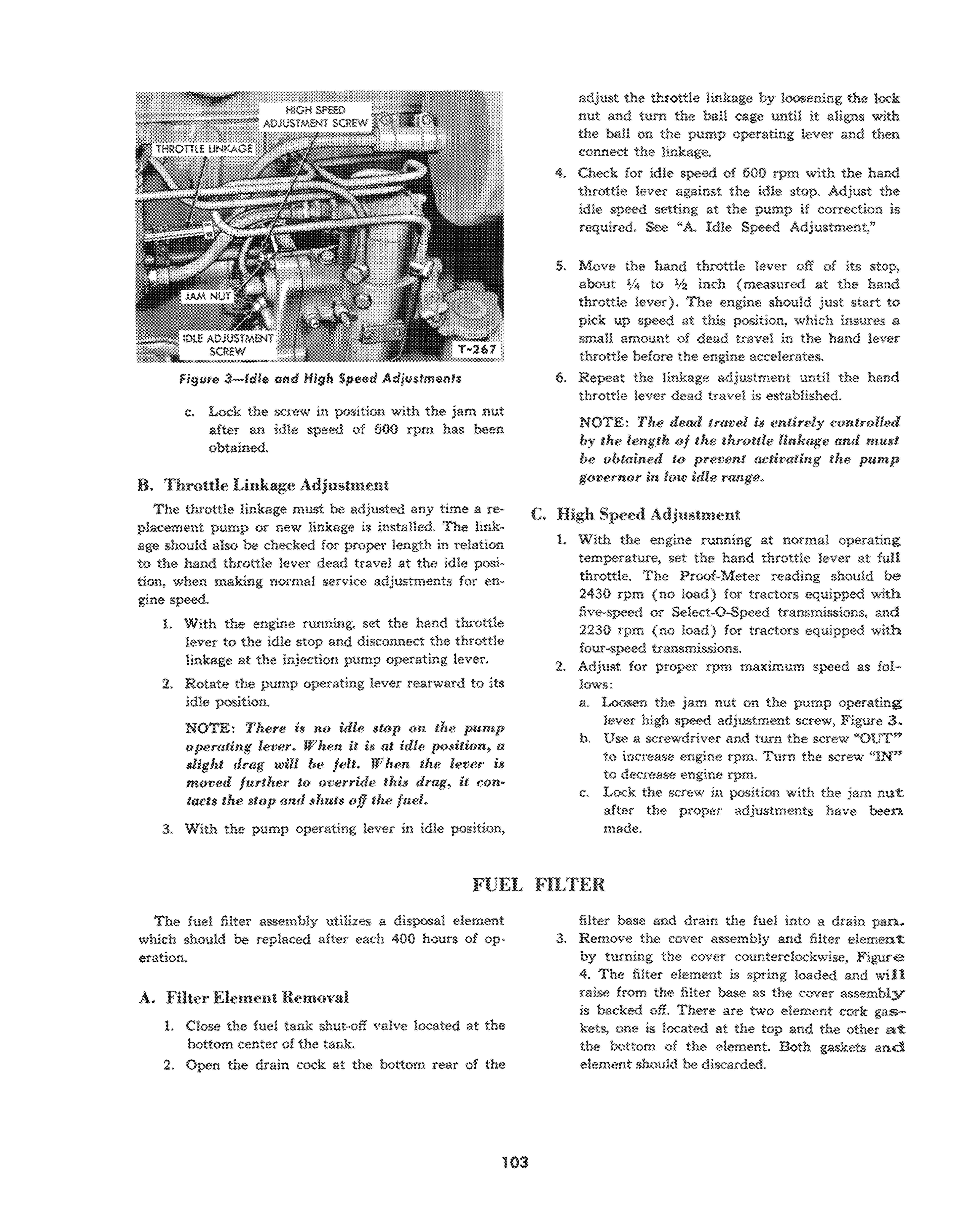
Figure 3-ldle and High Speed Adjustments
c. Lock the screw in position with the jam nut after an idle speed of 600 rpm has been obtained.
B. Throttle Linkage Adjustment
The throttle linkage must be adjusted any time a replacement pump or new linkage is installed. The linkage should also be checked for proper length in relation to the hand throttle lever dead travel at the idle position, when making normal service adjustments for engine speed. 1. With the engine running, set the hand throttle lever to the idle stop and disconnect the throttle linkage at the injection pump operating lever. 2. Rotate the pump operating lever rearward to its idle position. NOTE: There is no idle stop on the pump operating lever. When it is at idle position, a slight drag will be felt. When the lever is moved further to override litis drag, it contacts the stop and shuts 00 the fuel.
3. With the pump operating lever in idle position,
adjust the throttle linkage by loosening the lock nut and turn the ball cage until it aligns with the ball on the pump operating lever and then connect the linkage. 4. Check for idle speed of 600 rpm with the hand throttle lever against the idle stop. Adjust the idle speed setting at the pump if correction is required. See "A. Idle Speed Adjustment,"
5. Move the hand throttle lever off of its stop, about 1/4 to V2 inch (measured at the hand throttle lever). The engine should just start to pick up speed at this position, which insures a small amount of dead travel in the hand lever throttle before the engine o.ccelerates. 6. Repeat the linkage adjustment until the hand throttle lever dead travel is established.
NOTE: The dead travel is entirely controlled by the length. of the throttle linkage antI must be obtained to prevent actit'ating the pump governar in low idle range.
c. High Speed Adjllstlnent
1. With the engine running at normal operating temperature, set the hand throttle lever at full throttle. The Proof-Meter reading should be 2430 rpm (no load) for tractors equipped with five-speed or Select-O-Speed transmissions, and 2230 rpm (no load) for tractors equipped with four-speed transmissions. 2. Adjust for proper rpm maximum speed as follows: a. Loosen the jam nut on the pump operating lever high speed adjustment screw, Figure 3. b. Use a screwdriver and turn the screw "OUT" to increase engine rpm. Turn the screw "IN" to decrease engine rpm. c. Lock the screw in position with the jam nut: after the proper adjustments have been made.
The fuel filter assembly utilizes a disposal element which should be replaced after each 400 hours of operation.
A. Filter Element Removal
1. Close the fuel tank shut-off valve located at the bottom center of the tank. 2. Open the drain cock at the bottom rear of the
filter base and drain the fuel into a drain pan. 3. Remove the cover assembly and filter element: by turning the cover counterclockwise, Figure 4. The filter element is spring loaded and will raise from the filter base as the cover assembly is backed off. There are two element cork gaskets, one is located at the top and the other at: the bottom of the element. Both gaskets and element should be discarded.


