14 minute read
GENERATOR AND CHARGING CIRCUIT
charge the battery and repeat the test. Likewise if all cell readings are less than 1.95 volts, charge the battery and repeat the test. 6. If cell readings are 1.95 volts or more and vary more than 0.5 volt, replace the battery. 7. A battery that is in good condition should be charged until a hydrometer reading of 1.2301.275 is obtained. 8. Connect the secondary wire to the coil if it was previously disconnected.
E. Charging the Battery
1. Wash all dirt from the battery and clean its terminals before placing it on charge. Do not allow dirt to enter the cells. Bring the liquid level in the cells up to the fill ring. Allow the battery to warm up before adding water as the level will rise as it warms. 2. Slow charging is the only method which will iuIIy charge a battery. Slow charging should be at a rate of 3 to 4 amperes for a sufficient length of time to funy charge the battery. The battery is fully charged when the cells are all
gassing freely and the gravity ceases to rise for three successive readings taken at hourly intervals. Do not stop charging short of the fully charged state, even if it requires charging for 24 hours or more. A battery which is badly sulphated may not take a charge or will require more charging time than a normal battery. 3. A fast charger has the ability to quickly "boost" a battery without removing it from the tractor. However, a high rate charger may be used, to quickly "boost" a hattery. A hid.h rate charge must always be followed by slow chargind. for a length of time necessary to bring the battery to fun charge. Follow the instructions provided by the manufacturer of the fast charger being used.
NOTE: ' Charging batteries at u high rate causes the temperature 01 tlte electrolyte to ri.se ami may cultfJe violent gassing 01 the electrolyte, unless the equipment is provided with an automatic time limiting or temperature limiting device to protect the battery electrolyte Irom exceeding a temperature of 1250 F. and gassing excessively.
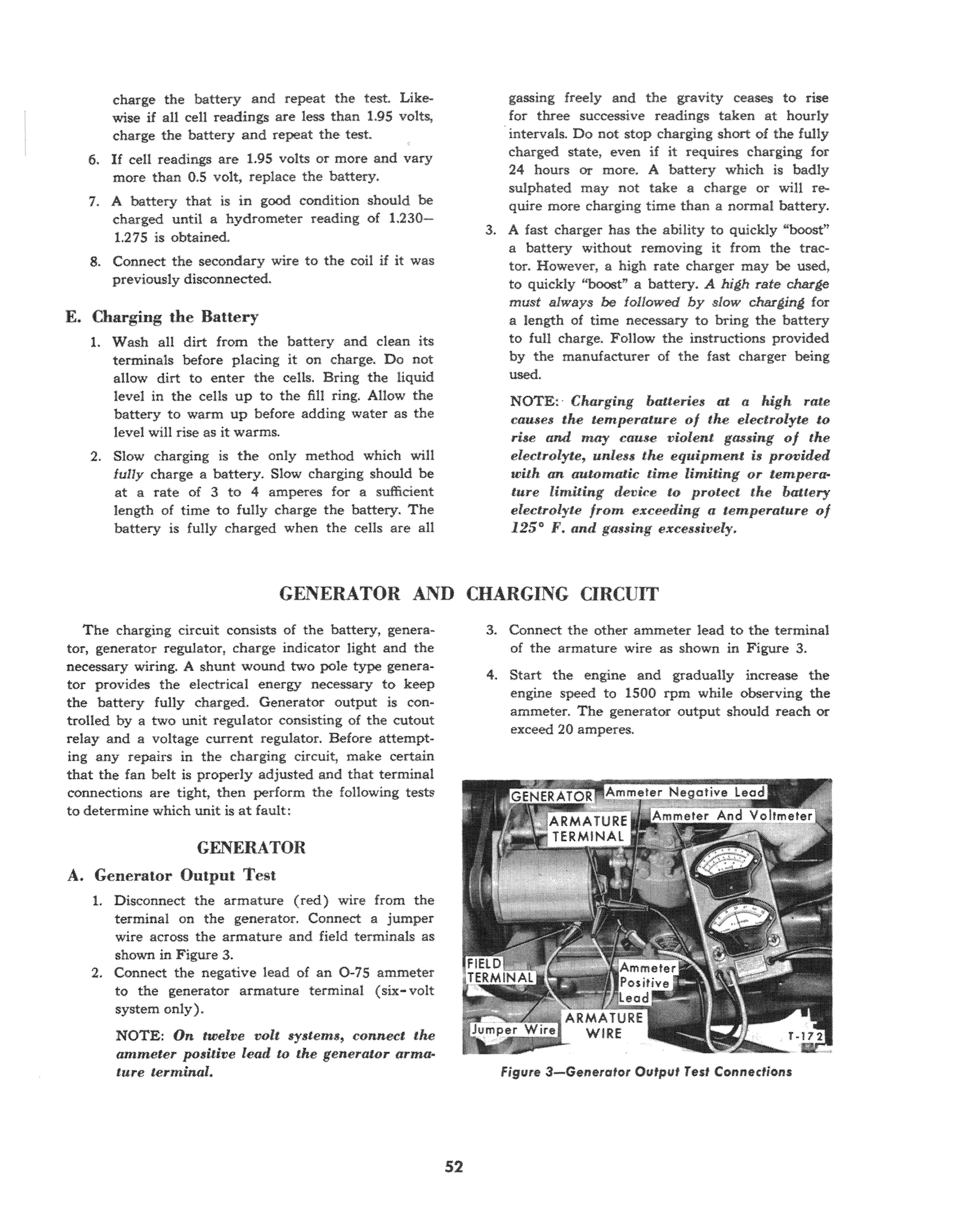
The charging circuit consists of the battery, generator, generator regulator, charge indicator light and the necessary wiring. A shunt wound two pole type generator provides the electrical energy necessary to keep the battery fully charged. Generator output is controlled by a two unit regulator consisting of the cutout relay and a voltage current regulator. Before attempting any repairs in the charging circuit, make certain that the fan belt is properly adjusted and that terminal connections are tight, then perform the following tests to determine which unit is at fault: 3. Connect the other ammeter lead to the terminal of the armature wire as shown in Figure 3.
4. Start the engine and gradually increase the engine speed to 1500 rpm while observing the ammeter. The generator output should reach or exceed 20 amperes.
GENERATOR A. Generator Output Test
1. Disconnect the armature (red) wire from the terminal on the generator. Connect a jumper wire across the armature and field terminals as shown in Figure 3. 2. Connect the negative lead of an 0 -75 ammeter to the generator armature terminal (six-volt system only).
NOTE: On twelve volt systems, connect the ammeter positive lead to the generator armatitre terminal.
Figure 3- Generator OUfput Test Connections
NOTE; Stop the engine and disconnect the jumper wire from the field and armature terminals as SOOlt as the generator output is obtained to prevent overheating tlte generator. 5. If the generator output is below 20 amperes or is erratic, check the generator belt tension and adjust if necessary. Repeat the test. If adjusting the belt does not increase the generator output to 20 amperes, remove and repair or. replace the generator.
B. Voltage Limiter and Cutout Tests
1. Prior to checking the generator regulator, the following three components of the electrical system must be checked, and their condition known. The wiring harness must be inspected and all connections checked for cleanliness and tightness. Corroded or dirty terminals cause high resistance which hampers the performance of the system. Bare wiring must be replaced or repaired. The generator output test must be made to be sure it is working satisfactorily and the battery specific gravity must be checked to determine its state of charge. If specific gravity is below 1.250, the battery must be charged or replaced with a fully charged battery. 2. With the ammeter wires still connected as in the generator output test, (with the exception of the jumper wire) connect the voltmeter negative lead to the ammeter positive lead.
NOTE: If working on a twelve-volt system, connect the voltmeter positive lead to the ammeter negatit)e lead.
Connect the other voltmeter lead to ground as shown in Figure 4, 3. Start the engine and allow it to idle until the regulator reaches norma! operating temperature (obtained after a 30 minute run at a 4.5 to 5.0 amp charge rate). Slowly increase the engine speed to 1500-2000 rpm while observing the ammeter and voltmeter. Cutout closing will be indicated by a "flick" of the voltmeter pointer and a rise of the ammeter pointer. The voltage at the time the voltmeter pointer "flicks" or momentarily drops back, will be the cutout dosing voltage. The cutout dosing voltage should be 6.0-6.6 volts for a six-volt system with the regulator at SO°F., or 12.2-13.0 for a twelvevolt system under the same temperature conditions. This test may have to be repeated several times to note the flicking of the voltmeter pointer.
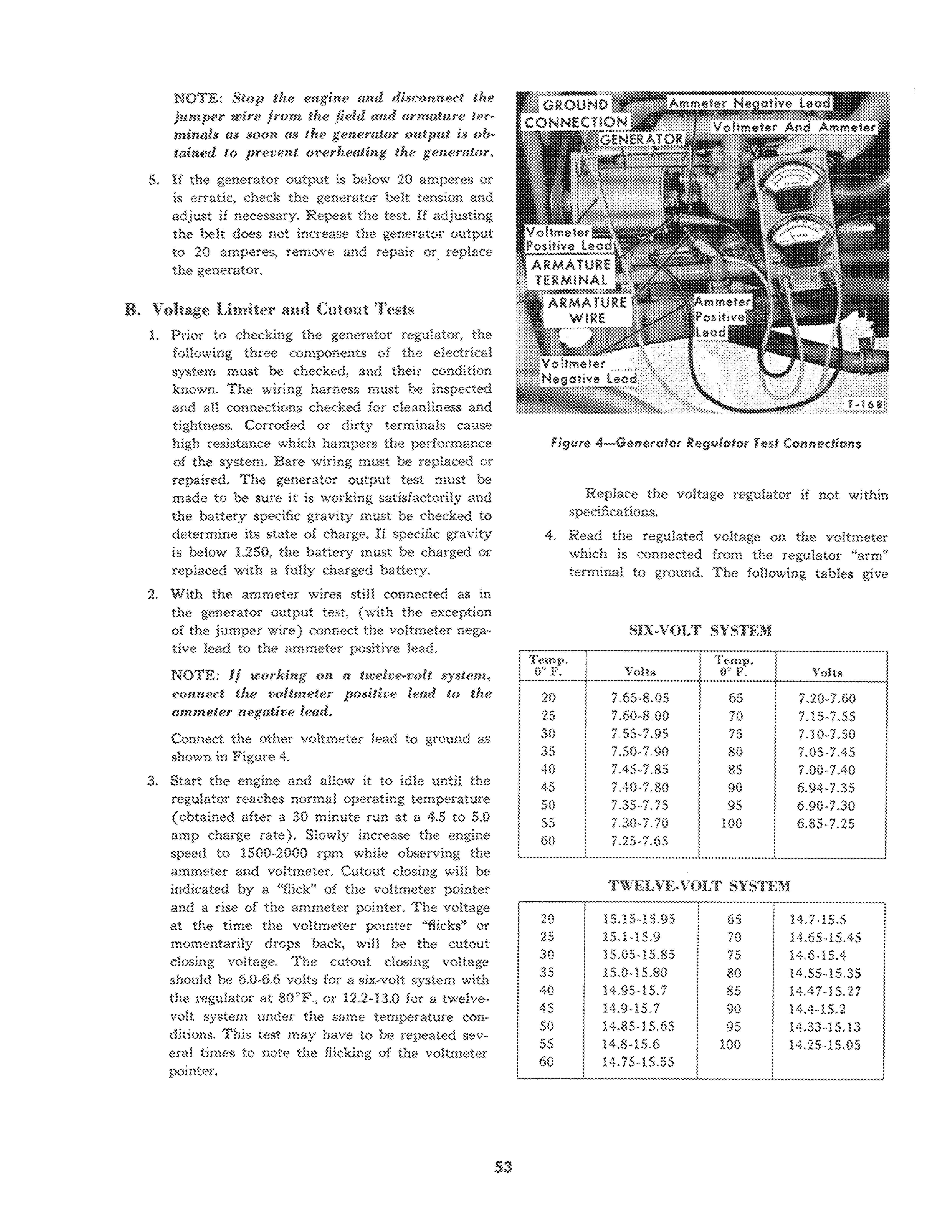
Figure 4-Gcl'lerafQf ReglJlotor Test COl'll'lectiol'l$
Replace the voltage regulator if not within specifications. 4. Read the regulated voltage on the voltmeter which is connected from the regulator "arm" terminal to ground. The following tables give
SIX-VOLT SYSTEM
O· v ' . I Volts
Temp.
Volts
20 7.65·8.05 65 7.20-7.60 25 7.60·8.00 70 7.15-7.55 30 7.55-7.95 75 7.10-7.50 35 7.50-7.90 80 7.05-7.45 40 7.45-7.85 85 7.00·7.40 45 7.40-7.80 90 6.94-7.35 50 7.35·7.75 95 6.90-7.30 55 7.30-7.70 100 6.85-7.25 60 7.25·7.65
TWELVE.VOLT SYSTEM
20 15.15-15.95 65 14.7-15.5 25 15.1-15.9 70 14.65-15.45 30 15.05-15.85 75 14.6-15.4 35 15.0-15.80 80 14.55-15.35 40 14.95-15.7 85 14.47-15.27 45 14.9-15.7 90 14.4-15.2 50 14.85-15.65 95 14.33-15.13 55 14.8-15.6 100 14.25-15.05 60 14.75-15.55
8
o 5 10 CURRENT
15
Figure 5-Six-Vc" Regulator Test Curve 20
T-18 4
the proper setting of the voltage limiter for various temperatures when tested with a current of 4.5 to 5.5 amperes. 5. Disconnect the test leads and connect the armature wire to the armature terminal on the generator.

C. Generator Removal and Installati.on
1. Disconnect the armature, field and ground wires at the generator terminals. 2. Remove the adjustment arm to generator bolt, the generator belt, and the two pivot bolts from the mounting bracket. Then remove the generator.
3. Clean the mating surfaces of the generator and mounting bracket. Instan the generator in the bracket with two pivot bolts and lockwashers.
Install the generator belt, and the adjustment arm-to-generator bolt. 4. Adjust the belt tension and tighten all bolts securely, Install the armature, field, and ground leads on their respective terminals.
5 10 15 20 25 30 CURRENT r·1 $ S Figure 6-Twelve-Volt Regulator Test Curve
D. Generator Disassembly
1. Remove the through bolts, the rear end plate and the armature frame, Figure 7. When separating the generator, take care not to lose the dowel pins. 2. Clamp the armature in a vise equipped with soft metal jaws and remove the pulley retaining nut and lockwasher.
3. Use a suitable puller to remove the pulley, then pry the woodruff key out of the shaft and remove the front end plate.
IMPORTANT: Always make an electrical test oJ brushes and brrlsh holders and field coils
Jor possible shorting before disassembly, Also check the Jront bearing and rear bearing or ball bearing for signs of wear or dejects before removing them.
4. Remove both brushes by removing the attaching screws. Remove the brush terminal screw, insulator, and brushes.
5. Remove the snap ring from the front end plate and remove the front bearing.
FRONT END PLATE NUT
FLATW OUTER
INNER INSULATOR LOCATING DOWEL
BEARING
GROUND BRUSH TERMINAL SPRING
\ ,REAR INSULATOR
FlATWASHER
\ /-NUT
PLATE \ BRUSH
PLUG BOLT
FIELD TERMINAL WICK lOCKWASHER
RING
LOCATING DOWEL
LOCK WASHER FIELD COilS
Fig. 7-Generator Disassembled
REAR END PLATE TERMINAL
T -176
E. Generator Inspection-Visual
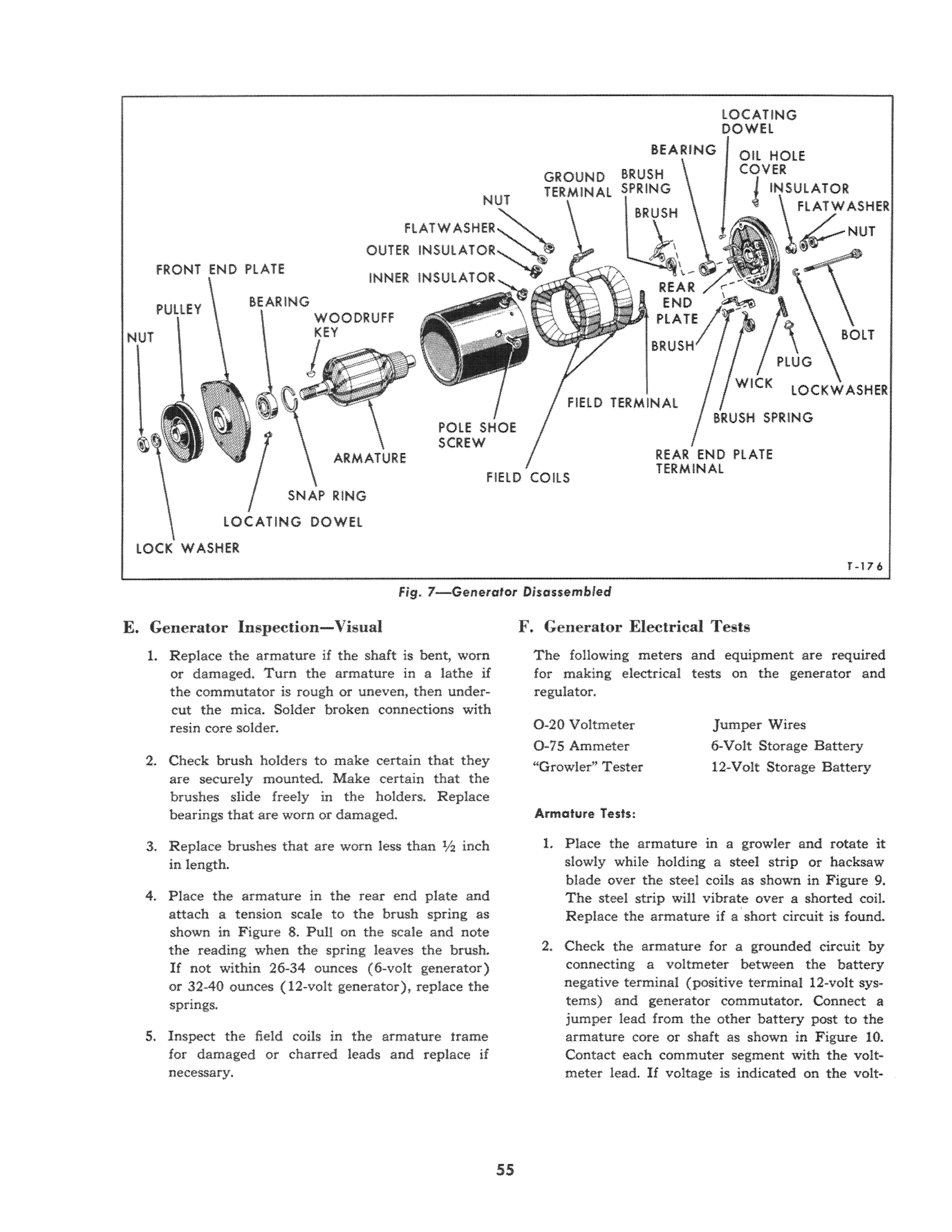
1. Replace the armature if the shaft is bent, worn or damaged. Turn the armature in a lathe if the commutator is rough or uneven, then undercut the mica. Solder broken connections with resin core solder.
2. Check brush holders to make certain that they are securely mounted. Make certain that the brushes slide freely in the holders. Replace bearings that are worn or damaged.
3. Replace brushes that are worn less than lI2 inch in length.
4. Place the armature in the rear end plate and attach a tension scale to the brush spring as shown in Figure 8. Pull on the scale and note the reading when the spring leaves the brush.
If not within 26-34 ounces (6-volt generator) or 32-40 ounces (12-volt generator), replace the springs.
5. Inspect the field coils in the armature trame for damaged or charred leads and replace if necessary. F. Generator Electrical Tests
The following meters for making electrical regulator. and equipment are required tests on the generator and
0-20 Voltmeter 0-75 Ammeter "Growler" Tester Jumper Wires Storage J3attery 12-Volt Storage Battery
Armature Tests:
1. Place the armature in a growler and rotate it slowly while holding a steel strip or hacksaw blade over the steel coils as shown in Figure 9. The steel strip win vibrate over a shorted coil. Replace the armature if a short circuit is found.
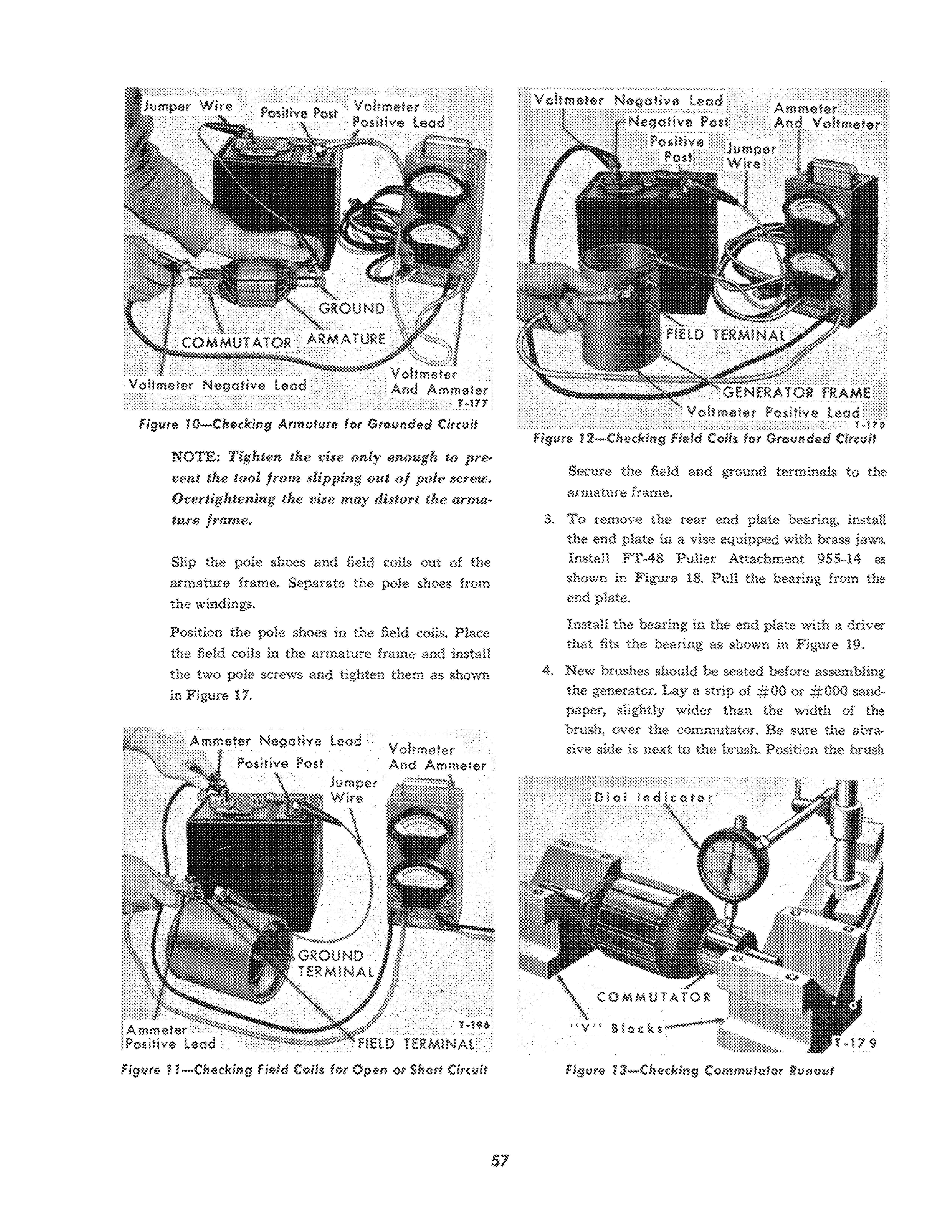
2. Check the armature for a grounded circuit by connecting a voltmeter between the battery negative terminal (positive terminal 12-volt systems) and generator commutator. Connect a jumper lead from the other battery post to the armature core or shaft as shown in Figure 10. Contact each commuter segment with the voltmeter lead. If voltage is indicated on the volt-
Breaker Point Tens ion Scale-12151
T -173
Figure 8-Checking Srush Spring Tension
Generator Field Coil Tests.

1. Check the field coils for an open circuit by attaching an ammeter between the generator field terminal and the battery negative post (positive post on 12-volt systems).
NOTE: Use the proper voltage battery lchen making electrical tests.
2. Connect another lead from the other battery post to the generator ground terminal as shown in Figure 11. The ammeter should register 1 V2-2 amperes. A higher current reading indicates a short circuit If no current flows, the field has high resistance or an open circuit.
3. Check for a grounded circuit by connecting a jumper wire from the generator case to the battery positive post (negative post on 12-volt systems). Connect a voltmeter between the generator field terminal and the other battery post as shown in Figure 12. If a reading is indicated on the meter, the field coils are grounded and must be replaced G. Generat.or Repair
1. Check the commutator ronout as shown in
Figure 13. If the commutator surface is rough or more than 0.002 inch out of round, it should be turned in a lathe Or with a turning tool as shown in Figure 14.
Remove no more copper than necessary to clean up the commutator.
After the commutator is turned down, undercut the mica between the bars '%2 inch below the copper, using the undercutting tool as shown in Figure 15. Figure 16 illustrates samples of proper and improper undercutting. Polish the commutator with :# 00 to # 000 sandpaper to remove aU burrs. Brush away aU particles of copper and mica insulation between the commutator segments. Recheck the armature in a growler.
2. To remove the field coils, remove the field and ground terminal screws from the armature frame. Remove the two pole screws as shown in Figure 17. The tool can be fabricated by electric welding a piece of % 6 inch square bar stock in a nut.
Figure 9-Ched<ing Armature for Shott Circuits Using a "Growler" Tester
Figure lO-Checking Armature for GrolJnded Circuit
NOTE; Tighten the vise only enough to prevent the tool from slip ping out of pole screw. Overtightening the !'ise may distort tile arma·
lll,re frame.
Slip the pole shoes and field coils out of the armature frame. Separate the pole shoes from the windings.
Position the pole shoes in the field coils. Place the field coils in the armature frame and install the two pole screws and tighten them as shown in Figure 17. Secure the field and ground terminals to the armature frame.
3. To remove the rear end plate bearing, install the end plate in a vise equipped with brass jaws.
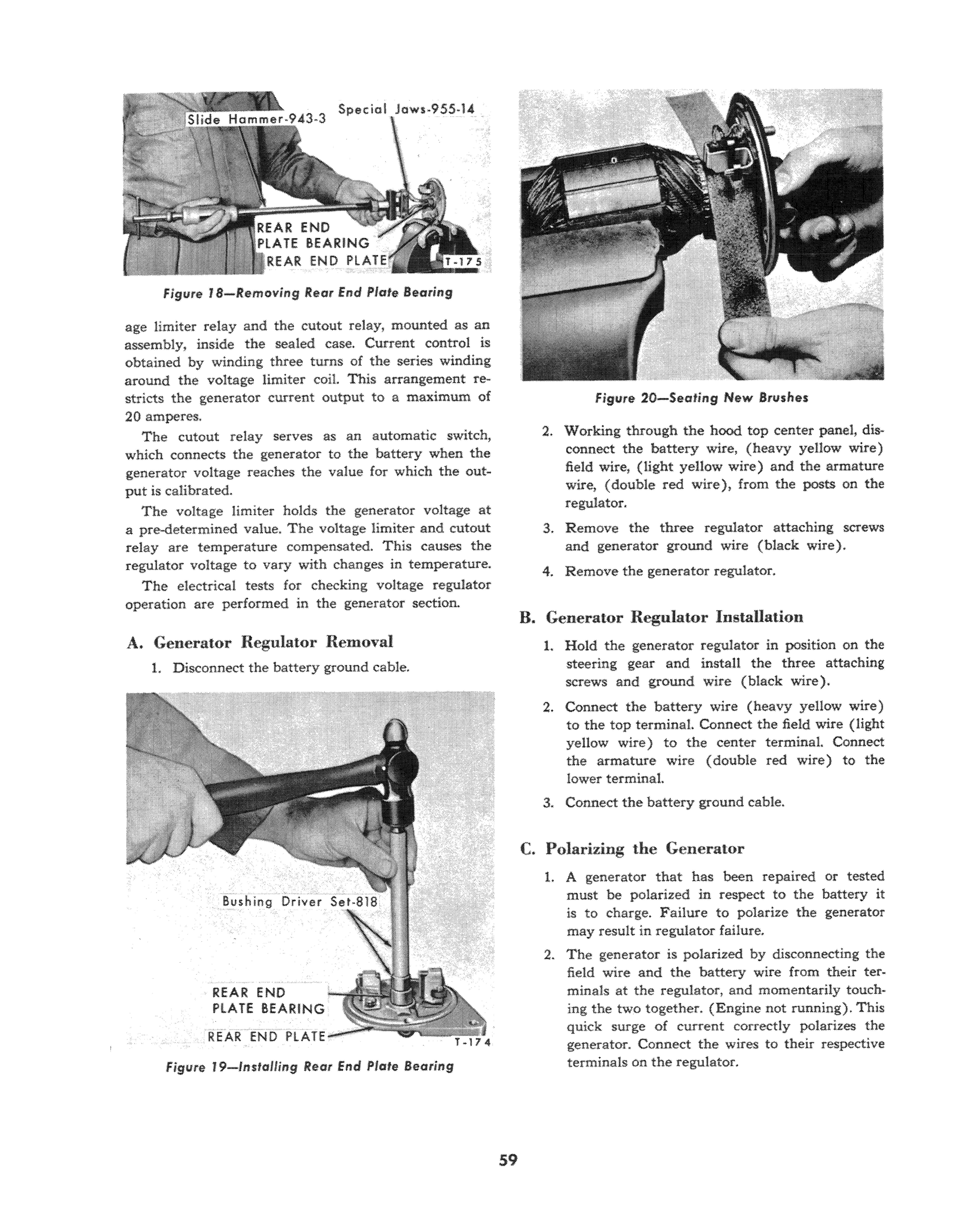
Install FT-48 Puller Attachment 955-14 as shown in Figure 18. Pull the bearing from the end plate.
Install the bearing in the end piate with a driver that fits the bearing as shown in Figure 19. 4. New brushes should be seated before assembling the generator. Lay a strip of #00 or #000 sandpaper, slightly wider than the width of the brush, over the commutator. Be sure the abrasive side is next to the brush. Position the brush
Figure 1 J -Checking Field Coils lor Open or Short Circuit
Figure 13-Checking Commutator RlJnout
CUT ONLY ENOUGH STOCI< TO CLEAN UP COMMUTATOR
Figure 14- hming Armature Commutator
springs on the brushes, then pull the sandpaper from under the brush, Figure 20, until the brush conforms to the armature. After brushes are seated, blow the abrasive dust from the mutator with moisture free air.
H. Genera.tor Assembly
1. Install the armature brush in the brush holder.
Push the insulator through the hole from the external side of the end plate. Place the brush lead on the armature terminaL Secure the semhly by installing the flat washer and nut,
Figure 7. Connect the other brush to the end plate with a screw and lockwasher. 2. Install the end plate assembly on the armature being careful not to chip the brushes.

Figure i 6-Examples of Proper and Improper Undercutting
3. Slip the armature into the rear of the armature frame and align the dowel in the rear end plate with the notch in the frame.
4. Carefully press the bearing into the front end plate and install the lock ring. Slip the front end plate onto the armature and align the dowel in the end plate with the notch in the frame. 5. Install the two generator through bolts. 6. Tap the woodruff key into the armature shaft and install the pulley. Secure the puIIey with a nut and lockwasher.
GENERATOR REGULATOR
The generator regulator used on an series tractors, consists of two main control units. Namely, the volt-
Figure IS-Undercutting Mica from Commufator figure 17-Removing Pole Screw
Figure lS-Removing Rear End .Piafe Bearing
age limiter relay and the cutout relay, mounted as an assembly, inside the sealed case. Current control is obtained by winding three turns of the series winding around the voltage limiter call This arrangement restricts the generator current output to a maximum of 20 amperes.
The cutout relay serves as an automatic switch, which connects the generator to the battery when the generator voltage reaches the value for which the output is calibrated.
The voltage limiter holds the generator voltage at a pre-determined value. The voltage limiter and cutout relay are temperature compensated. This causes the regulator voltage to vary \vith changes in temperature.
The electrical tests for checking voltage regulator operation are performed in the generator section.
A. Generator Regulator Relnoval
L Disconnect the battery ground cable.
REAR END PtA TE REARING
PLATE
figure f 9-1nstalling Rear End Plate Bearing
Figure 20-Seating New Brushes
2. Working through the hood top center panel, disconnect the battery wire, (heavy yellow wire) field wire, (light yellow wire) and the armature wire, (double red wire), from the posts on the regulator. 3. Remove the three regulator attaching screws and generator ground wire (black wire). 4. Remove the generator regulator.
B. Generator Regulator Installation
1. Hold the generator regulator in position on the steering gear and install the three attaching screws and ground wire (black wire). 2. Connect the battery wire (heavy yellow wire) to the top terminaL Connect the field wire (light yellow wire) to the center terminal. Connect the armature wire (double red wire) to the lower terminal. 3. Connect the battery ground cable.
C. Polarizing the Generator
1. A generator that has been repaired or tested must be polarized in respect to the battery it is to charge. Failure to polarize the generator may result in regulator failure. 2. The generator is polarized by disconnecting the field wire and the battery wire from their ter· minals at the regulator, and momentarily touching the two together. (Engine not running). This quick surge of current correctly polarizes the generator. Connect the wires to their respective terminals on the regulator.


