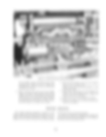
Figure 21-1ntake and Exhaust Manifold Installed
on the cylinder head and install the four bolts, one stud, fiat washers and nuts. Tighten the attaching bolts and nuts evenly and alternately to 40-50 ft. lbs, torque. 4. Place a clamp on the outlet end of the muffler. Instan the muffler outlet support elbow in the muffler with the two mounting bolts in alignment with the hole in the fuel tank support bracket and cylinder head. Install the two elbow attaching bolts, tighten the muffler front damp.
5. Secure the heat shield to the fuel tank supports with the four attaching bolts. NOTE: The nut, bolt and lockwasher is used in the u.pper hale. 6. Position the outlet pipe, rain cap assembly and clamp on the outlet support elbow. Tighten the clamp to secure the outlet pipe. 7. Connect the wire to the manifold rear heater. 8. Install a new gasket on the intake manifold, then install the air cleaner.
TROUBLE SHOOTING The trouble shooting procedures contained in this section pertain only to the diesel fuel system and component parts. The diesel fuel system consists of the aif cleaner, the fuel tank, fuel filter, fuel injection pump,
113
fuel injectors and the connecting fuel lines. It cannot be stressed too strongly for keeping the diesel fuel system free of dirt. Most all of the troubles in the system can be contributed to dirt.


