SERV1851 02/08
- 184 -
Text Reference Swing System Swing Motor
SWING SYSTEM
Anti-reaction Valves
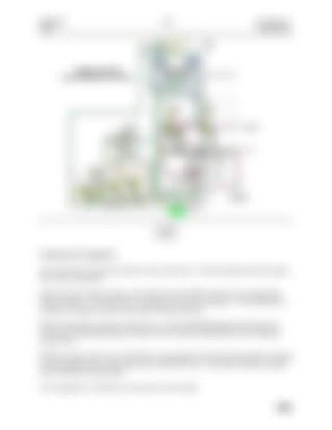
SWING COMPONENTS - NEUTRAL
Swing Valve
Stick 1 Valve
From Idler Pump
To Tank
Swing/Stick Pilot Valve
Swing Brake Solenoid
To Stick Regen Valve To Boom 2 Valve Swing Priority Valve
From Pilot Pump
From Straight Travel Valve
Slow Return Check Valve
Pilot Manifold
142
Swing System Components The swing circuit controls the rotation of the swing motor. The idler pump provides the pump flow to the swing motor. When either one of the joysticks is moved from the NEUTRAL position, the swing parking brake is released. The swing motor is mounted on top of the swing drive. The swing drive is installed on the upper structure and rotates the upper structure. When the hydraulic activation control lever is in the UNLOCKED position, pilot pump oil flows to the swing parking brake solenoid valve in the pilot manifold and to the swing pilot control valve. With the swing control valve in NEUTRAL, pump supply oil from the idler pump flows though the center bypass valve swing control valve to the NFC valve. The return oil creates a signal used to destroke the idler pump. The swing brake is currently on so the motor will not rotate.


