5 minute read
Pilot Controls and Valves


7 5 3
1
2 4
6 8
9 10
69
Pilot Controls and Valves
Pilot controls in the cab include:
- left (1) and right (2) travel pedals
- left (3)and right (4)travel levers
- hydraulic hammer pedal (5) (optional)
- straight travel pedal (6) (optional)
- left joystick (7)to control the swing and stick (SAE HEX pattern)
- right joystick (8) to control the bucket and boom (SAE HEX pattern)
- foot rest (9 and 10)
70
When the pilot joystick lever is shifted, the joystick contacts the rod and pushes it down against its spring. The rod will contact the spool and move it down against its spring. Depending on how far the lever is shifted, determines how far the spool moves.
As the spool moves down, the spool will close off the drain passage for the oil to the control valve and meter pilot oil to the control valve to cause the control spool (not shown) to shift. The greater the pilot oil flow to the control spool the greater the control spool travel.
As pressure increases in the pilot line to the control valve, the pressure works on the spool to move the spool up to a balance position against the spool and plunger springs to maintain the pilot pressure in the pilot line. This action will maintain the position of the control spool in the control valve until the joystick is moved.
In summary, once the pilot lever is shifted, the pilot valve becomes a pressure reducing valve which maintains a downstream pressure equal to the spring forces above the spool.
When the joystick is released, the joystick will return to the NEUTRALposition due to the force of the spring moving the spool back up. When this occurs, the pilot oil is blocked by the spool from flowing to the control valves to shift the spool and pilot oil at the control spool is drained to the tank past the spool.
71
The travel pilot control valve operates similar to the implement pilot valves.
Depending on how far the the travel pedal or lever is moved, will determine the amount of pilot oil directed to the respective travel control valve.
Adampening function is built into the travel pilot control valve which allows the operational speed of the travel lever/pedal to correspond to the movement of the operator's foot. The dampening function also prevents the vibration that occurs when the travel lever/pedal is released.
When travel lever/pedal is moved suddenly from the NEUTRALposition, the rod is pushed downward. The rod moves the dampening piston downward. The hydraulic oil below the dampening piston is pressurized. An orifice check valve allows the trapped hydraulic oil below the dampening piston to gradually flow into into the metering spring chamber, which is open to the tank. The gradual flow of oil through the orifice check valve provides the the dampening function.
72
The attachment circuits are controlled by proportional solenoid valves. The valves receive PWM signals from the Work Tool and Machine ECM to energize the solenoid. Depending on the amount of current sent will determine how far the solenoid shifts the spool.
Pilot oil is directed to and from the attachment circuits to control the position of the control spool for the attachment.
73
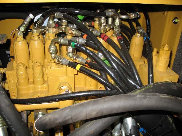
When the joysticks are operated, the pilot control valves send pilot pump oil through the pilot lines to pilot ports (arrows) at the main control valve group to shift the spools in the main control valve.
Additional pilot lines are located below the main control valve to shift the control spools in the opposite direction.
74
Pilot oil enters a control valve from either end to shift the main control spool.
The control spool will shift in proportion to the amount of pilot oil sent to the control spool from the a pilot valve or solenoid.
For some circuits proportional solenoid valves are used to direct pilot oil to shift the control spool.
75
The pilot logic network is a series of open-center flow passages through the hydraulic control valves. These passages are internal to the main control valve group. Pilot oil flows through the logic circuit. The open-center flow passages are open to the tank when all valves are in NEUTRAL.
When one or more of the implement control valves are activated, the open-center passage is blocked preventing oil flow to the tank.
76
If one or both of the travel valves are moved, then oil is blocked from flowing through the pilot logic network to the tank. Pressure builds upstream of the shifted valve(s), closes the travel pressure switch, and sends a signal to the main relief valve.
When the travel pressure switch is closed, a signal is sent to the Machine ECM to activate the travel alarm and resume the set dial speed if Automatic Engine Speed Control (AEC) or one-touch low idle was active.
The signal to the main relief, raises the operating pressure of the hydraulic system. This allows for higher pressures to be delivered to the travel motors, increasing drawbar pull.
77
If an implement valve is shifted, the implement pressure switch closes and a signal is sent to the Machine ECM. The Machine ECM activates the swing parking brake solenoid to release the swing parking brake. The ECM will also resume the engine speed requested by the speed dial position if the AEC or the one-touch low idle was active.
For straight travel operation to occur both travel valves and an implement valve must be shifted. This causes all of the events that occur when either an implement or a travel valve is shifted.
In addition, this sends a signal to the straight travel valve. The straight travel valve then shifts and allows one pump to be dedicated to the driving of the travel motors to allow the machine to track straight if an implement function is activated while traveling. Excess flow available from the implement functions is also now available for travel functions.