3 minute read
Pilot Manifold


5
2
1
3
4
63
Pilot Manifold
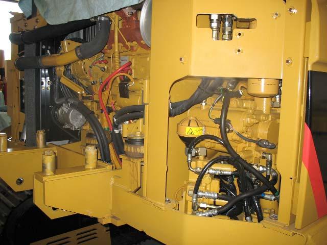
The pilot manifold is the same as the "C" pilot manifold. The pilot manifold is located next to the main control valve group.
The hydraulic activation valve (1) and solenoid (2) are located in the pilot manifold along with the swing brake solenoid (3) and the two-speed travel solenoid (4).
The accumulator (5) will provide pilot pressure oil to the pilot system when the pilot pump flow is inadequate.
Insufficient pilot oil flow to the pilot system may be caused by the following two reasons:
-Implements are lowered while the engine is stopped and oil supply to the main control valves is stopped. -Combined implement/swing/travel operations.
64
Oil from the pilot pump enters the pilot manifold to be distributed to the various components of the machine. Some of the pilot oil flow is directed to the swing priority valve, and to the two speed travel solenoid valve. The rest of the pilot oil flows through the check valve.
Two Speed Solenoid Valve: The two speed solenoid valve directs oil flow to the displacement change valve in the travel motor. In the illustration above, the solenoid is energized. Pilot oil is directed to the travel motors to shift the displacement change valves (not shown). When the displacement change valves shift, the motors will destroke for higher speed.
Check Valve: The pilot manifold also contains a check valve. The check valve maintains pilot accumulator pressure in the pilot circuit when the engine is not running.
Pilot Accumulator: The pilot accumulator is used to release the swing brake and for lowering the boom and stick in the event of a loss of pilot system pressure or a dead engine. The pilot accumulator also helps to dampen pressure spikes in the pilot system, which enhances the stability of the machine control systems.
The accumulator stores pilot pressure oil for use at the main control valves. During some operations, the pilot system needs more oil because there is insufficient flow from the pilot pump.
Implement Hydraulic Lockout Solenoid Valve and Hydraulic Activation Valve: These two valves work together to either prevent the implement control valves and the motors from being activated or to allow them to be activated. In the de-energized position, no pilot oil is available to operate the implements. Pilot oil is blocked at both valves.
When the hydraulic lockout control lever in the cab is in or moved to the LOCKED position, the limit switch plunger is not depressed by the control lever. The limit switch is in the OFF state.
When the hydraulic activation control lever is in the LOCKED position, the hydraulic activation solenoid is not energized.
The spool is held up by a spring. The spool blocks the pilot supply oil from going to the pilot valves. The spool also opens a passage to drain from the pilot valves to the tank.
In the locked position, if the joysticks are moved the cylinders and the motors cannot be activated.
Swing Brake Solenoid Valve: The swing brake solenoid valve energizes to release the spring-applied, hydraulically-released wet disc swing brake. The swing brake is automatically released when any implement joystick function is performed by the operator. With the swing brake solenoid valve de-energized the swing brake is engaged by springs.
65
When the hydraulic lockout control lever in the cab is placed in the UNLOCKED position, the limit switch closes the circuit path and the lockout solenoid valve is energized.
When the implement hydraulic lockout solenoid valve is energized, pilot oil is directed to move the hydraulic activation valve down. Pilot oil flows through the hydraulic activation valve to the swing brake solenoid valve, the left and right joysticks, and the travel pilot valves.
When a implement is activated the swing brake solenoid is energized by the Machine ECM. Pilot oil is directed through the swing brake solenoid valve to release the swing park brake in the swing motor group.