4 minute read
C4.2 ACERT™ ENGINE


38
C4.2 ACERT™ ENGINE
The 311D/312D/314D Excavators are equipped with a C4.2 ACERT™ Engine. The C4.2 engine is a 4.2 liter engine that uses a common rail fuel system.
The common rail fuel system includes an electronically controlled high pressure fuel injection pump, a fuel manifold, and electronically controlled injectors.
The A4:E2 Engine ECM controls the pump solenoid, which controls the injection pump fuel flow through high pressure lines to the fuel injectors. The Engine ECM also controls the on/off fuel injector solenoids.
The C4.2 ACERT™ engines meet U.S. Environmental Protection Agency (EPA) Tier III Emissions Regulations for the North America market and Stage IIIa European Emissions Regulations.
NOTE: This presentation provides an overview of the common rail fuel system and covers 311D/312D/314D Excavators engine component locations. For detailed information on the C4.2 ACERT™ Engine, refer to Service Training Meeting Guide "C4.2/C6.4 and C4.4/C6.6 ACERT™ Engines with Common Rail Fuel System--Machine Applications" (SERV1837).
Basic machine specifications for the C4.2 engine are:
- Configuration: Four cylinders inline, 16-valve crossflow cylinder head
- Fuel System: Direct injection, common rail
- Aspiration: Turbo-ATAAC
- ECM: A4:E2
- Rated power: 91 - 98 kW(122 - 131 hp) @ 1700 - 2200 rpm
- Displacement: 4.2 liter (256 in3)
- Bore: 102 mm (4.02 in.)
- Stroke: 130 mm (5.12 in.)
- Compression ratio: 16.5:1
39
Some of the C4.2 ACERT™ engine features are:
-The high pressure fuel pump is controlled by the Engine ECM and provides high pressure fuel to the injectors.
-The electronically controlled injectors are controlled by the Engine ECM to inject high pressure fuel into the combustion chamber.
- The cylinder head includes 4 valves per cylinder.
-The engine block includes a scalloped crank case with extra ribbing, which provides a more ridged structure with a lower noise attenuation (sound absorption).
-The aluminum pistons have improved oil control.
-The A4:E2 Engine ECM controls fuel pressure, speed governing, air/fuel ratio, engine start/stop strategy, and provides diagnostics.
-The common rail fuel system allows tight control of injection events and optimizes engine performance across all load and speed ranges. The common rail system reduces combustion noise, and NOx and PM emissions.
40
Contamination control is critical with the common rail fuel system. Very high pressures require close tolerances in the fuel injection pump and injectors. It is important that technicians pay close attention to cleanliness and contamination control during even the most routine maintenance.
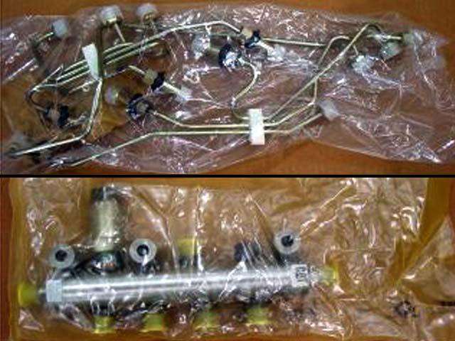
Keep components in their original packaging until ready to install and inspect packaging to ensure components are still sealed and free of dirt or damage.
High pressure fuel lines are single use items and must be replaced after unseating any fittings. The common rail fittings/ports and the injector fittings/ports must be capped immediately after unseating. Do not remove the caps from new components until just before the fittings are tightened.
New pipes must be handled carefully and not bent in any way. If a sealing cap is not on each end of the pipe when a new pipe is removed from the packaging, it must not be used.
Do not use compressed air or solvent to clean any fuel system components.
All fittings must be torqued to the correct specification. If a leak occurs, replace the pipe with new pipe. The rubber boots that seal the valve cover opening are also single use parts.
Similarly, any retaining clips that are removed should be replaced with new clips to ensure they fasten properly. During reassembly, be sure the clips are placed in the proper locations to prevent vibration and potential leaks from occurring.
Fuel pressures between the injection pump and fuel injectors can reach 160 MPa (23,200 psi), so specific safety procedures must be carefully followed.
WARNING
Neverloosen oropen a high pressure fuel line while cranking orrunning a Common Rail fuel system engine. Common Rail fuel systems operate at extremely high pressures often in excess of 160 MPa (23,200 psi). Extreme care should also be taken before disassembly of any high pressure fuel system components afteran engine shutdown. Referto the appropriate service information before performing any service on the high pressure fuel system components.
7
3 1
6 5 4 2

41
This illustration shows an overhead view of the C6.4 engine cylinder head with the rocker cover removed. The C4.2 components are the same.
The C4.2 is a four valve per cylinder engine with the valves arranged in an exhaust-intake manner from the front of the cylinder head to the rear. Exhaust valves are actuated by the short rocker arm (1) which presses down the exhaust valve bridge (2) and unseats the exhaust valve pair. Long intake rocker arms (3) are used to depress the intake valve bridge (4) and open the intake valves.
The electronic fuel injector (5) is centrally located between the intake and exhaust valve pairs for each cylinder. The Engine ECM will control the duration and timing of the fuel injector in relation to sensor inputs to achieve maximum fuel efficiency emissions compliance.
Alarge rubber boot (6) seals the opening in the valve cover base where the high pressure fuel injector supply line passes through the base and connects to the fuel injector.
The cylinder head features a "crossflow" design where the intake air enters the right side of the cylinder head and the exhaust gasses exit the left side through the exhaust manifold (7).