14 minute read
MAIN HYDRAULIC PUMPS AND CONTROLS


78
MAIN HYDRAULIC PUMPS AND CONTROLS
This section of the presentation will cover the main hydraulic pumps and pump controls for the 311D/312D/314D Hydraulic Excavators. The main hydraulic pumps are the same as the "C" series machines.
The main pump group consists of a variable displacement piston drive pump and an idler pump. The drive pump and the idler pump are contained in an integral housing. The drive pump and the idler pump are identical in construction and operation.
The pumps are sometimes referred to as S.B.S. (side by side)pumps
The main difference between all of the pumps is the maximum pump flow for each model.
Both the drive pump and the idler pump have individual pump control valves to control the pump flow.
79
Power shift pressure is controlled by the Machine ECM, and assists in pump regulation. Power shift pressure is one of three pressures to control the pump.
The pilot pump supplies the power shift PRVsolenoid with pilot oil. The Machine ECM monitors the selected engine speed (from the engine speed dial), the actual engine speed (from the engine speed sensor and Engine ECM), and the pump output pressures (from the output pressure sensors). The power shift PRVsolenoid regulates the pressure of the power shift oil depending upon the signal from the Machine ECM.
When the engine speed dial is in position 10, the Machine ECM varies the power shift pressure in relation to the actual speed of the engine.
The power shift pressure is set to specific fixed values dependent upon the position of the engine speed dial. The fixed power shift pressures assist cross sensing pressure with constant horsepower control.
When the engine speed dial is on position 10 and a hydraulic load is placed on the engine, this condition causes the engine speed to decrease below the engine's target rpm.
When this decrease occurs, the Machine ECM signals the power shift solenoid to send increased power shift pressure to the pump control valves. The increased power shift signal causes the pumps to destroke, and reduce the horsepower demand placed on the engine. With a decreased load from the hydraulic pumps the engine speed increases. This function is referred to as engine underspeed control.
Engine underspeed control prevents the engine from going into a "stall" condition where engine horsepower cannot meet the demands of the hydraulic pumps. The power shift signal to the pump control valves enables the machine to maintain a desired or target engine speed for maximum productivity.
Power shift pressure has the following effect on the main hydraulic pumps:
- As power shift pressure decreases, pump output increases. - As power shift pressure increases, pump output decreases.
Power shift pressure ensures that the pumps can use all of the available engine horsepower at all times without exceeding the output of the engine.
NOTE: The target rpm is the full load speed for a specific engine no load rpm. Engine target rpm is determined by the opening of one of the implement, swing, and/or travel pressure switches at the end of an operation. The Machine ECMthen waits 2.5 seconds and records the engine speed. This specific rpm is the "new" no load rpm.
The Machine ECMthen controls the power shift pressure to regulate pump flow to maintain the full load (target)rpm for the recorded no load rpm.
Target rpm can change each time the pressure switches open for more than 2.5 seconds.
80
The solenoid operated proportional reducing valve for the power shift pressure is located on the right/drive pump control valve. The proportional reducing valve receives supply oil from the pilot pump.
The solenoid receives a pulse width modulated signal (PWM signal) from the Machine ECM. The PWM signal sent from the Machine ECM causes the proportional reducing valve to regulate the pilot pressure to the pump control valves to a reduced pressure.
This reduced pressure is called power shift pressure (PS).
The output flow of the right/drive pump and the left/idler pump is controlled in accordance with the power shift pressure. The power shift pressure is used to control the maximum hydraulic pump output in relation to the engine rpm.
Adecrease in engine speed causes an increase in power shift pressure and a decrease in pump flow.
When the speed dial is at dial position 10, if the Machine ECM senses a decrease in engine speed below target rpm, the Machine ECM increases the PWM signal sent to the solenoid.
The magnetic force of the solenoid increases. As the magnetic force of the solenoid becomes greater than the force of the spring, the spool moves down against the force of the spring.
The downward movement of the spool blocks the flow of oil to the tank.
More power shift pressure oil is now directed to the pump control valve.
The increased power shift pressure acts on the drive pump control valve and the idler pump control valve.
If both pumps are upstroked, then both pumps will destroke as a result of the increase in power shift pressure. If only one pump is upstroked, only the upstroked pump will destroke.
81
If engine speed is above the target rpm, the Machine ECM decreases the power shift pressure to increase the pump flow.
When the Machine ECM senses an increase in engine speed above the target speed the Machine ECM decreases the PWM signal sent to the solenoid.
As the magnetic force of the solenoid becomes less than the force of the spring, the spool moves up.
The upward movement of the spool restricts the pilot oil flow to the power shift passage and opens the power shift passage to the drain. The power shift pressure is reduced.
The reduced power shift pressure acts on the drive pump control valve and the idler pump control valve.
Depending on which circuits are activated, the drive pump and/or the idler pump will upstroke as a result of an decrease in power shift pressure.
4
3
1 2 5
82
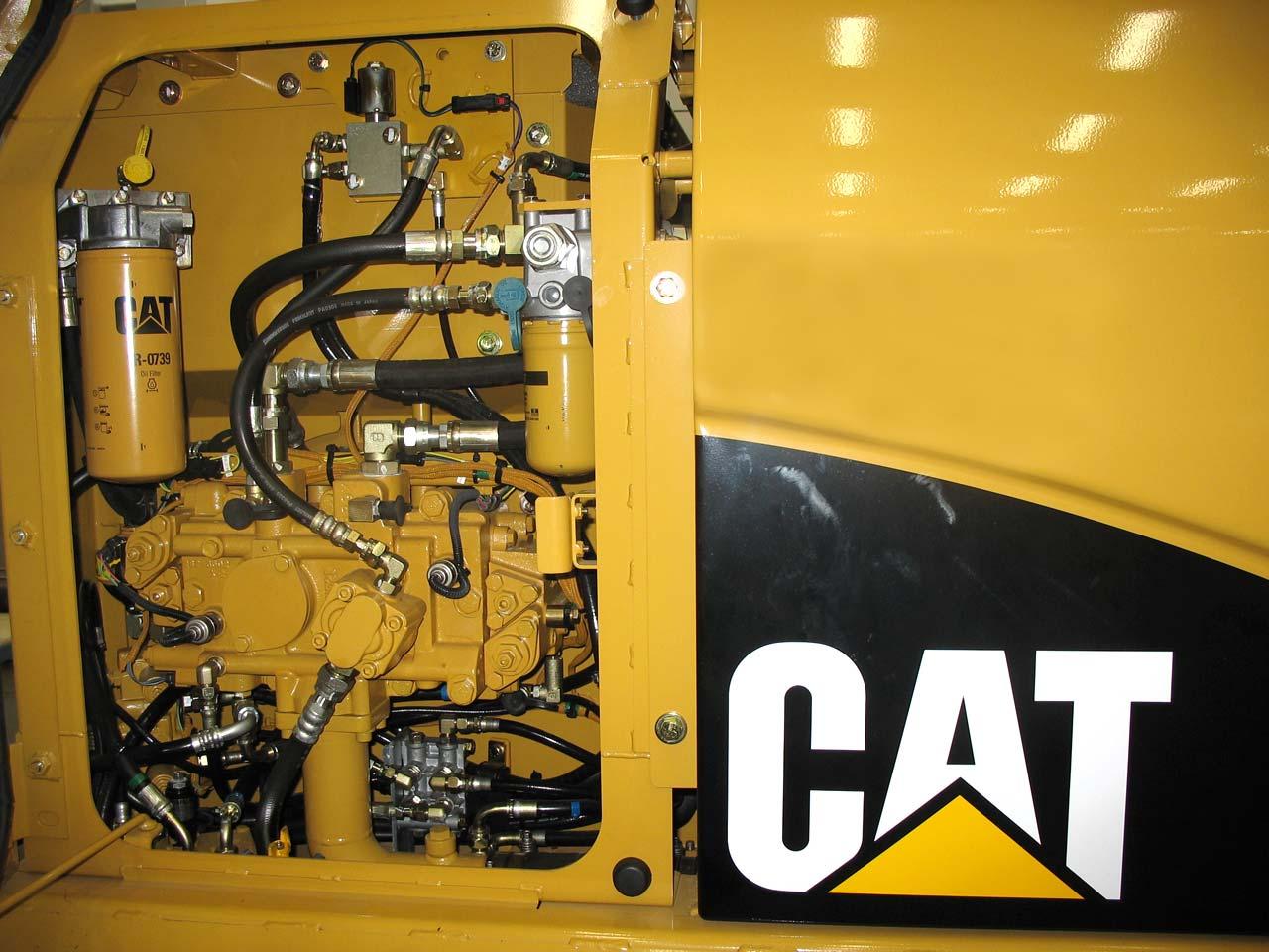
This illustration shows the main hydraulic pumps group. The drive pump (right pump) (1) is driven by the engine and the idler pump (left pump) (2) is driven by the drive pump. The pilot pump (3) is mounted on the idler pump. The optional medium pressure pump (not shown) is mounted to the drive pump.
The drive pump supplies oil to the right half of the main control valve group and the following valves:
- stick 2 control valve
- boom 1 control valve
- bucket control valve
- attachment control valve
- right travel control valve
The idler pump supplies oil to the left half of the main control valve group and the following valves:
- left travel control valve
- swing control valve
- stick 1 control valve
- boom 2 control valve
- auxiliary valve for tool control
The output of the variable-displacement piston pumps is controlled by the pump control valves (4 and 5) mounted to the ends of the main hydraulic pumps.
3 5
4 6

2
4
1 2
3
83
The power shift PRVsolenoid (1) provides a common power shift pressure for both pumps. The power shift PRVsolenoid is controlled by the Machine ECM.
The pump output pressure sensors (2) signal the Machine ECM of each pump's output pressure. The Machine ECM uses the pump output pressure, actual engine speed, and desired engine speed to determine the power shift pressure. The pressure sensors also signal the Machine ECM to cancel the AEC settings if the pump pressure increases above approximately 7370 kPa (1100 psi) and the engine rpm is still at an AEC setting.
The horsepower adjusting screws (3) adjust the hydraulic horsepower output of each pump. The maximum angle screw (4) limits the maximum flow of each pump.
The drive pump pressure tap (5) can be used to check the drive pump supply pressure. The idler pump pressure tap (6) can be used to check the idler pump supply pressure. Cat ETcan also be used to check these two pressures.
84
This illustration shows the pumps in STANDBYcondition.
The pump control valves will upstroke, destroke, or maintain the displacement of the pump depending on the conditions the pump control valve senses. The pump control valve controls oil pressure to the right side of the actuator, which controls the angle of the pump swashplate.
Each pump has a pump control valve which senses the three following control signals:
-a pump specific Negative Flow Control (NFC) signal from the main control valve group -a common power shift signal pressure generated by the power shift PRV -a common cross sensing signal pressure from the output of the two main pumps
NFC: NFC pressure is the most significant controlling signal in a negative flow controlled hydraulic system. Each pump control valve receives a specific NFC signal that is based upon the hydraulic demand for that specific pump.
Flow from the drive pump supplies the right half of the main control valve group, and has a corresponding NFCsignal for the drive pump. Flow from the idler pump supplies the left half of the main control valve group, and has a corresponding NFCsignal for the idler pump.
The open-center valves in the main control valve group allow pump output to flow through unrestricted. An orifice in the NFC valve creates a restriction to the pump output which increase the NFC pressure. The NFC pressure then signals the corresponding pump control valve. Each pump will remain at STANDBYas long as a full NFC signal pressure is present.
When a hydraulic control valve is shifted from the NEUTRALposition, the NFC signal pressure to the corresponding pump is reduced, which causes the pump to UPSTROKE. Any change in the movement of a valve in the main control valve group will effect the NFC signal because the valves send a variable NFC signal to the pump depending on the needed pump output.
Output of each pump is unaffected by a change in the NFC signal to the other pump. NFC pressure has the following effect on the main hydraulic pumps: - As NFC pressure decreases, pump output increases, - As NFC pressure increases, pump output decreases.
NFC signal pressure overrides all other control of the main hydraulic pumps.
Cross Sensing: Cross sensing pressure is essentially an average pressure from the output of the drive pump and the idler pump.
The output of each pump flows respectively to the left and right halves of the main control valve group. The output of each pump also flows to the cross sensing orifices. The pressure on the pump control valve side of the cross sensing orifices is an average of the output pressure of the two pumps, and is referred to as cross sensing pressure.
The cross sensing pressure compensates for the horsepower demand of each pump individually and for the two pumps together. With cross sensing assistance, the pumps constantly regulate to effectively use all of the available engine horsepower at any given time. This is referred to as constant horsepower control.
Cross sensing pressure has the following effect on the main hydraulic pumps: - As cross sensing pressure decreases, pump output increases, - As cross sensing pressure increases, pump output decreases.
Given a fixed NFCsignal and a fixed powershift pressure, cross sensing signal pressure regulates the output of the main hydraulic pumps.
NOTE: Hydraulic horsepower is a function of pump output flow and pressure. As pump flow or pressure increases, the horsepower demand increases. As pump flow or pressure decreases, the horsepower demand decreases.
85
The above illustration shows a cross sectional view of one of the main hydraulic pump control valves in STANDBY.
The main pumps will be in STANDBYcondition when the engine is running and all control valves are in the NEUTRALposition. Under these conditions the NFC pressure signal to the pump control valves is high. The pump can not upstroke until NFC signal pressure is reduced.
The high NFC signal pressure causes the NFC control piston to move left against the force of the NFC spring on the right. When the NFC control piston moves left it contacts the shoulder on the pilot piston, which causes the pilot piston to move the horsepower control spool against spring force.
The passage between horsepower control spool and the sleeve is now open to tank, causing the right end of the actuator to be open to the tank. The actuator moves to the right, moving the swashplate to a minimum angle, which causes pump output flow to be minimum.
NOTE: With the S.B.S. pumps, system pressure destrokes the pumps, while the signal pressure varies to upstroke the pumps.
86
The pumps must have a reduction in NFCpressure to upstroke from STANDBY. The illustration shows the pump control valves upstroking the pump due to a decrease in NFC signal pressure. As shown, there is no NFC signal pressure, indicating that at least one control valve has been fully shifted.
When the joysticks or travel levers are moved from the NEUTRALposition, NFC signal pressure decreases proportionally to the amount the joystick or travel levers are moved. When the NFC signal pressure decreases, the spring on the control piston forces the control piston to the right. The horsepower control springs on the left overcome the cross sensing signal pressure and the power shift signal pressure to move the horsepower control spool to the right.
With the horsepower control spool shifted to the right, the passages between the sleeve and the horsepower control spool are closed off to tank and pump output pressure is allowed to flow to the right side of the actuator. Because the right side of the actuator is larger than the left side, the greater force generated by the pressure on the right side causes the actuator to move left and upstroke the pump.
The pump can also be upstroked by a decrease in either power shift or cross sensing pressure, but only after a reduction in NFC pressure has occurred.
87
As the pump upstrokes, the movement of the actuator causes the control linkage to move the sleeve around the horsepower control spool. The sleeve moves to the right as the actuator moves to the left. Because of the geometry of the control linkage, a large movement of the actuator moves the sleeve a small amount (see Section D-D).
The small movement of the sleeve causes the passages between the sleeve and the horsepower control spool to open partially to tank and partially to the pump output. The pressure signal on the right side of the actuator is now metered, which causes the actuator to reach a balance point where the pump does not upstroke or destroke. With the actuator at a fixed position, the swashplate angle of the pump is fixed. Constant flow is now achieved.
Due to varying loading and operating conditions, this fixed output is rarely maintained for very long. When operating conditions change, the pump will UPSTROKE or DESTROKE.
88
The three things which can cause the pumps to DESTROKE are:
-an increase in NFC pressure -an increase in cross sensing pressure -in increase in power shift pressure
This illustration shows the system under a heavy hydraulic load. As the supply pressure increases due to the heavy load, the cross sensing signal pressure rises as an average of the left and right pump delivery pressures. The cross sensing signal acts on the difference of the two areas on the pilot piston. As the cross sensing signal increases, the pilot piston moves to the left, which pushes the horsepower control spool left against the force of the horsepower control springs on the left.
As the spool moves left, the large end of the actuator is opened to tank by a passage between the horsepower control spool and the sleeve. The pressure decreases on the right end of the actuator and the actuator moves to the right, which causes the pump to DESTROKE.
An increase in power shift signal pressure has a similar effect as an increase in cross sensing signal pressure. If the hydraulic pump lugs the engine below full load speed, the Machine ECM increases the current to the power shift solenoid. The increased signal causes a higher power shift signal to be sent to the pump control valves. The power shift pressure acts on the right end of the pilot piston. The force generated from the power shift pressure assists cross sensing pressure to destrokethe pump. As the pump destrokes the engine speed will increase due to the reduction in load.
An increase in NFC signal pressure will cause the pump to destroke. If all control valves were returned to NEUTRAL, the NFC signal causes the pump to fully destroke and return to STANDBY.