3 minute read
Travel System Components


162
Travel System Components
The idler pump and drive pump supply oil flow to the travel control valve group, which controls pump flow to the two travel motors.
With the travel control valves in NEUTRAL, pump supply oil from the pumps flows though the center bypass valve through all other control valves to the NFC valves. The return oil from the pumps creates NFC signals to destroke the pumps.
Pilot oil is available at the two speed travel solenoid valve.
Since the implement hydraulic lockout solenoid has been energized, the hydraulic activation valve has shifted. Pilot oil is directed to the travel pilot valves.
Two speed travel solenoid valve: This solenoid valve is used to select slow or high travel speed.
Straight travel control valve: When both travel control valves are shifted and an implement/swing circuit is activated, the straight travel valve provides flow priority to the travel motors.
CrossoverRelief Valves: These valves dampen pressure spikes in the travel system whenever the travel is stopped. The valves also prevent or reduce travel motor cavitation.
Slow Return Check Valve: The back pressure created by the slow return check valve ensures that makeup oil is present at the travel motor and the various makeup valves in the hydraulic system.
1 2
3 4
6 8 10
5 9
7 11
163
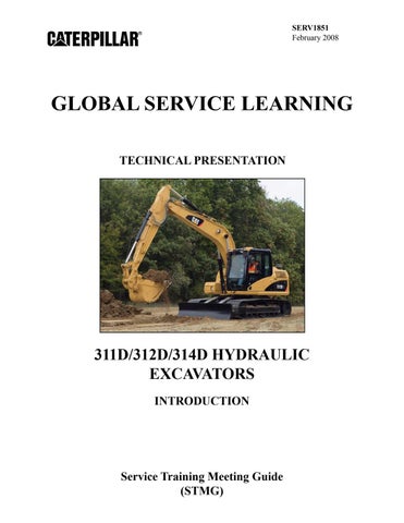
The left travel valve (1) and right travel valve (2)are used to control the travel motors. The straight travel valve (3)provides flow priority for the travel system during a travel condition.
The slow return check valve is part of the slow return check valve and cooler bypass manifold (4).
The travel system uses foot pedals (5) or travel levers (6) to control the direction of machine travel.
Each track is driven by a travel motor (7). Acounterbalance valve (8) prevents overspeed while the machine is traveling downhill, prevents shocks to the system when travel is stopped, and helps to prevent motor cavitation. Crossover relief valves (9) are used to protect the travel motor from pressure spikes. The upper supply line (10) directs supply oil to the motor for reverse travel, while the lower supply line (11) directs supply oil to the motor for forward travel. The travel motor turns the final drive. The final drive is composed of a three stage planetary gear reduction to reduce the motor speed to drive the track.
2
3
1 164
4
165
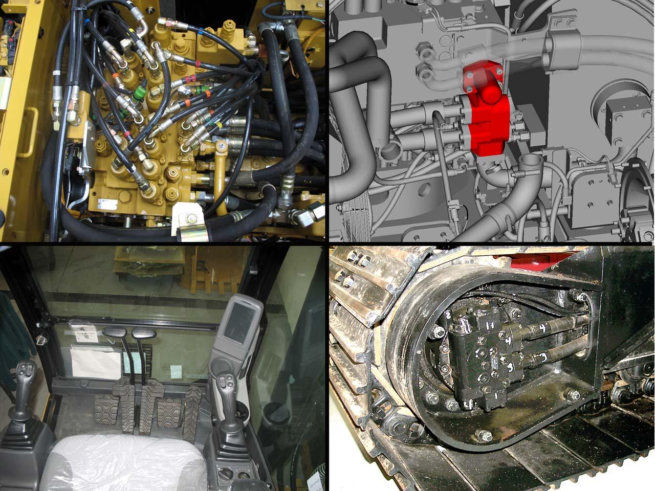
The two speed travel solenoid valve (1) is part of the pilot manifold. The manifold is located near the main control valve.
The hydraulic activation solenoid (2) must energize to shift the hydraulic activation valve (3). If the hydraulic activation valve is not shifted there is no pilot oil to the travel pilot valves.
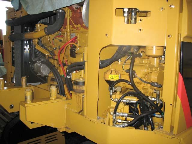
When the two-speed travel soft switch (4) is pushed, the travel speed is toggled between low and auto.
- The rabbit indicator indicates auto speed. - The tortoise indicator indicates low speed.
166
The travel pilot control valve operates similar to the implement pilot valves.
Depending on how far the the travel pedal or lever is moved will determine the amount of pilot oil directed to the respective travel control valve.
Adampening function is built into the travel pilot control valve which allows the operational speed of the travel lever/pedal to correspond to the movement of the operator's foot. The dampening function also prevents the vibration that occurs when the travel lever/pedal is released.
When the travel lever/pedal is moved from the NEUTRALposition, the rod is pushed downward. The rod moves the dampening piston downward. The hydraulic oil below the dampening piston is pressurized. An orifice check valve allows the trapped hydraulic oil below the dampening piston to gradually flow into the metering spring chamber, which is open to the tank. The gradual flow of oil through the orifice check valve provides the dampening function.