2 minute read
Return Hydraulic System


105
Return Hydraulic System
The return hydraulic system transfers all of the hydraulic oil that has been used in the system to do work back to the hydraulic tank.
The return hydraulic system has the following components:
- slow return check valve
- cooler bypass check valve group
- hydraulic oil cooler
- hydraulic oil filters
- hydraulic oil tank
106
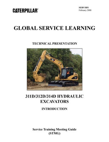
The slow return check valve and the bypass check valve are in the cooler bypass valve group (arrow).
The slow return check valve restricts return oil flowing from the main control valve, which maintains a constant back pressure in the return hydraulic system. The back pressure ensures that oil is available when needed for makeup in the various machine hydraulic circuits.
The bypass check valve regulates return oil flow through the hydraulic oil cooler.
107
Return oil from the main control valve flows from the return line to the slow return check valve. The back pressure created by the slow return check valve ensures that makeup oil is present at the various makeup valves in the hydraulic system.
After flowing through the slow return check valve, oil flows to the cooler inlet line and the bypass check valve. At low temperatures, the high viscosity of the oil flowing through the hydraulic oil cooler causes the pressure to increase. The increasing pressure causes the bypass check valve to open. Most of the oil flows through the bypass check valve. Because only a small amount of oil flows through the cooler, the oil temperature increases.
As the oil temperature increases, the bypass check valve begins to close and a greater portion of the oil flows through the hydraulic oil cooler. The bypass check valve maintains the oil at the optimum operating temperature.
2 1
108

The hydraulic oil cooler (1) is part of the cooling package (2) on the left side of the machine at the rear.
The hydraulic oil cooler reduces the temperature of the hydraulic oil in the system.
Oil enters the hydraulic oil cooler from the slow return check valve. After passing through the cooler, oil is delivered to the hydraulic return filter.
2 1 109

3 110
2
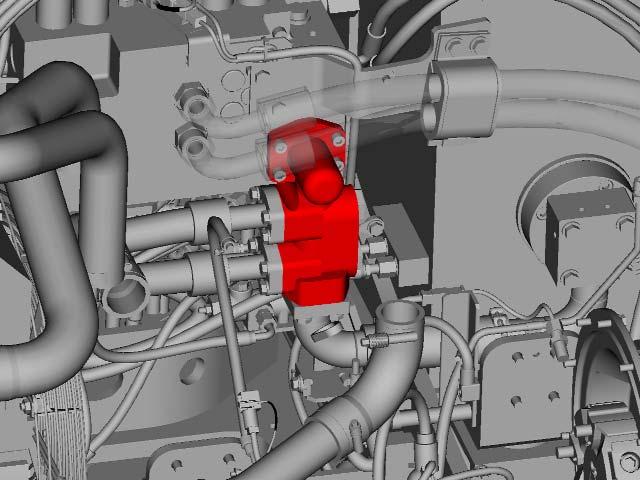
Return oil flow from the hydraulic oil cooler flows into the return filter (not shown), which is located in the hydraulic tank. The return filter contains a bypass valve that directs the return oil to the hydraulic tank if the filter becomes plugged.
All returning oil from the hydraulic system is filtered by the return hydraulic filter.
The tank has a vacuum breaker to limit the maximum tank pressure to 55 kPa (8 psi). The breaker opens at 13 kPa (2 psi) to prevent damage to the tank.
Oil in the hydraulic tank flows through the suction screen located inside the tank before being delivered to the main hydraulic pump group.
The hydraulic tank sight gauge (1) is located to the right of the pilot filter (2).
The case drain filter (3) receives case drain oil from the swing motor, idler and drive main hydraulic pumps, and left and right travel motors.
Oil from the case drain filter flows into the hydraulic tank. The purpose of the case drain filter is to reduce hydraulic contamination to the hydraulic system if a pump or motor fails.