2 minute read
Swing System Components


142
Swing System Components
The swing circuit controls the rotation of the swing motor. The idler pump provides the pump flow to the swing motor.
When either one of the joysticks is moved from the NEUTRALposition, the swing parking brake is released. The swing motor is mounted on top of the swing drive. The swing drive is installed on the upper structure and rotates the upper structure.
When the hydraulic activation control lever is in the UNLOCKED position, pilot pump oil flows to the swing parking brake solenoid valve in the pilot manifold and to the swing pilot control valve.
With the swing control valve in NEUTRAL, pump supply oil from the idler pump flows though the center bypass valve swing control valve to the NFC valve. The return oil creates a signal used to destroke the idler pump.
The swing brake is currently on so the motor will not rotate.
Since the implement hydraulic lockout solenoid has been energized, the hydraulic activation valve has shifted. Pilot oil is directed to the pilot joystick and the swing brake solenoid.
Swing Priority Valve: This valve provides flow priority over the stick control valve when the stick and swing are operated together.
Anti-reaction orCushion Relief Valves: These valves dampen pressure spikes in the swing system whenever the swing is stopped. The valves also inhibit counterrotation of the swing motor when the swing is stopped, which reduces swing "wag."
Slow Return Check Valve: The back pressure created by the slow return check valve ensures that makeup oil is present at the swing motor and the various makeup valves in the hydraulic system.
Swing Parking Brake Solenoid Valve: When energized the solenoid valve directs pilot oil to release the swing parking brake. The solenoid will energize when either one of the joysticks is moved from the NEUTRALposition.
1 2
3
4 6
7
10 8 9
5
143
The swing system uses one control valve (1) in the main control valve group (2) to control the swing operation.
The slow return check valve is part of the slow return check valve and cooler bypass manifold group (3).
The left joystick (4) in the cab is used to control the direction and speed of the swing.
The swing control valve directs oil to and from the swing motor (5). Additional swing motor components shown are the:
-swing drive oil level dipstick (6)
-crossover relief valves (7)
-anti-reaction valve group (8)
-makeup valve (9)
-swing motor case vent (10)
2 3
4
1
144
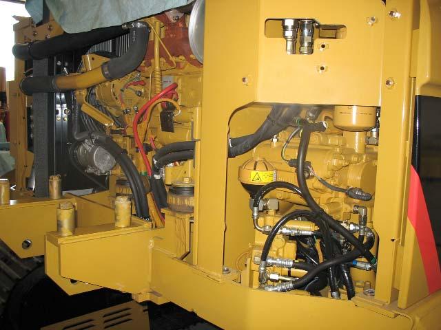
The swing brake solenoid valve (1) is part of the pilot manifold (2). The manifold is located next to the main control valve. The hydraulic activation solenoid (3) must energize to shift the hydraulic activation valve (4). If the hydraulic activation valve is not shifted there is no pilot oil to the swing brake solenoid valve and the swing brake cannot be released.
There is also no pilot oil available to the joystick pilot valves if the hydraulic activation valve is not shifted.