15 minute read
Main Control Valve Group


18
17
14 15 16 1
2
13
12
11 20 21
3
4
5
6 19
7
10 9 8
90
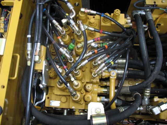
Main Control Valve Group
The main control valve group is located in the center of the upper structure of the machine. The main control valve group receives pilot oil signals from the operator controls in the cab. Each pilot signal then causes the appropriate control valve to shift in the correct direction.
When a control valve shifts, oil flows from the main hydraulic pumps to the appropriate hydraulic cylinder or hydraulic motor to perform work. The 311D/312D/314D main control valve is similar to the "C" Series valve. The components shown above include:
-auxiliary control valve (1) -stick 1 control valve (2) -swing control valve (3) -left travel control valve (4) -right travel control valve (5) -boom 1 control valve (6) -attachment line relief valve (7)
-bucket line relief valve (8) -attachment control valve (9) -bucket control valve (10) -stick 2 control valve (11) -boom 2 control valve (12) -boom head end line relief valve (13) -boom lower solenoid valve (14) -main relief valve (15) -pilot pressure switches (16) -stick regen control valve (17) -swing priority valve (18) -stick rod end line relief valve (19) -attachment flow control valve (20) -attachment line relief valve (21)
91
The above illustration shows a cross-sectional view of the main control valve group as viewed from the front of the machine.
The main control valve group is constructed of two valve blocks that are connected together. The front valve block is shown on the left and the rear valve block is shown on the right.
The drive pump provides oil flow for the right side of the main control valve group. The idler pump provides oil flow for the left side of the main control valve group.
The pilot-operated, open-center control valves are of parallel feeder design. Because the main control valve group uses the open-center portion of the control valve to generate a NFC signal for the pumps, the oil must have another path to deliver oil to the work ports. This is accomplished through a parallel feeder path. Aparallel feeder path runs parallel to the open-center path and supplies oil to the work port of each implement valve.
When all of the joysticks and pedals are in the NEUTRALposition, drive pump oil flows through the drive pump inlet port to the right half of the main control valve group. In the right half of the main control valve group the oil flows two directions; to the center bypass passages, and to the parallel feeder passages.
The oil in the center bypass passages flows in series through the center bypass passage of the right travel, the boom 1, the attachment, the bucket, and the stick 2 valves to the right NFC control orifice. The NFCcontrol orifice allows the oil to return to tank with a restriction.
This restriction is the NFC signal that is sent to the drive pump to maintain the drive pump at minimum angle. The NFC circuit and its components will be covered in greater detail later in this presentation.
The oil in the parallel feeder passage flows in parallel to the boom 1, the attachment, the bucket, and the stick 2 valves. When all of the valves are in NEUTRAL, the oil in the parallel feeder is blocked by the valve spools, and all oil must flow through the center bypass to the tank.
The oil from the idler pump flows similarly through the left half of the control valve when all valves are in NEUTRAL.
92
Control valve operation is similar for all of the valves in the main control valve group. The following explanation is for the basic operation of all of the valves in the main control valve group. The variations in each individual valve will be discussed later in more detail.
The control valve above is shown in NEUTRAL.
Spring force centers the valve spool to NEUTRALwhen there is no pilot oil pressure directed to shift the spool. In the NEUTRALposition, the spool blocks the oil in Port Aand Port B.
Oil flows from the pump to the parallel feeder passage. The load check valve is seated because of the pressure differential and spring force present on the load check valve.
In NEUTRAL,the valve spool allows oil to flow unrestricted through the center bypass passage, which directs a high NFCpressure signal to the pump control valve. The high NFC pressure causes the pump to destroke to a standby condition.
93
When the operator begins to move the joystick to shift the control valve, metered pilot pressure causes the control valve to shift slightly.
With the spool initially shifted, the center bypass passage is partially closed. This movement causes NFCpressure to decrease, which signals the pump to begin to upstroke.
The movement of the spool partially opens a passage allowing the oil from Port B to work with the load check valve spring to keep the load check valve seated.
The load check valve prevents unexpected implement movements when a joystick is initially activated at a low pump delivery pressure. The load check valve also prevents oil loss from a high pressure circuit to a lower pressure circuit.
The combined force of the work port pressure from Port B and the force of the spring above the load check is greater than the pump supply pressure, causing the load check valve to remain closed.
94
As the operator moves the joystick farther, the pilot pressure on the end of the spool increases. The increased pilot pressure causes the spool to fully shift.
The center bypass passage is now closed, which blocks the oil flow to the NFC signal port to a pump control valve. When the NFC signal is reduced, the pump upstrokes and flow is increased. The increased flow can no longer return to tank through the center bypass passage. All oil now flows through the parallel feeder path.
The increased oil flow to the parallel feeder passage causes pressure to rise in the parallel feeder passage. The increased oil pressure overcomes the force of the load check spring and the workport pressure in Port B, which causes the load check valve to unseat. Oil flows out to Port B.
The oil returning from Port Aflows past the spool and returns to tank.
NOTE: The load check valve is a loose fit in the load check seat to allow leakage past the check valve from the spring chamber. Aseparate spring chamber vent passage is not required with this load check design.
95
This illustration shows the operation of the main control valve when only the bucket spool has been shifted.
All of the control valves in the left side are in the NEUTRALposition, and the center bypass passage is open. All of the flow from the idler pump flows through the center bypass passage to the NFC orifice. Because all of the oil flow from the idler pump is restricted by the NFC orifice, the NFC pressure is at maximum pressure. The NFC pressure flows through the control line to the idler pump control valve. The NFC pressure present at the pump control valve causes the pump control valve to move the swashplate to the minimum angle position. The output of the idler pump is decreased to STANDBYdue to the increased NFC pressure.
The bucket control spool is fully shifted by pilot oil when the joystick is fully moved to the down position. Flow from the drive pump flows into the right side of the main control valve and into the center bypass passage to the bucket control valve. Because the bucket control spool is fully shifted, all of the oil flow from the drive pump flows to the bucket cylinder. No oil flows to the NFC control orifice and no NFC signal pressure is generated. Because no NFC signal pressure flows to the pump control valve, the pump control valve moves the pump toward maximum angle. The drive pump output increases.
96
When the joystick is partially moved from the NEUTRALposition to perform a fine control operation, reduced pilot pressure shifts the control spool slightly to the left. The movement of the control spool partially opens a passage to Port B.
The movement of the control spool also partially blocks the center bypass passage, which divides the flow from the one drive into two flow paths. Aportion of the pump output flows through the center bypass passage to the NFC orifice at a reduced pressure. The remainder of the drive pump output flows through the parallel feeder passage and internal passages to Port B.
Because the oil flow from the center passage to the NFC orifice decreases, the pressure to the drive pump control valve decreases. The reduced NFC pressure causes the drive pump to move toward maximum angle. The drive pump output increases proportional to the reduction in NFC pressure.
97
The main relief valve (arrow) is located on the top of the main control valve group.
The main relief valve limits the maximum hydraulic system pressure. The main relief valve is a two-stage relief valve. The travel setting is higher to increase drawbar pull.
NOTE: The main relief valve is adjusted while operating an implement. The travel pressure setting is not adjustable.
98
Oil from the drive pump flows to the straight travel valve and to the parallel feeder path for the right implement valves. The straight travel valve also directs drive pump oil to the main relief valve, the right travel valve, and to the center passage of the right implement valves.
Oil from the idler pump flows to the straight travel valve, to the main relief valve, the left travel valve, and to the center passage of the left implement valves. The straight travel valve directs idler pump oil to the parallel feeder path for the left implement valves.
The drive pump oil and idler pump oil pressures work against the two check valves. The check valves ensure that only the higher pressure from the idler or the drive pump flows to the main relief valve. The check valves also ensure that flow from the highest pressure circuit does not enter the other if the pressure is lower.
For example, if the bucket was being closed at a high pressure and no other function was active, the left check valve would close (as shown in this illustration). The check valve would prevent the drive pump oil from flowing through the center bypass in the left circuit. This ensures that relief pressure occurs in a stalled condition.
The main relief valve is a two-stage relief valve, with an implement setting and a travel setting. When an implement valve is activated, the main relief valve works against spring force and a low oil pressure. The main relief valve operates at the low (implement) setting.
With the implement valve activated, pilot oil pressure increases and the implement pressure switch closes. The implement pressure switch sends a signal to the Machine ECM indicating that an implement has been activated.
99
When a travel valve is activated, pilot oil pressure increases and the main relief valve works against spring force and a higher oil pressure. The main relief valve operates at the high (travel) setting.
With the travel valve activated, pilot oil pressure increases and the travel pressure switch closes. The travel pressure switch sends a signal to the Machine ECM indicating that the travel function has been activated.
100
This illustration shows the pilot operated main relief valve in the OPEN position when an implement valve is activated.
The main relief valve operates at a lower pressure during an implement operation or a swing operation. During an implement operation or a swing operation, there is no oil flow from the pilot manifold to the end of the piston. The poppet is held in the closed position by spring force.
At lower system pressures the poppet is held against the seat by spring force. System pressure in the passage flows through the orifice into the spring chamber to the left of the dump spool. When the force applied by system pressure is less than the value of the left spring, the poppet remains seated, causing the oil pressure in the right spring cavity to equal system pressure. The combined force of the right spring and system pressure holds the dump spool to the right.
As the system pressure nears the main relief valve pressure setting, the force of the system pressure in the right spring chamber overcomes the force of the left spring. This causes the poppet to unseat, allowing system oil to flow around the poppet to the return passage. As the oil in the right spring chamber flows around the poppet, additional system pressure oil flows through the orifice into the right spring chamber at a reduced pressure.
System pressure overcomes the force of the oil pressure in the right spring chamber and the spring, causing the dump spool to move left. As the dump spool moves left, system pressure oil is allowed to flow to the return passage.
The amount of spring force acting on the poppet determines the main relief valve pressure setting. Adjustments to the main relief valve pressure setting are made by changing the spring force of the left spring.
101
This illustration shows the pilot operated main relief valve in the OPEN position when a travel valve is activated.
When the travel function is activated, the maximum system pressure increases. Pilot oil pressure acts on the left end of the piston. The pilot oil moves the piston to the right compressing the poppet spring to increase the maximum system pressure.
NOTE: The main relief valve is adjusted while operating an implement. The travel pressure setting is not adjustable.
102
The above illustration shows a line relief valve in the closed and in the open positions. The line relief valve is a combination single-stage relief valve, and a makeup valve.
At lower system pressures, the poppet is held against a seat by the force of the left spring. The circuit pressure in the passage flows through a cross-drilled orifice in the piston to the spring chamber to the left of the inner spool. When the force applied by system pressure is less than the value of the left spring, the poppet remains seated, causing the oil pressure in the lower spring cavity to equal system pressure. The combined force of the lower spring and system pressure keep the inner spool seated.
As the system pressure nears the line relief valve pressure setting the force of the system pressure in the right spring chamber overcomes the force of the left spring. This causes the poppet to unseat, allowing system oil to flow around the poppet to the return passage. As the oil in the right spring chamber flows around the poppet, additional system pressure oil flows through the orifice in the piston from the right spring chamber at a reduced pressure.
System pressure overcomes the force of the oil pressure in the right spring chamber and the spring, causing the inner spool to move to the left. As the inner spool moves left, system pressure oil is allowed to flow to the return passage.
The amount of spring force acting on the poppet determines the line relief valve pressure setting. Adjustments to the line relief valve pressure setting are made by changing the spring force of the upper spring. The position of the adjustment screw determines the spring force of the upper spring.
103
The above illustration shows a line relief valve in the closed and in the makeup positions. The makeup function of the line relief valve prevents cavitation and voiding in the various circuits of the hydraulic system.
Under normal operating conditions, the outer spool of the line relief valve is seated. The valve is held in the seated position by spring force and the hydraulic pressure in the spring chamber to the left of the inner spool.
If hydraulic circuit pressure becomes lower than the tank pressure, the pressure in the spring chamber is reduced. Tank pressure surrounds the outer spool, and creates a force on the step of the outer spool. This force unseats the inner and outer spools and oil flows from the return system to the lower pressure hydraulic circuit.
104
The NFC relief valves are located in the main control valve group next to the stick valve. One NFC valve controls the NFC signal to the drive pump and the other NFC valve controls the NFC signal to the idler pump. Both NFC valves work the same.
Oil enters the NFC orifice from the center bypass passage. The returning oil flows through the NFC orifices to the return passage when the system is in STANDBY. The orifices restrict the flow back to tank, which causes an increase in pressure through the center bypass passages. This signal is sent to the pump control valve of the main hydraulic pump.
When a hydraulic function is activated in the main control valve group, the center bypass passage is blocked. The NFC pressure at the pump control valve bleeds off through the NFC orifices to tank.
The NFC relief valve is normally closed by spring force. The NFC relief valve is not adjustable.
NOTE: The left and right NFCrelief valves can NOTbe swapped for diagnostic testing purposes.
The NFC relief valve only opens under sudden pressure spikes in the return system, which would occur if the pump was fully upstroked and the control valve returned suddenly to NEUTRAL.
Asudden pressure spike in the return system would cause high flow through the center bypass passage. The high volume of oil could not flow quickly enough through the NFCorifice to the return system. The high pressure generated in the center bypass passage would open the NFC relief valve, which would relieve the sudden pressure spike. The valve would return with spring force to the closed position once the NFC orifice would allow an adequate amount of oil for the pressure in the return passage to decrease.