STUDIO 3.2
ENGAWA (eŋ’ɡɑ:wɑ:) 縁側/掾側
Studio 3.1 Recap Plans Development Process Sections Elevations Landscape Design User Experience CLimate Emergency Response Structural Strategy Construction Sequence 1:5 Tactile Detail 3 11-13 4-10 14-15 16-17 18 19 20 Materiality + Acoustics 1:20 Section Fire Emergency Regulations Building Regulations Compliance 1:25 Physical Model Exhibition Outputs Studio 3.2 Reflections 21 22 23 24 25 26 27 28 29 30 30-31 Appendix
CONTENTS
RECAP - STUDIO 3.1
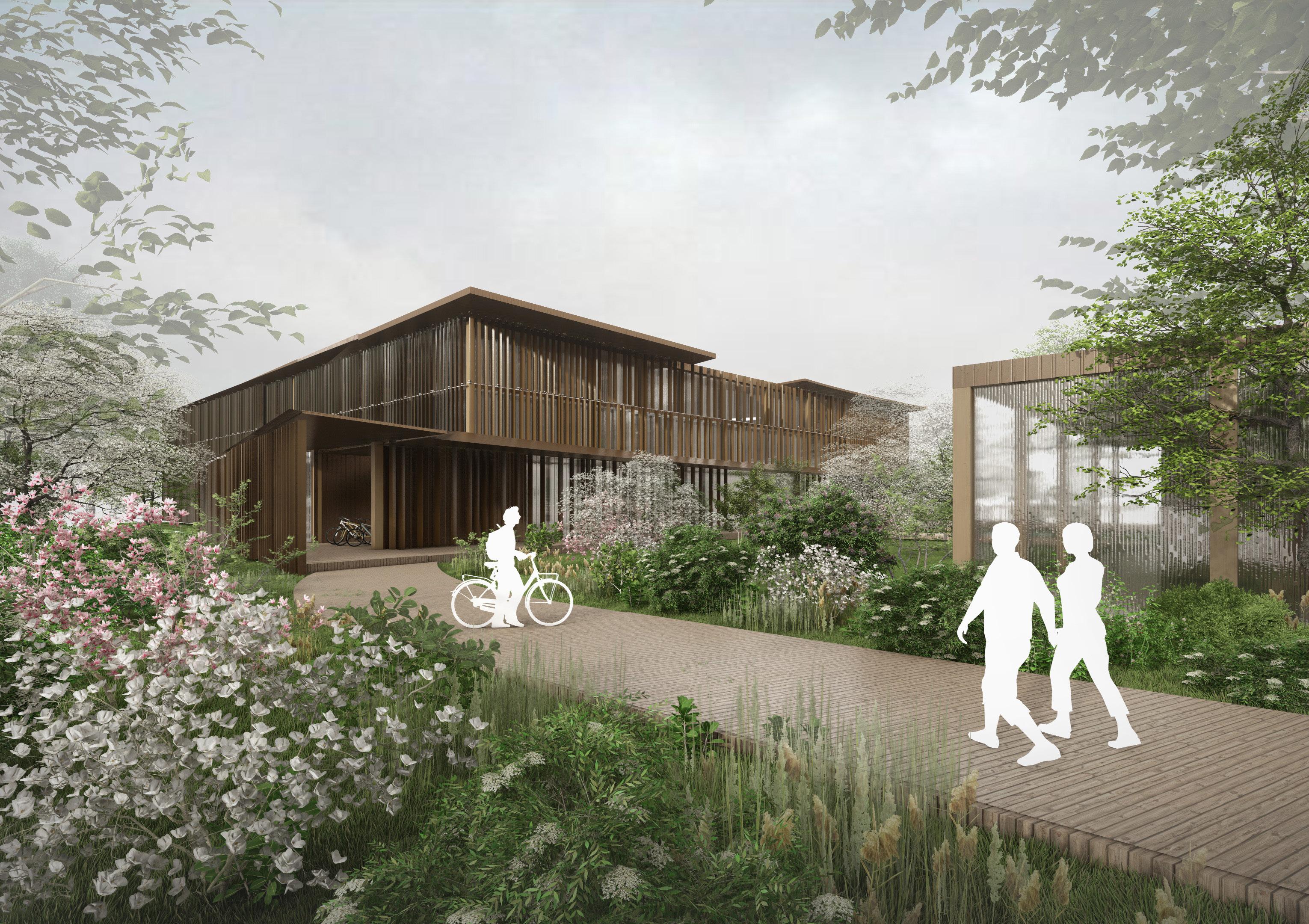
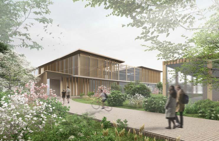
ENGAWA is a project that responds to the need of innovation and well-being consideration within university education. Through prioritizing users’ experience and its correlation with greenery, the project aims to rediscover the benefits of vegetation on teaching and learning, acting like a connector between architecture, human and nature.


ENGAWA aims to integrate the MMU Campus, through provision of multidisciplinary teaching and study rooms. In the wider scale it acts like a connector between campus and citizens, as it provides educational and recreational amenities open to the public. Thus strives for urban regeneration on multiple levels.
The Studio 3.1 project focused on sustainable, biophilic design, characterised by the open areas with greenery and flexible classrooms. Chosen programme, materials, construction methods remained the same, yet the details of the building performance required further iterations and refinition.
In Studio 3.2 the project was analysed and refined in the terms of space hierarchy, constructability and overal performance. The initial layout and form had to change to ensure functionality and efficiency of sustainable performance. For the same reason, the facade and roof design uired more consideration and adjustment to meet the expected standards as well as building regulations requirements.

BRIDGE
EPPING WALK
BIRLEY CAMPUS
MAIN CAMPUS
CAMPUS - MOVEMENT CONCENTRATION
DEVELOPMENT PROCESS
CONSTRUCTION GRID DEVELOPMENT
The plan synthesizing Studio 3.1 idea with atrium extension was then iterated to meet the structural requirements.

Further plan development with consideration of primary and secondary structure.
STUDIO 3.1 PLAN ATRIUM EXTENSION

Original plan required refinition in the terms of structural integrity. Moreover, some areas such as courtyard was not necessarily a beneficial solution due to the weather conditions, thus it required change.


ITERATION I ITERATION II
In the first iteration form of the structure was simplified for the structural reasons, yet it remained organic. The atrium was extended further to the south maximising the use of site space.

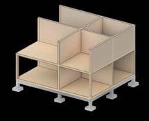
Loadbearing structure

CLT Walls and glulam columns

COURTYARD
In this iteration Structure is enclosed from the south creating inner courtyard or atrium extension. Such solution initially seemed reasonable, however, onc eapplied, the dimensions of sout part were inefficient - to small to locate the classrooms.
Secondary structure Partition walls
WALL STRUCTURE + ACOUSTICS


CONSIDERATION
STRUCTURAL INTEGRITY -
TIMBER STRUCTURE - ANALYSIS
Precedent Study: ‚Reinventer Paris’ Project by MGA Architecture.
Atrium extension
Outdoor space
Form
iteration
Analysis of typical CLT wall construction with acoustic panels. Analysing connections between loadbearing elementsfloor slabs and columns.
DEVELOPMENT PROCESS
PROGRAMME REFINITION

Throughout design process the project’s programme was refined, resulting in a more cohesive, integrated internal layout.
LETTING NATURE IN
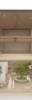
The projects wraps around the existing greenery and extends it inside the structure. The central atrium with vegetations provides the green views on each floor, contributing to user’s wellbeing and attention restoration.
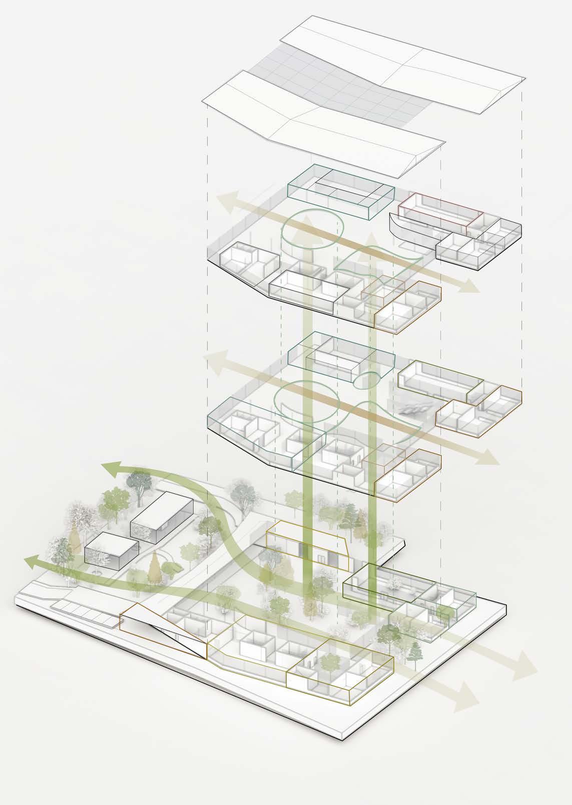
STUDY AREAS
Study areas are located on each floor, with first and second floor accessible only for students. The layout follows hierarchy set by atrium; the further to the building perimeter, the more enclosed rooms are, responding to different needs of users.
COMMUNITY ASPECT

Ground floor is accessible for the public and offers numerous studying facilities; classrooms, workshops, library, reading rooms to provide access to education for all residents of the area. It also includes recreational areas, dining room and garden
Group study areas
GREENERY

Main Access Route
Community Garden
Study pods Library
Silent study areas
Reading pavilion
Meeting Rooms
Classrooms
Atrium
Recreationa halls
CONNECTIVITY
Dining area Bike storage
DRIVERS
DESIGN
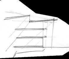
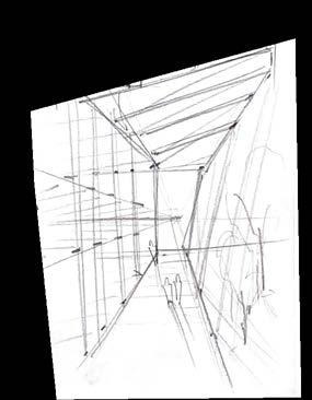
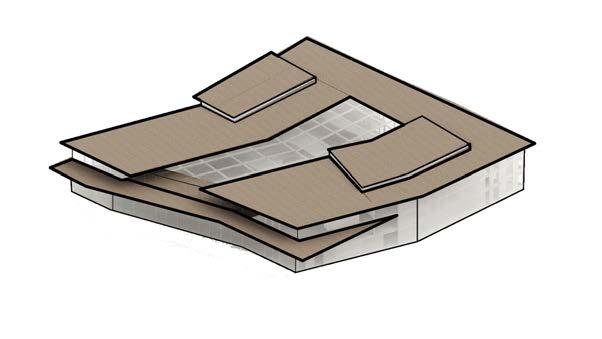
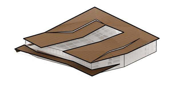
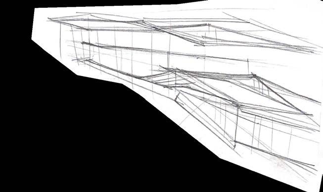
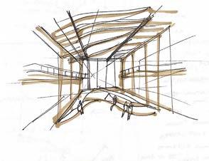
CONCEPT SKETCHES
STUDIO 3.1 STUDIO 3.2
UPLIFTED ROOF STRUCTURE FOR NATURAL DAYLIGHT
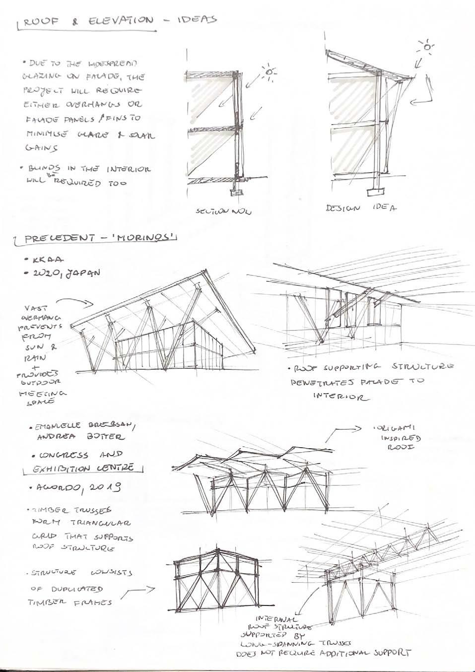
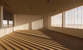
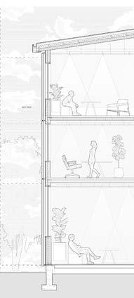
Consideration of passive nergy strategies - suspended facade with louvres and overhangs for glare protection.
FUNCTIONAL ELEMENTS INTEGRATED INTO ORGANIC ROOF STRUCTURE
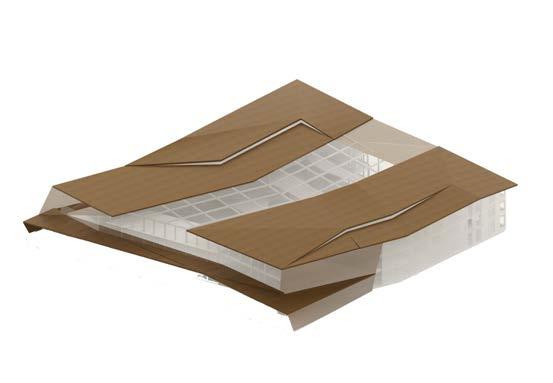
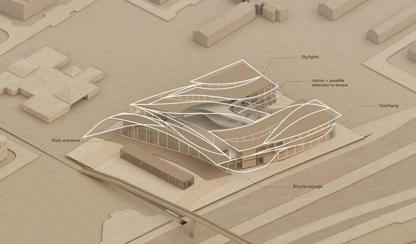
CONSIDERATION OF ROOF MATERIALITY
Conceptual sketchesexploring visual qualities offered by overhangs and organic roof structure.
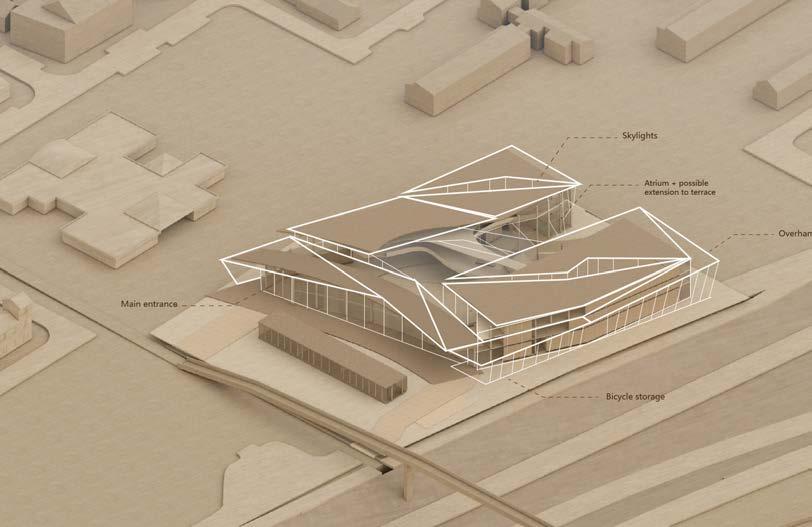
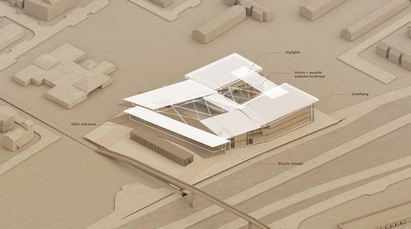
INTEGRATING BICYCLE STORAGE INTO FORM EXTENSION
SKYLIGHTS
DEVELOPMENT - 3D MODELLING
DEVELOPMENT DRAWINGS
DEVELOPMENT PROCESS
services integration
Services integration required several changes in the layout. After consultation with service engineer additional space for plant rooms, ventilation shafts and water tank was considered and included in fiinal design.

Electrical plant room
Mechanical plant room
Ventilation shafts
Water services distribution
Storage rooms
The main water distribution is provided through two cores, located in the west wing. The rainwater would be collected in the water tank located on the ground floor and then distributed around the structure to water the plants in atrium and adjacent garden. The water could be also used for flushing.
 Water tank
Cores including the toilets and service rooms
Water collection area in east wing.
Electrical plant room
Mechanical plant room
Ventilation shafts
Water services distribution
Storage rooms
Electrical plant room
Water services distribution + ventilation shafts
Rainwater distributed around the site to water plants inside and outside the structure.
Water tank
Cores including the toilets and service rooms
Water collection area in east wing.
Electrical plant room
Mechanical plant room
Ventilation shafts
Water services distribution
Storage rooms
Electrical plant room
Water services distribution + ventilation shafts
Rainwater distributed around the site to water plants inside and outside the structure.
DEVELOPMENT CONCEPT

Exploration and analysis of different facade ideas in the aspects of sustainable performance (glare and heat gains protection), flexibility, and suitability to programme (adjusting privacy levels)

Suspended facade acting as a sunscreen, that diffuses sunlight.

GLARE PROTECTION DESIGNATION OF SPACE
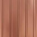
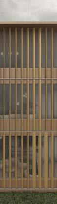
COPPER FINS
Creating distinction between areas of different purposes (for instance, meeting rooms and recreational rooms)
INITIAL IDEA
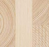
TIMBER FINS
Initial idea for cladding was to create a suspended facade with timber fins. Such design would provide diffused light in the interior and add to the privacy of users. Yet, timber cladding was not suitable choice due to the fire mergency regulations and weather. It also did not allow much flexibility to distinct areas of different usage and needs.


ITERATION I
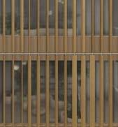
COPPER LOUVRES


In the second iteration parametric louvres were designed to ensure possibility of quick adjustment of number, distribution, rotation ankle through the algorithm. This option would provide both sun protection and flexibility, yet the size and movement of the panels required more research and consideration.


ITERATION II
CORTEN STEEL MESH
Another iteration explored the possibilities of corten mesh panels, which would rotate to a certain point, allowing users to decide on the level of sunlight and privacy. This iteration would work well for the aspect of daylight and privacy, yet, the movement of heavier panels would require energy, thus it would not be the most sustainable solution.
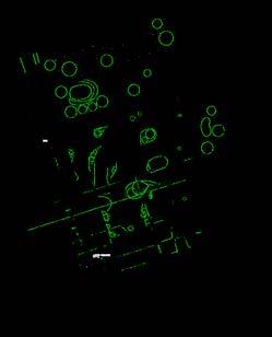
daylight analysis interior quality

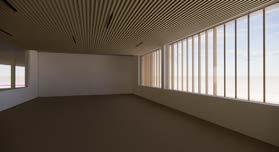
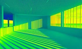
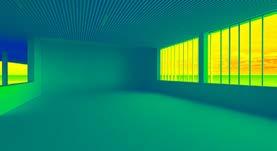
Analysis of the sungains over the day showed that the solution would be the most efficient; it would provide optimal light conditions as well as enable control over kinetic louvres to adjust privacy levels.
details
FACADE DEVELOPMENT
Detail drawing - joints + dimensions
FINAL ITERATION
3000mm 400mm 1200mm - 1500mm 220mm 110mm 200mm 200mm 110mm
Facade - steel joinery
8 am 12 pm LUX
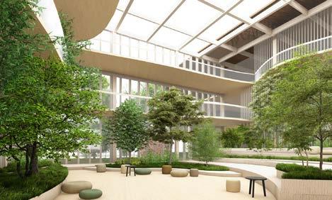
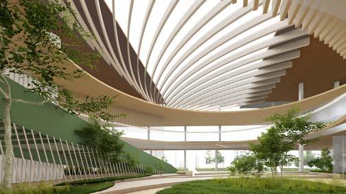
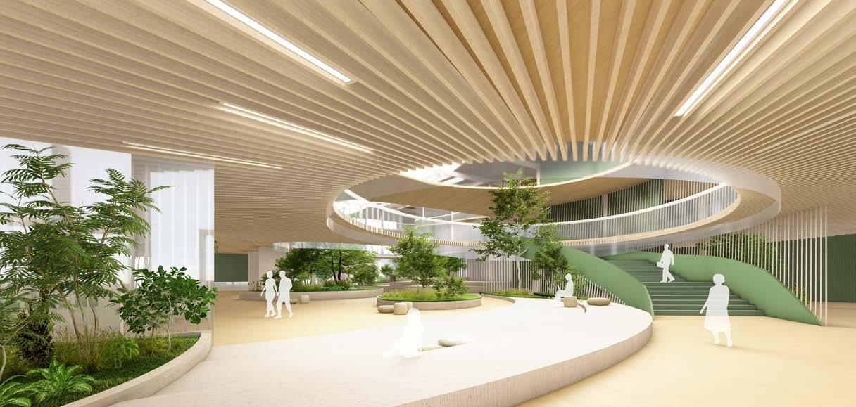
ATRIUM DESIGN
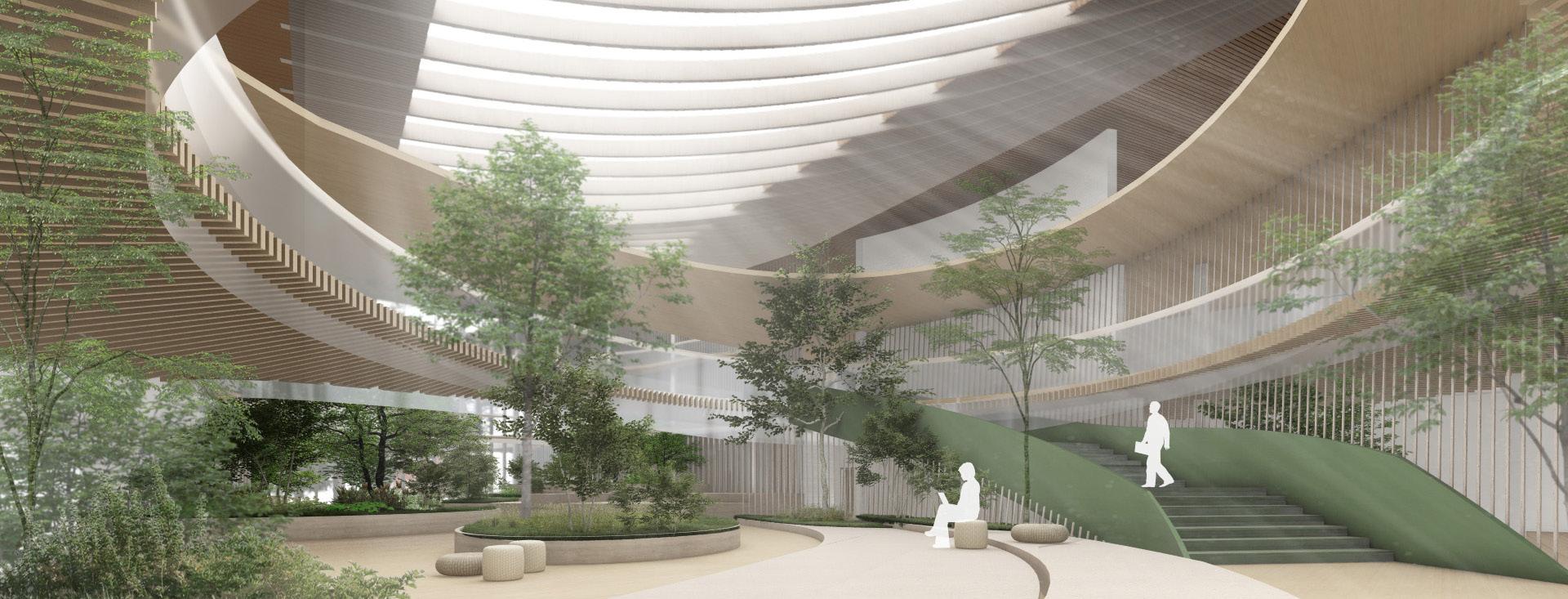
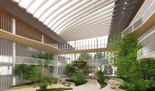
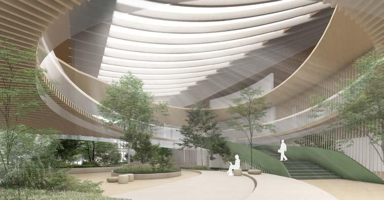
The main idea behind the atrium design was to let the greenery inside and blur the boundaries between nature and architecture. The atrium aims to utilize greenery’s benefits and provide calming, stimulating environment for meetings, study and events.
CONCEPT
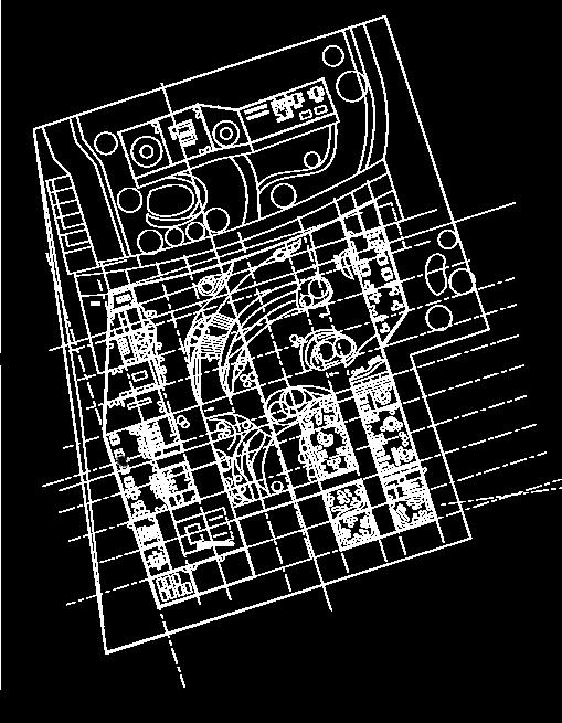
PARAMETRIC DESIGN
Ground floor plan - context
MEETINGS & EVENT SPACE
Central area would serve as an events space.
Atrium would also provide an entrance to the adjacent courtyard.
KEEPING EXISTING GREENERY
The form of atrium would be designated by the existing trees on site.

Concept sketchStudio 3.1 idea
In initial concept, the beams supporting atrium glazing were supposed to follow structural grid. Yet such design did not align with the organic layout of atrium and resulted in huge sungains and structure heating. Thus, a solution that would provide more shading was required.
DAYLIGHT FIRE PROTECTION
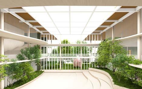
Atrium would provide natural daylight in the interior reducing the demand for artificial lighting. Open space layout and openings with polycarbonate sheets in classrooms enhance that effect and result in naturally lit rooms for most of the day.
Development sketch - para metric atrium design

Development sketch - parametric atrium design

In the fisrt iteration, the organic, parametric beams were tested. Although such design would provide more shading and create comfortable conditions for users, it did not match the rest of the design in the terms of visual cohesion.
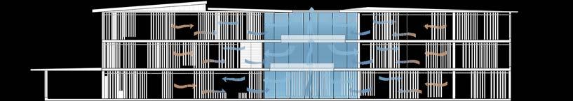
INITIAL IDEA ITERATION I ITERATION II VENTILATION
The final iteration was achieved after a set of experiments with parametric beams and their distribution. Eventually, satisfactory design was achieved: it simultanously provides daylight, but provides shade thanks to wider beams. The design also harmonizes with the organic forms of the atrium. For such design, prefabrication of specific glulam beams would be required.
Extended fire resistant glazing would prevent from fire spread in the event of fire.
Atrium design would enable natural ventilation n the structure and provide air circulation in the busisest areas.


PAVILION ITERATIONS
STUDIO 3.1 IDEA

The main issue with the pavilion structure was its position, which was to close to themain builidng, obstructing the views of the entrance. Such desicion was dictaded by the trees located on site, which I wanted to keep and integrate into garden design.
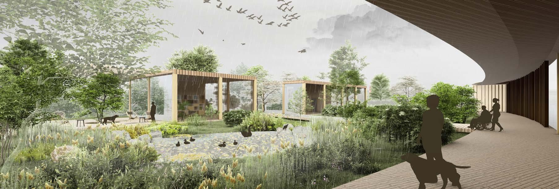
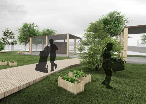
In Studio 3.2 several iterations were developed and analysed to resolve the pavilion design. Eventually, the structure of community pavilion was split into two, separate pavilions, one being designated for workshops and other wiith cafe and terrace. The structures would be connected by a wooden podest with the remaining tree in the centre.
PAVILION CONCEPTS
I. Structure moved to the north, the tree in the centre is kept on site and designates the form of pavilion.

II. Pavilion structure is reduced to an organic shape, combined with an open terrace with timer strips for shading. The tree would be incorporated into terrace design.


III. The structure is divided into two buildings - cafe and workshop area. The tree is located within terrace that connects two strustures.
 PEDESTRIAN ACCESS ROUTE
COMMUNITY GARDEN
BICYCLE PATH
ROAD FOR VEHICLES
DESIGNATED PATH FOR CAR PARK USERS
PEDESTRIAN ACCESS ROUTE
COMMUNITY GARDEN
BICYCLE PATH
ROAD FOR VEHICLES
DESIGNATED PATH FOR CAR PARK USERS
CAR PARK ACCESS ROUTE
COMMUNITY PAVILIONWORKSHOP AREA
COMMUNITY PAVILIONCAFE + TERRACE
PLANT
AND FOOD GROWING
POND + ANIMAL SHELTERING
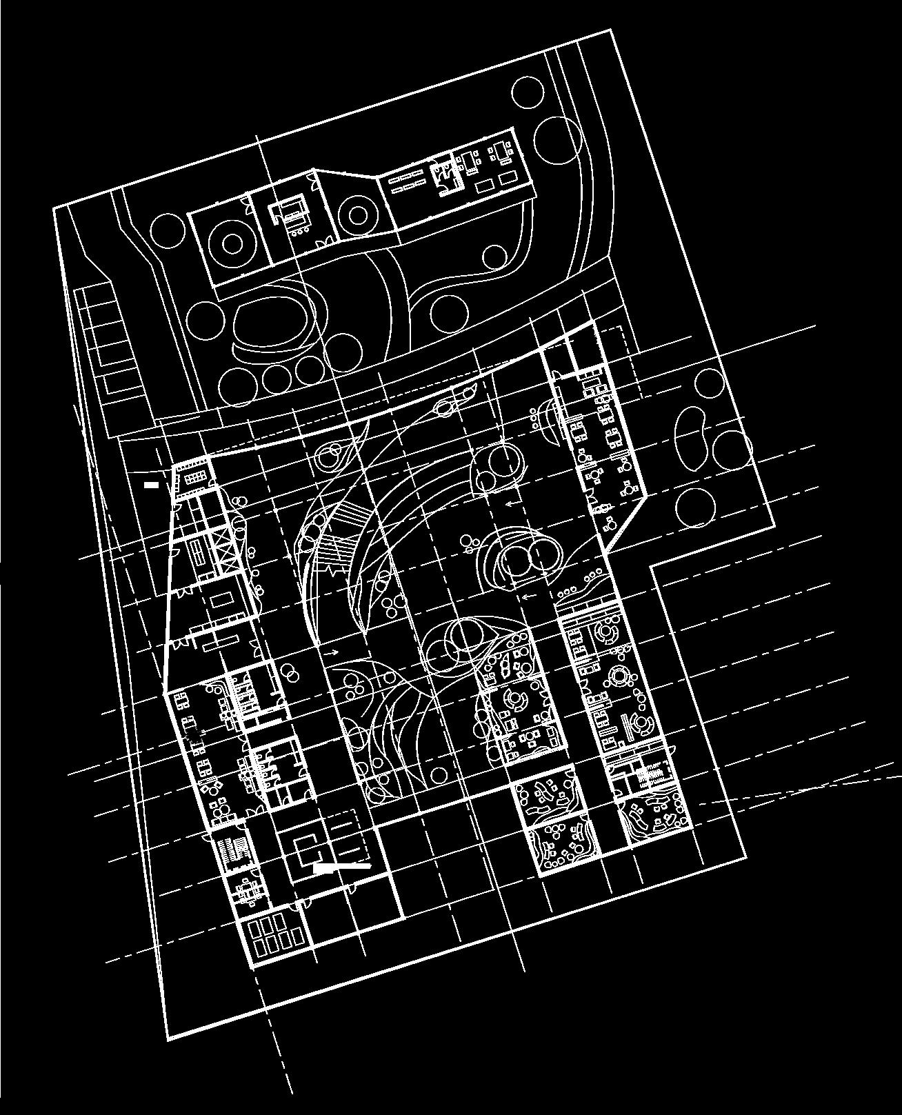
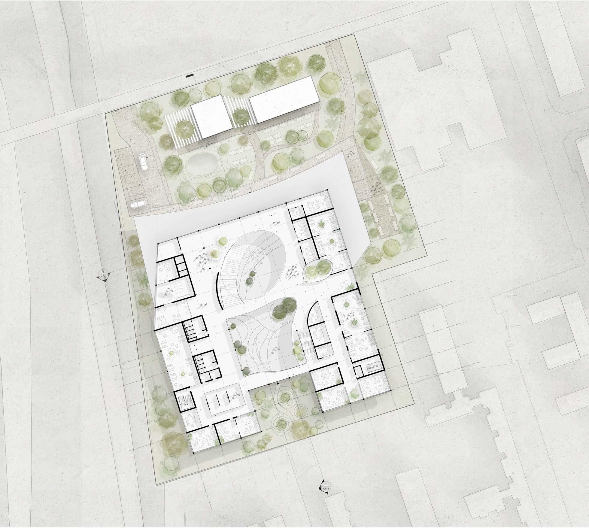
FINAL PLAN
GROUND FLOOR
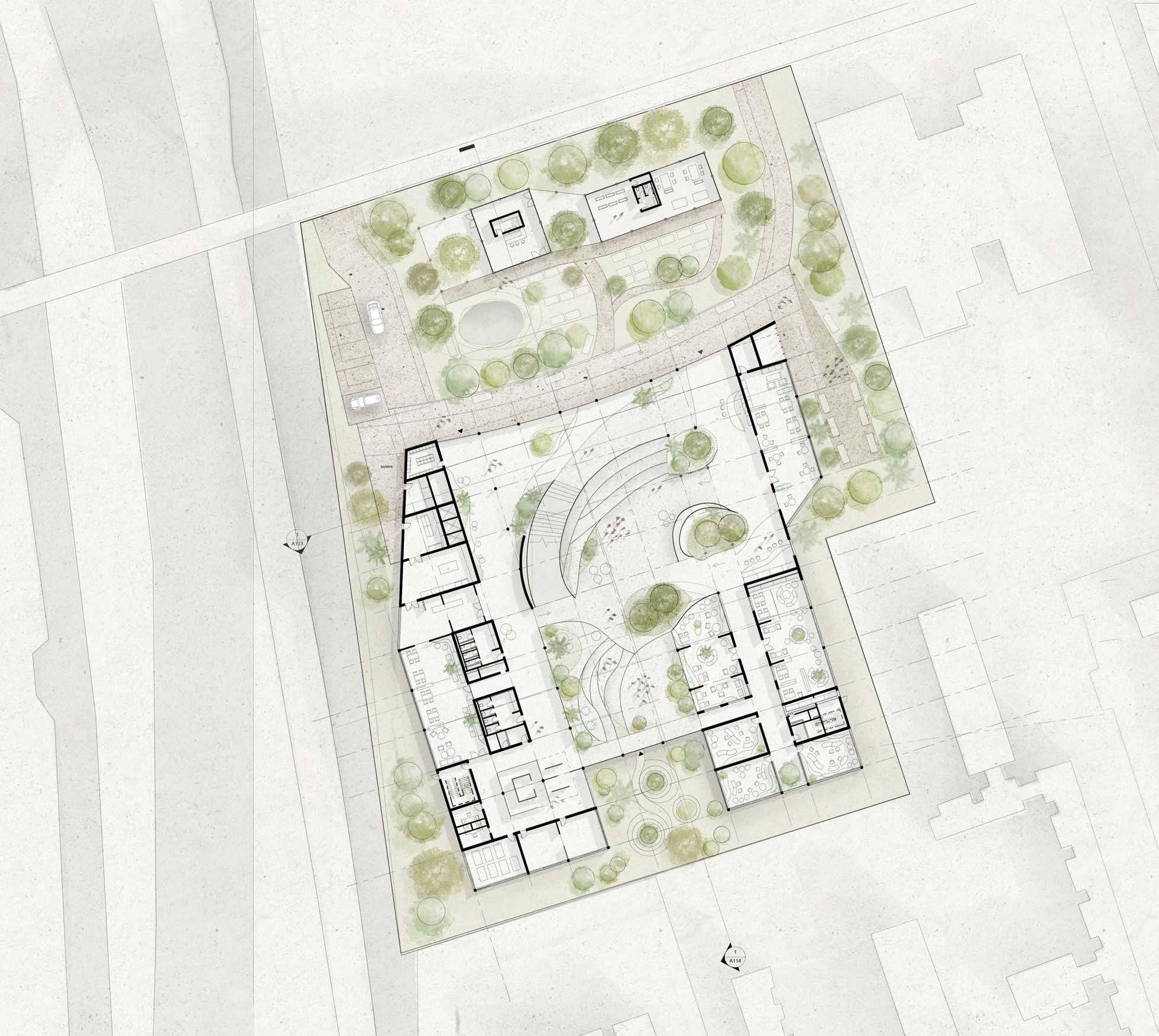 1. Atrium
2. Reception
3. Cafe
4. Open study & informal meeting
5. Dining area
6. Kitchen
7. Kitchen storage
8. Storage
9. Toilets
10. Adjustable workshop area
11. Recreational halls 12. Library
13. Reading pavilion 14. Courtyard 15.Classrooms 16. Community garden 17. Community garden 18. Garden workshop 19. Pavilion cafe & study area 20. Car praking 21. Bicycle Path
1. Atrium
2. Reception
3. Cafe
4. Open study & informal meeting
5. Dining area
6. Kitchen
7. Kitchen storage
8. Storage
9. Toilets
10. Adjustable workshop area
11. Recreational halls 12. Library
13. Reading pavilion 14. Courtyard 15.Classrooms 16. Community garden 17. Community garden 18. Garden workshop 19. Pavilion cafe & study area 20. Car praking 21. Bicycle Path
1 2 3 4 5 6 7 8 9 10 11 11 11 12 13 14 15 15 15 17 18 19 20 21 0 5 10
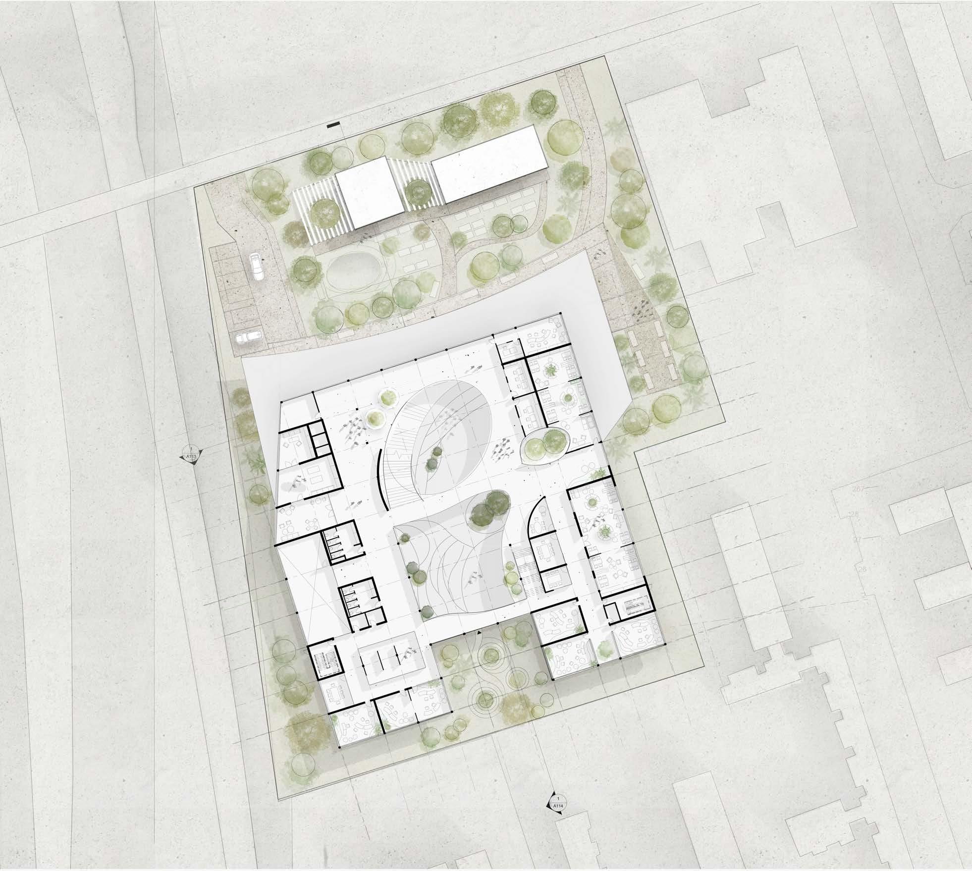
FINAL PLAN
1. Atrium
2. Lounge
3. Meeting rooms
4. Classrooms
5. Group study area
6. Quiet study area
7. Group study rooms
8. Kitchen for students
9. Toilets
10. Storage
FIRST FLOOR 1 2 2 3 3 4 4 5 6 7 7 8 9 10 11 0 5 10
11. Adjustable working/learning area
Second floor plan follows similar layout (see appendix).
Emphasizing the connectivity between Main Campus and Birley Campus.
Through greenery project aims to integrate students and residents and stimulate regeneration of Hulme.
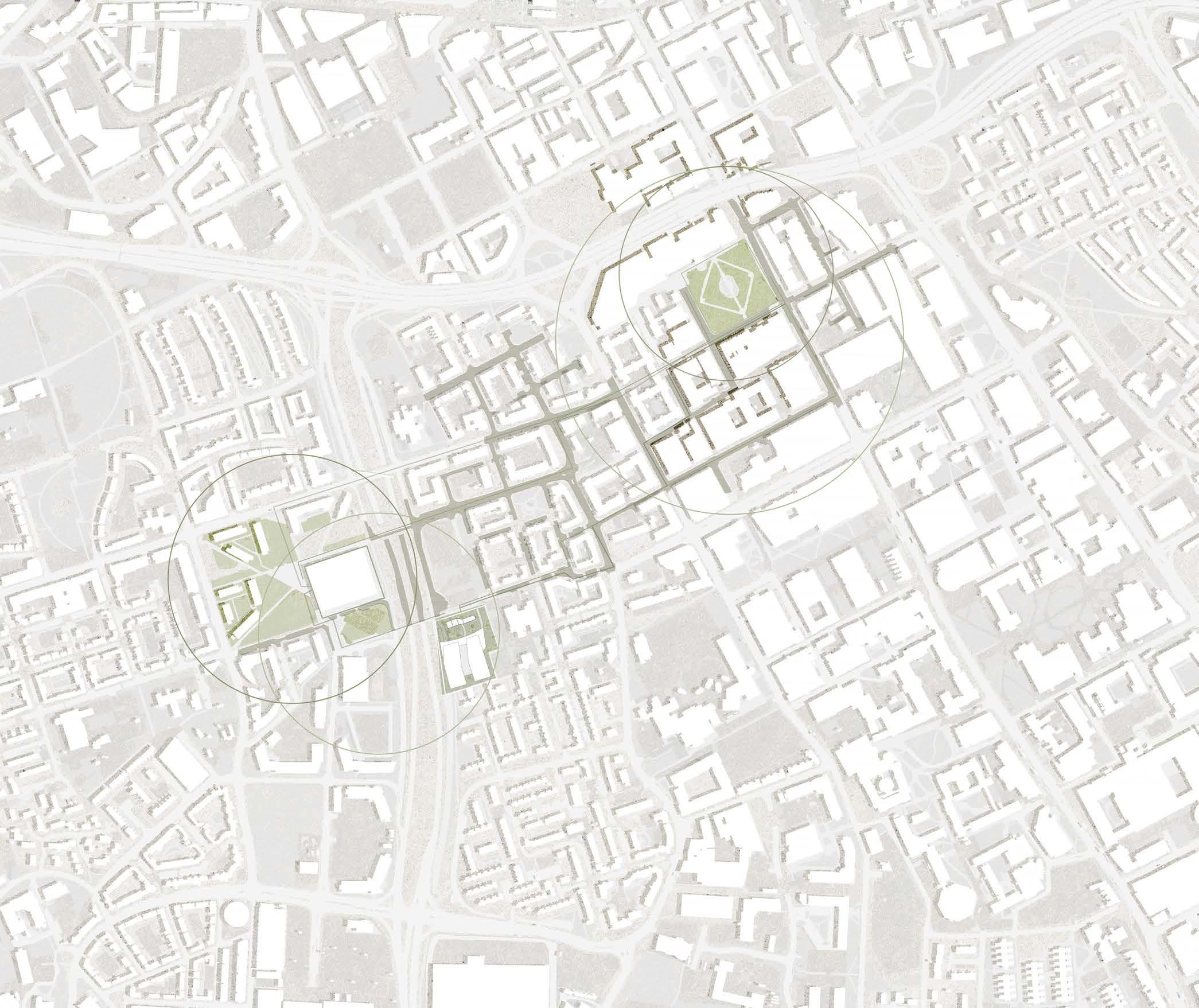
MASTERPLAN 50 100 25
SCALE 1:200
Scaled to fit the page
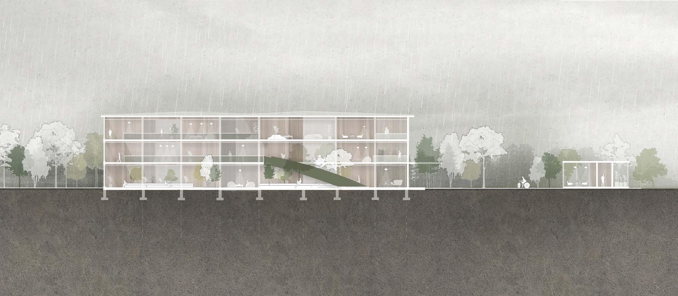
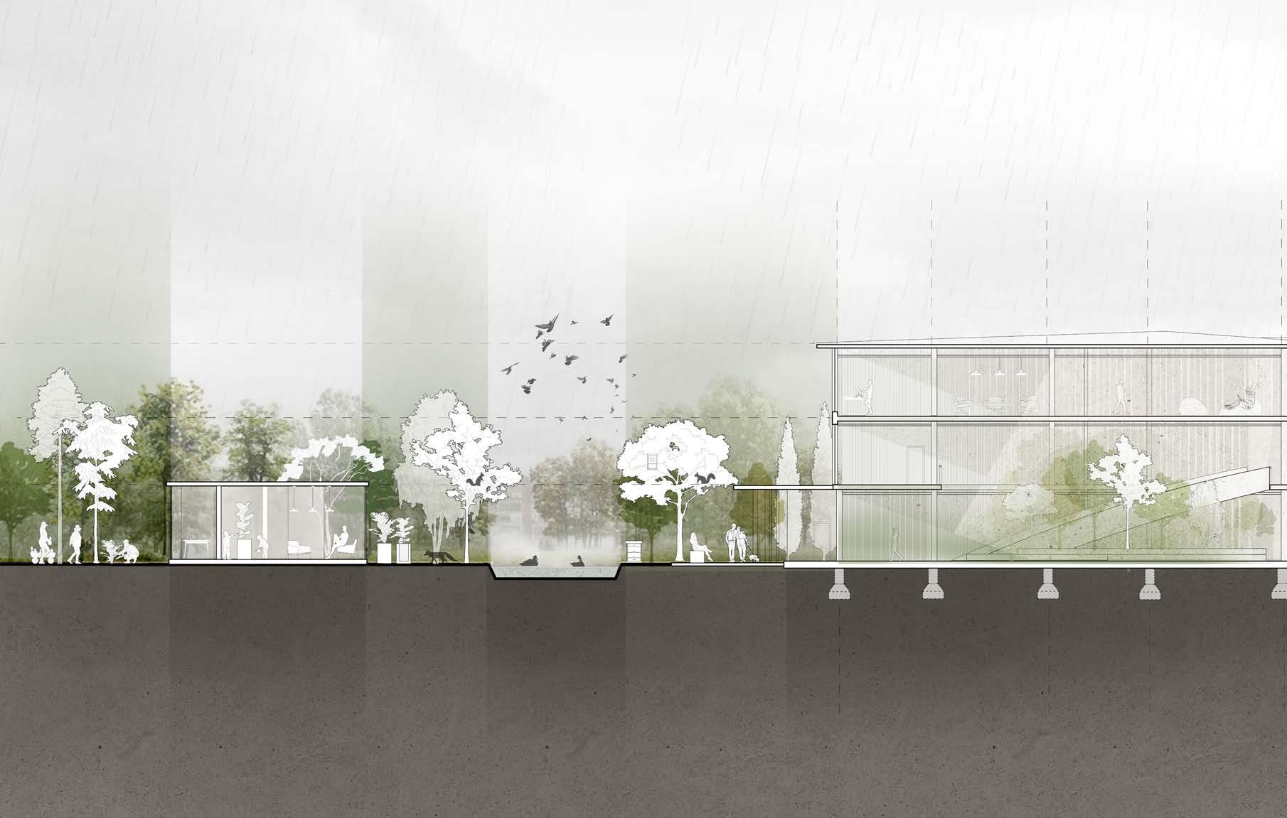
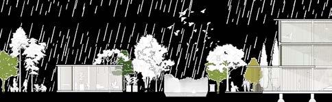
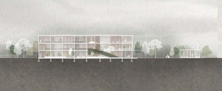
SECTION WEST 0 5 10
SCALE 1:200
Scaled to fit the page
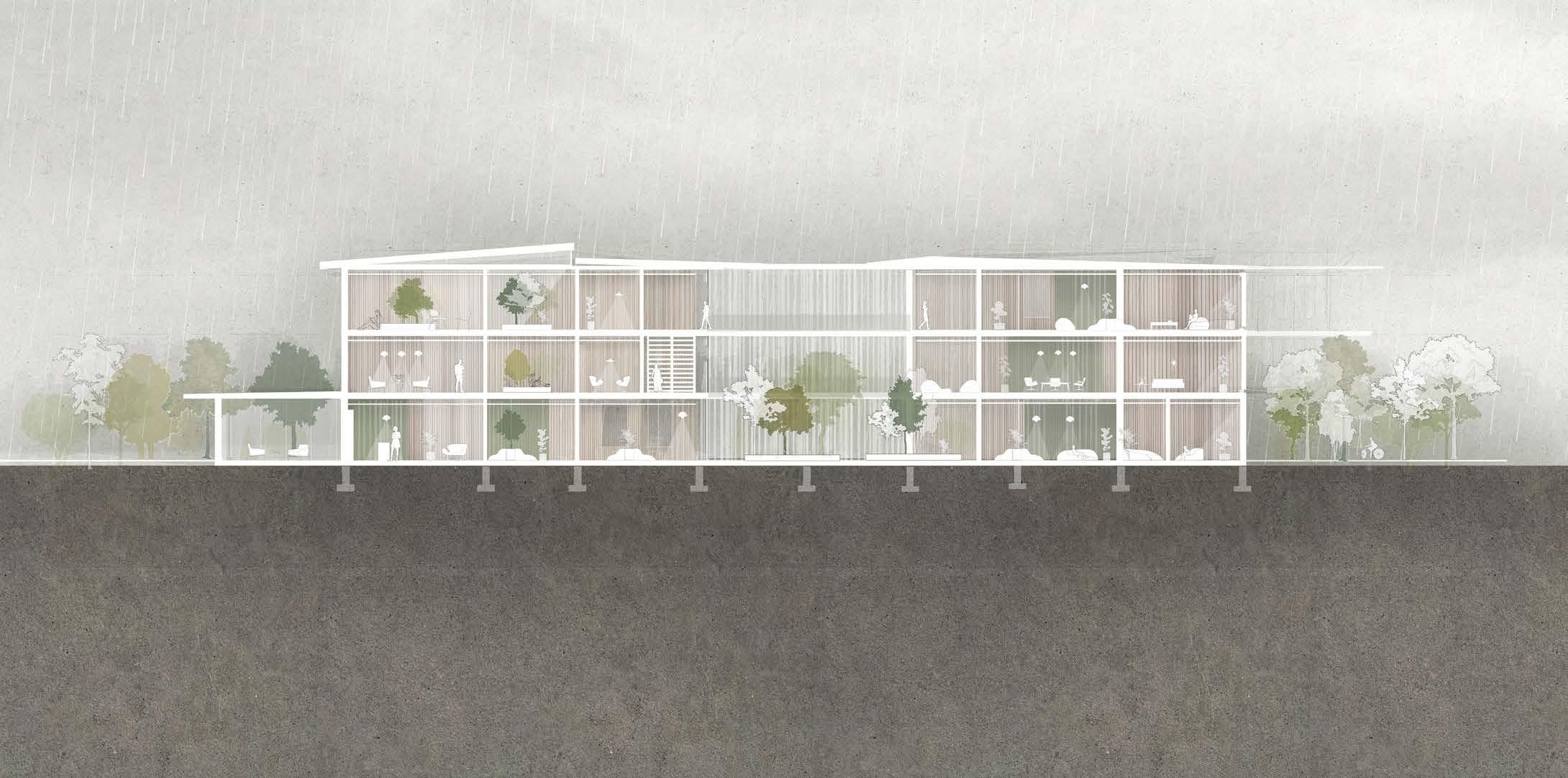
SECTION SOUTH
0 5 10
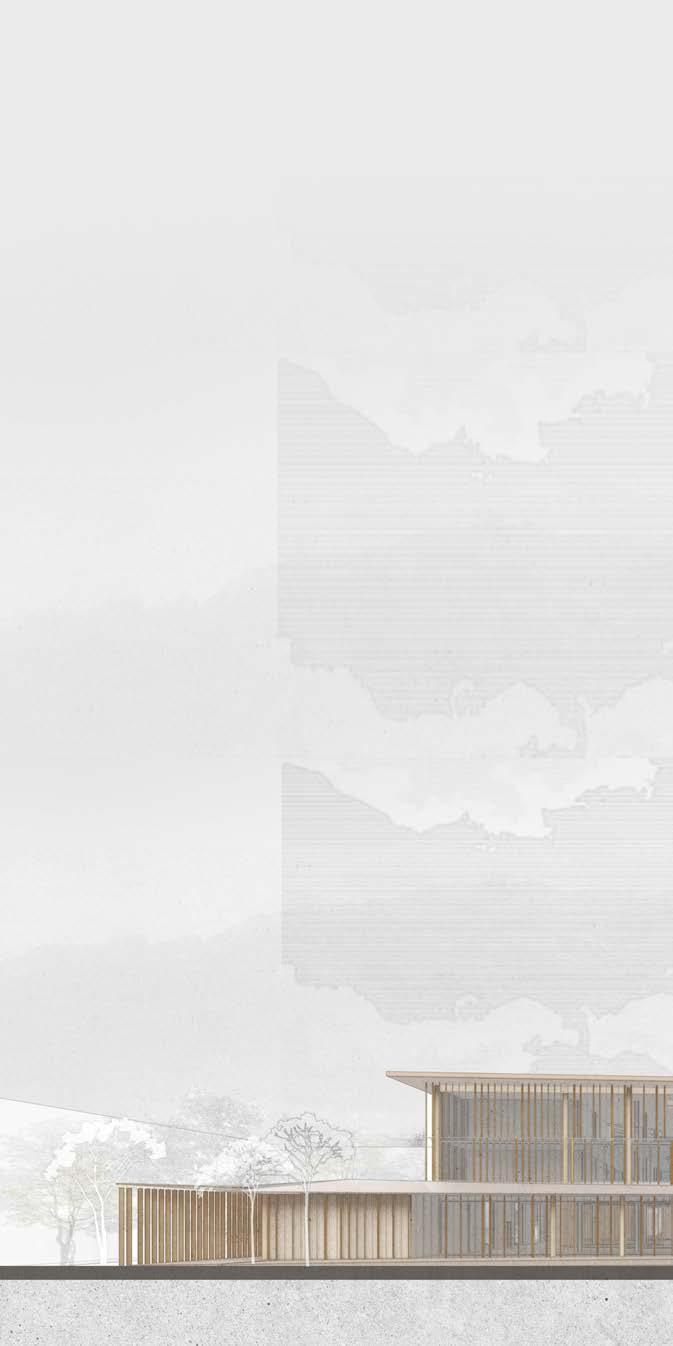
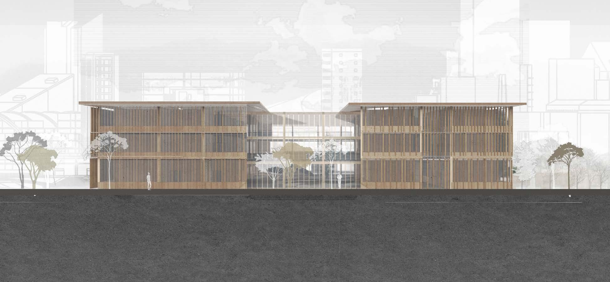
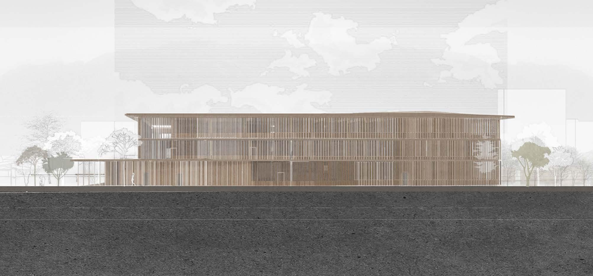
ELEVATION NORTH
SCALE 1:200
Scaled to fit the page
ELEVATION SOUTH
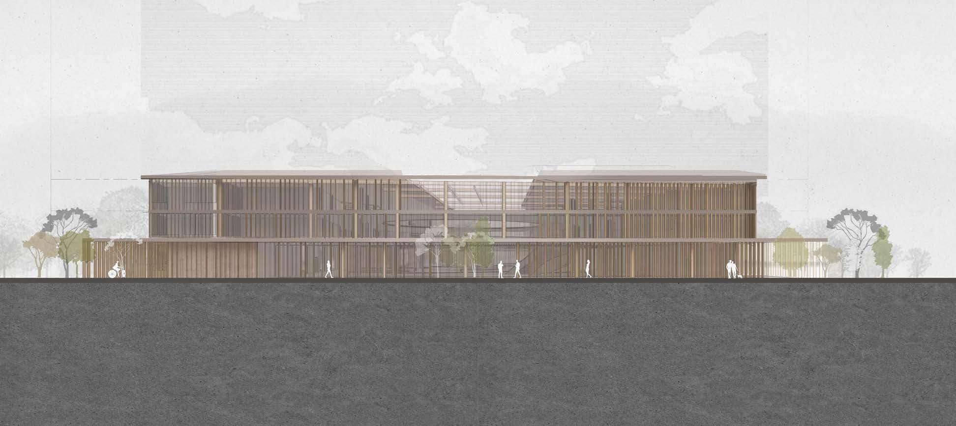
SCALE 1:200
Scaled to fit the page

0 5 10 0 5 10
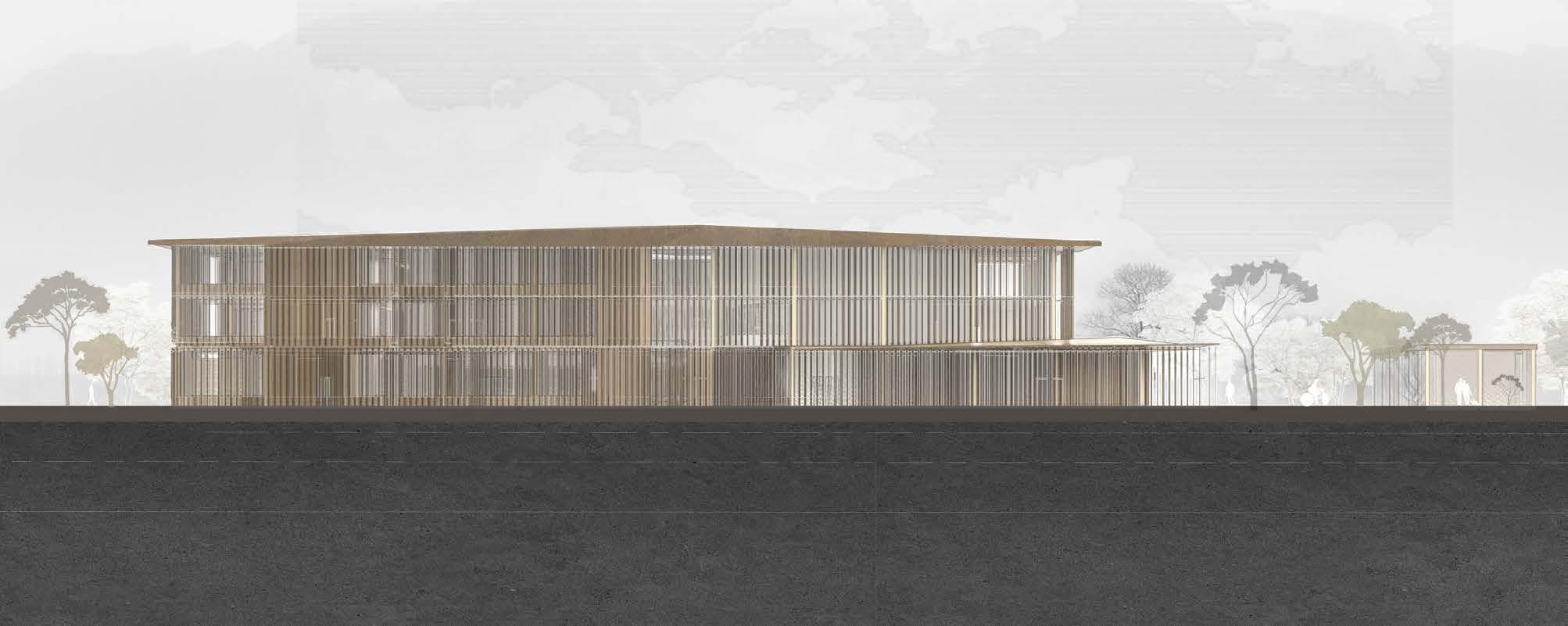
ELEVATION
WEST
SCALE 1:200
Scaled to fit the page
ELEVATION
EAST
SCALE 1:200
Scaled to fit the page
0 5 10
0 5 10
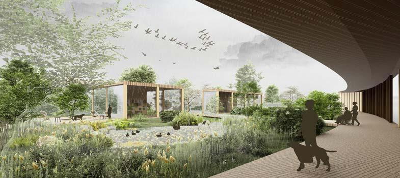
LANDSCAPE DESIGN
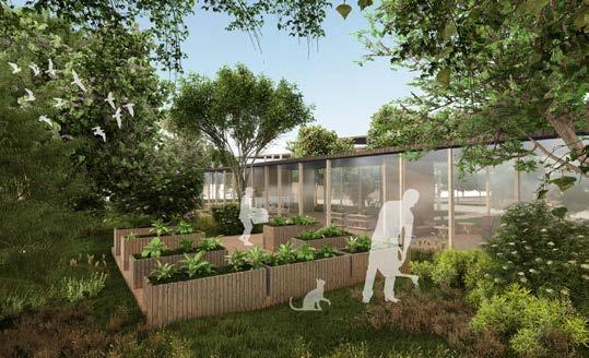
To provide landscape design, that would bring positive impact to existing natural environment, the species of local plants and animals were considered. The garden area would support regeneration of the green areas as well as rovide beehives and shelters for local birds and insetcs.
TOP VIEW

PLANTS CONSIDERATION
CULTIVATION OF NATIVE SPECIES

Common Ash
Black Poplar (Manchester) Poplar


Weeping Willow
SHELTER FOR LOCAL ANIMALS
INVERTEBRATES

Bees and Pollinators

Black garden Ant

Silver Birch Cherry
EDUCATION COMMUNITY ASPECT
Community integration through gardening activities.
Space for education about environment and food growth.

Red Fox

Bullfinch

Song Thrush


Grey Squirrel Red Squirrel Starling

Red Ant

Bumble bees
Common Wasp


Butterflies

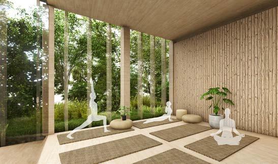
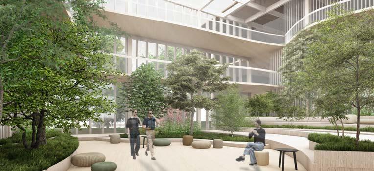
ANIMAL SHELTERS WELLBEING
Area for socialising and recreation.
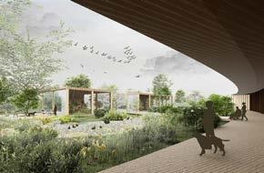
Extending the greenery to the interior allowing users to benefiit from communing with nature.

Improving well-being and overall performance of students through access to views on greenery.
 LETTING VEGETATION INSIDE VIEWS ON GREENERY
Provision of shelter for local animals, as well as beehives.
Examples of local animals and insect species that would benefit from the landscaping.
LETTING VEGETATION INSIDE VIEWS ON GREENERY
Provision of shelter for local animals, as well as beehives.
Examples of local animals and insect species that would benefit from the landscaping.
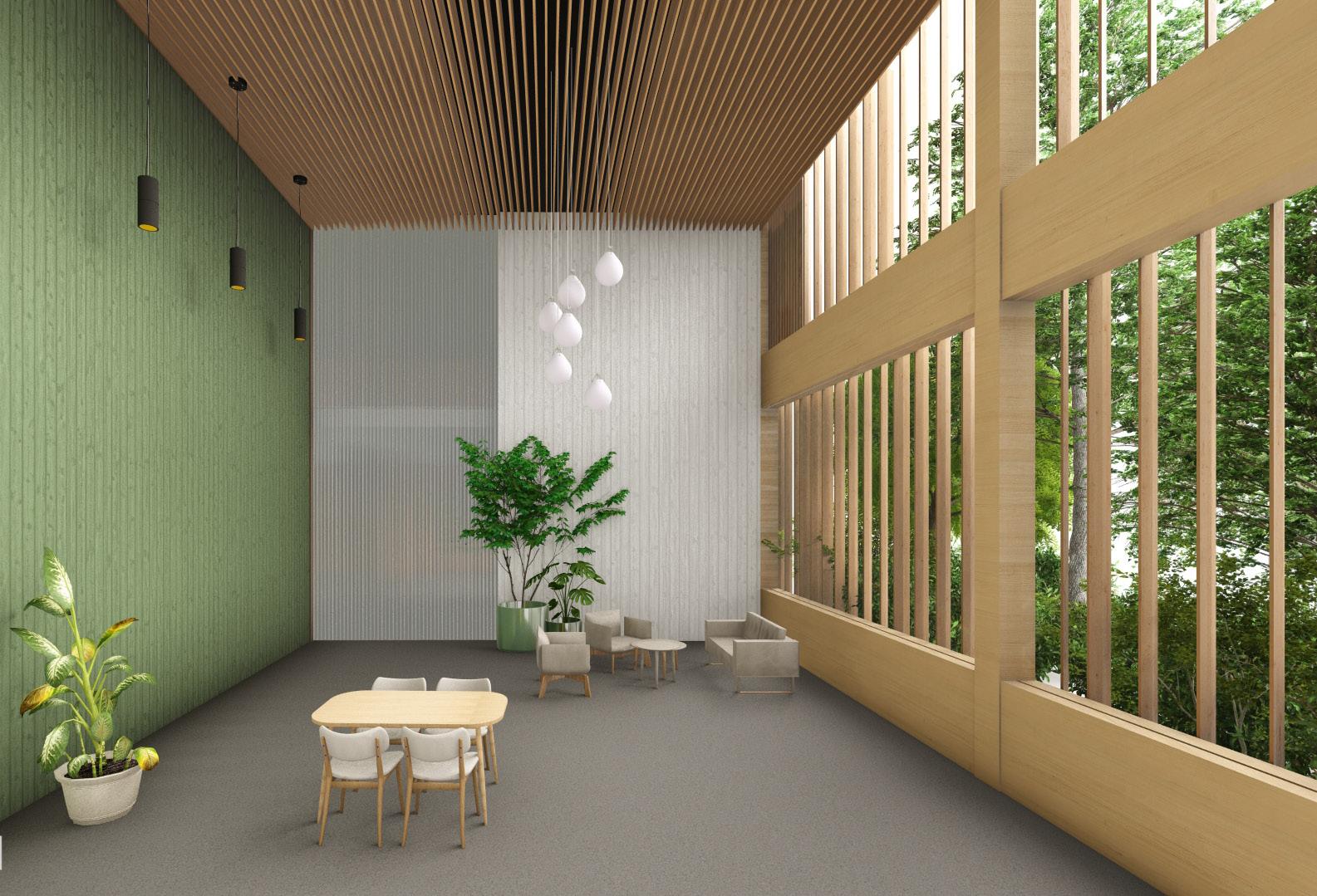
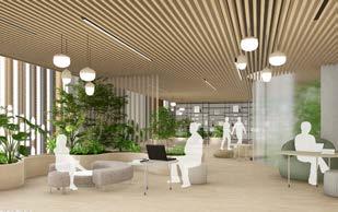
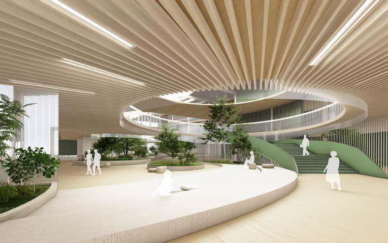
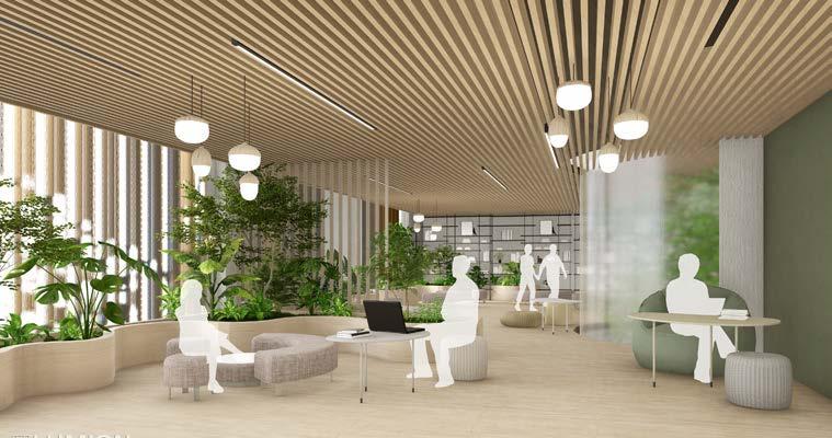
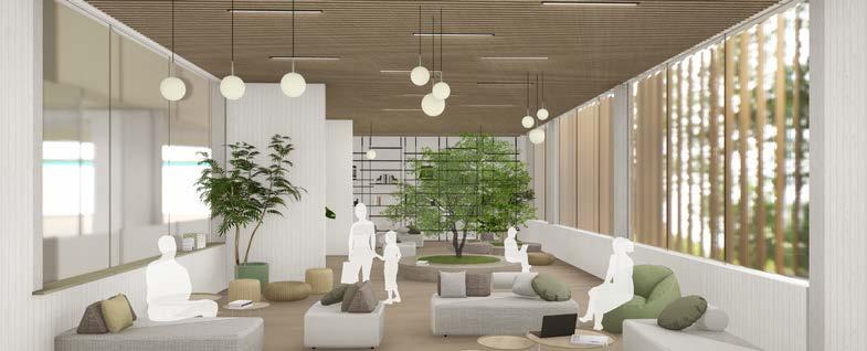
SPATIAL QUALITIES - USER’S ENGAGE

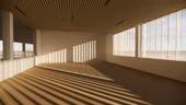
The project aims to prioritize user experience and contribute to the wellbeing and health of users, following the concept of user-centered design. Wide openings in each space allow daylight diffused by greenery to spread around and inside the building, promoting a sense of cosiness and safety with natural materials. Additionally, open, flexible spaces encourage social interaction, foster a sense of belonging, and facilitate multifunctionality.
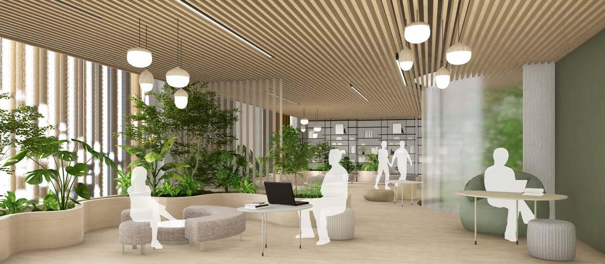
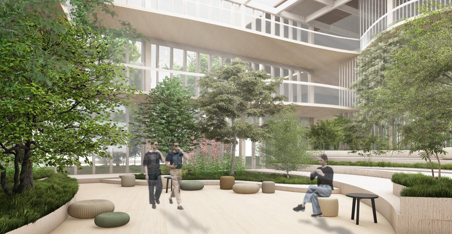
COMMUNITY GARDEN RECREATIONAL ROOMS
ATRIUM - SPACE FOR INTEGRATION AND EVENTS
CLIMATE EMERGENCY RESPONSE
RIBA SUSTAINABLE GOALS
PROVIDING SUSTAINABLE SOLUTIONS AS A FUNDAMENTAL PART OF DESIGN PROCESS

I. NET ZERO OPERATIONAL CARBON
I. Maximasing natural daylight through translucency of envelope - wide openings + shading, rotating fins allowing sun gains control.

II. Using solar panels as an energy source.
III. Incorporating skylights as an additional lighting source.
IV. Prioritizing the use of ultra low-energy appliances and equipment.
SKYLIGHTS
II. NET ZERO EMBODIED CARBON


I. Utilizing local timber - reducing the environmental impact of material transportation, encouraging ethical and responsible sourcing.
III.SUSTAINABLE WATER CYCLE
I. Implementation of water recycling system, that depends on the collection and filtration of greywater and rainwater.
II. Reuse rainwater for gardening and irrigation purposes.
III. Prioritizing the use of waterless and low-flow appliances, along with a leak detection system.
WATER COLLECTION SYSTEM
IV. SUSTAINABLE LIFE CYCLE COST
I. Conducting examination of the building’s present and future usage along with an estimation of its energy consumption and operational expenses.
II. Consideration of the added value of occupants’ health and well-being, as well as the sustainable outcomes of the project.
NATURAL VENTILATION
Atrium helps with natural ventilation inside the structure and provides natural light throughout the day.

V. SUSTAINABLE LAND USE & ECOLOGY
I. Strenghtening the role of site biodiversity through preservation of existing trees and greenery and integration into design.
II. Providing green spaces both outside and inside the structure, with the goal of rejuvenating the site’s vegetation.


III. Community garden serves as a space to foster and expand site biodiversity, including designated areas for cultivating food, which contributes to a more self-sustaining dining environment on-site.
IV. Incorporation of shelters for animals to support the presence of fauna on the site.

VI. SUSTAINABLE CONNECTIVITY & TRANSPORT
II. Minimizing the use of concrete (for foundations) and promoting low-embodied energy materials, as well as natural and recycled/recyclable materials.
III. Incorporating open spaces and multifunctional/learning halls, allowing for quick and cost-effective adjustments or repurposing in the future.
VII. GOOD HEALTH & WELLBEING
USER EXPERIENCE - COMFORT

I. Prioritizing pedestrian and bicycle routes. Designated pathways for pedestrians are implemented to enhance safety and promote walking. Creating a user-centric design that prioritizes well-being and health is a key motivation behind the project.
I. Spaces with natural daylight and strong connection to nature.
II. Provision for natural ventilation, acoustic comfort, and thermal control. The adaptability of spaces and visually comforting interiors will further enhance the user experience.
III. Design of planted areas, both outdoors and indoors, to harness the attention restoration and stress-reducing benefits of greenery.
IV. Promoting active circulation routes with designated pedestrian and bicycle paths.

VIII.
SUSTAINABLE COMMUNITIES & SOCIAL VALUE
The project aims to regenerate area of hulme through integration of local residents and students.
I. Including areas designated for public such as dining space, library, workshop rooms and community garden.
II. The development of building would also result in provision of additional working places, recreational areas for wellbeing and education sources for unpriviledged.
 FACADE - NATURAL DAYLIGHT
Bicycle path Bicycle
Vehicle road Car park with paths designated for disabled Pedestrian
path
path
CLT and glulam as a main structure
Concrete reduced to foundations and floor topping Internal finishes and partition walls using local timber, possibly recycled panels
Rainwater collected through drainage system. Water tank. Plant watering system.
Toilets.
STRUCTURAL STRATEGY STRUCTURAL GRID MODULARITY
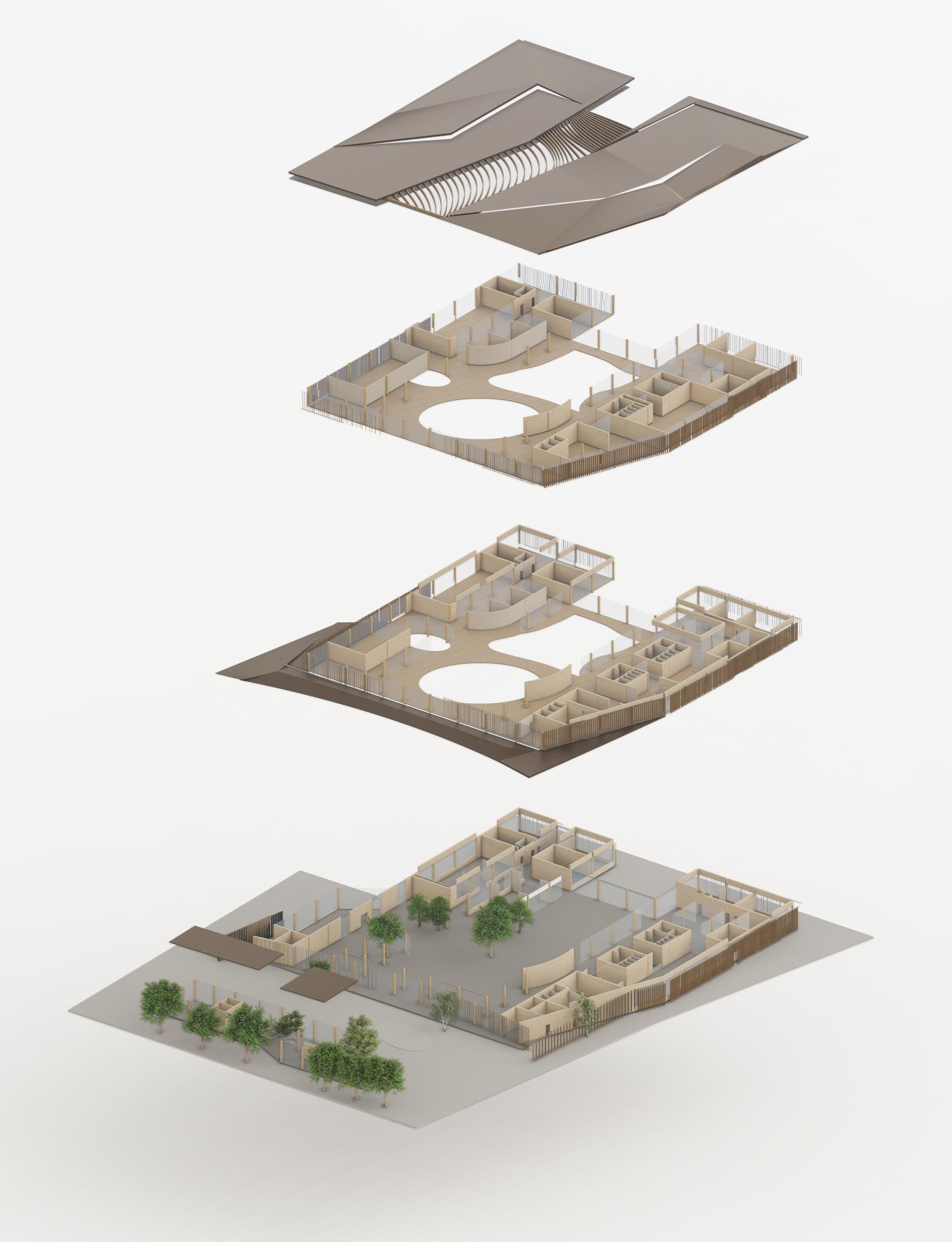
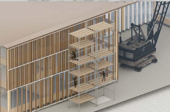
Modular CLT panels and glulam columns would enable faster and simplified construction process. The structures follows a grid of 6m and 8m alllowing application of timber structure in common sizes.
FACADE + WALL DESIGN
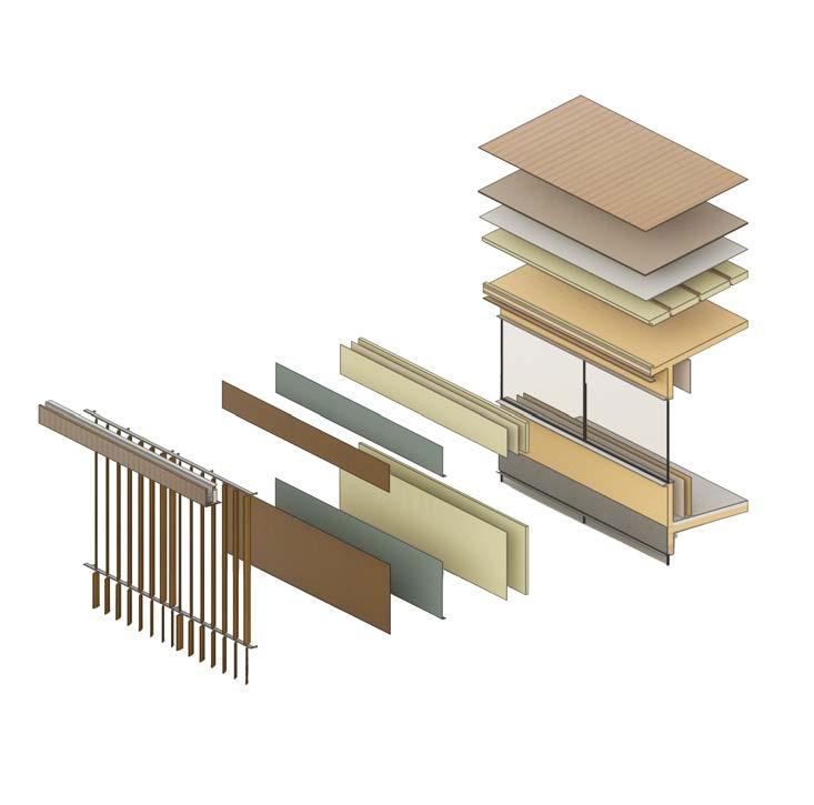
CLT PANELS + GLULAM COLUMNS
loadbearing structure
ROOF
structure
BEAMS Primary structure
CLT PANELS
structure
floor TRIPLE GLAZED PANELS Secondary structure TIMBER PANELS Secondary structure COPPER FINS - CLADDING Secondary structure CONCRETE PILE FOUNDATIONS Primary structure CLT panels joints Wall to foundation fixing 10 mm Copper Cladding 15mm + 850mm Fiberglass insulation 5mm Damp proof/vapour membrane 150mm CLT Panel 20mm Cavity 15mm Fireproof Plasterboard 20mm Acoustic Timber Panel 50mm x 40mm Painted Aluminium Frame 14mm Triple Glazed Window Panels External Windowsill Aluminium Finish Internal Windowsill GUTTER DETAIL Copper louvres mounted on suspended steel structure 90mm Air Cavity 10mm Windtight Breathable Roofing Membrane 10mm Vapour Barrier 160mm x 60mm Timber Battens 15mm Fireproof Plasterboard Lining 10mm Copper Roof Cladding 5mm Bitominous Sheeting 25mm Timber Roof Board 150mm CLT Panel 80mm + 80mm Fiberglass Rigid Insulation Steel fixture for facade structure and lintel 1. 10mm Copper cladding 2. 140mm U-profiled steel gutter 3. Flat bar + ankled bar + steel bolt 4. 40mm x 40mm RHS stainless steel 5. 80mm + 80mm Rigid fiberglass insulation 6. 80mm x 20mm timber battens 7. 10mm Folded copper cladding finish 3500mm 6000mm 6000mm 6000mm 8000mm 6000mm 6000mm 6000mm 8000mm 8000mm 6000mm
Primary
COPPER
Secondary
GLULAM
PREFABRICATED
Primary
-
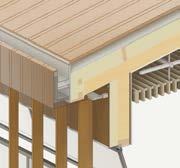
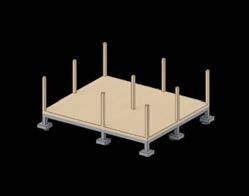
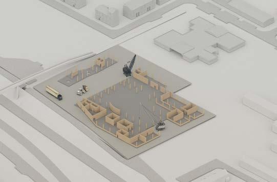
CONSTRUCTION SEQUENCE
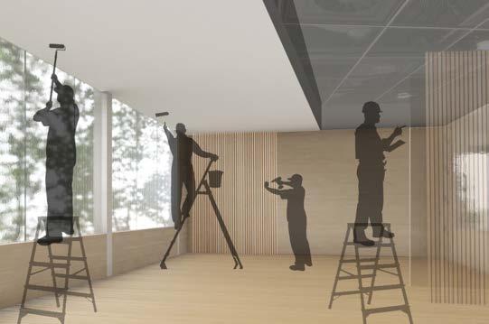
11. Services montage + internal finishes. At this stage this involves installation of plumbing, electrical, and HVAC (heating, ventilation, and air conditioning) services within the building structure, considering design requirements.
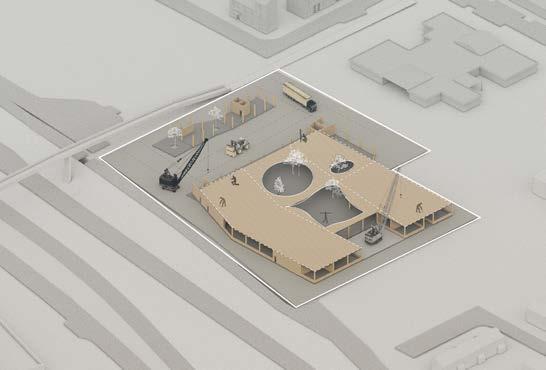
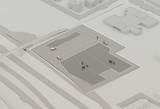
12. Once the building construction is finishes paving and access routes are made. After that landscape is arranged; planting greenery with involvement of local community.
13. Possible repurposing of structure and recycling of materials in future - thanks to the open, multipurposal layout building reuse is prioritised.
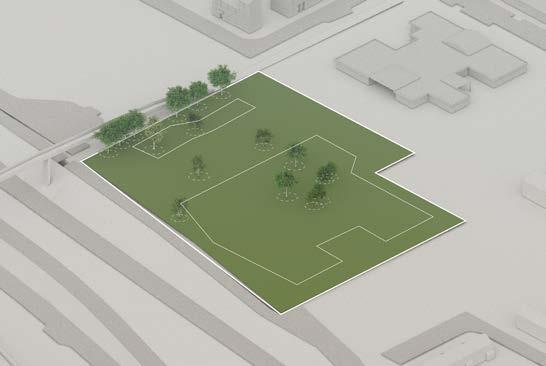
 2. Removing the existing greenery (which will be plant later. in the final construction stages).
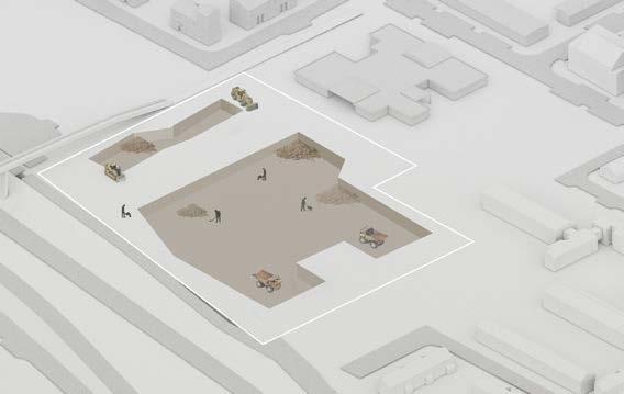
3. Clearing the site and site preparations; excavation of soil, levelling the ground and installing utilities.
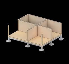
4. Casting concrete foundations.
5. Transport of CLT panels and glulam columns. During construction proper storage of timber muss be considered to prevent from weather damage.
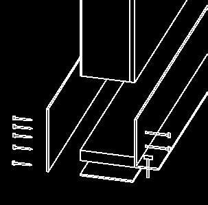
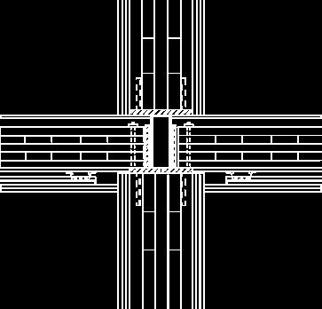
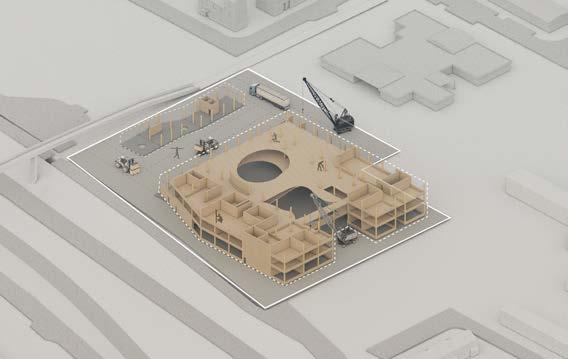
7. Floor assembly - standarasied and prefabriated CLT panels are mounted.The connection sbetween wall and floor panels are reinforced through steel joints.
8. Further construction of upper floors; placing floor and wall panels in designated location using cranes and mounting them through specialized steel joinery.
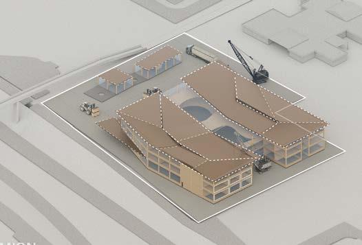
9. Roof construction; simultanously secondary structure - glazing and partition walls are mounted.
10. Facade assembly; suspended faacde structure is constructed and coper panels are fixed.
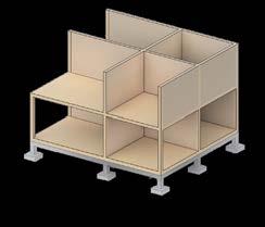
6. Assembly of main loadbearing components; CLT walls and glulam timber columns. This involves lifting and placing the panels in their designated positions using cranes or other lifting equipment and connecting the panels together using specialized connectors, such as screws, bolts, or adhesives
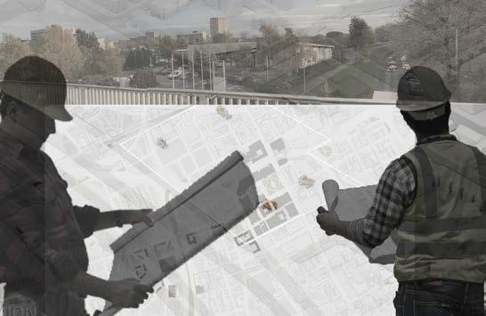
1. Strategic planning; consideration of site, context, residents and sustainability; amalysis of building lifecycle cost and environmental and economical impact.
2. Removing the existing greenery (which will be plant later. in the final construction stages).
3. Clearing the site and site preparations; excavation of soil, levelling the ground and installing utilities.
4. Casting concrete foundations.
5. Transport of CLT panels and glulam columns. During construction proper storage of timber muss be considered to prevent from weather damage.
7. Floor assembly - standarasied and prefabriated CLT panels are mounted.The connection sbetween wall and floor panels are reinforced through steel joints.
8. Further construction of upper floors; placing floor and wall panels in designated location using cranes and mounting them through specialized steel joinery.
9. Roof construction; simultanously secondary structure - glazing and partition walls are mounted.
10. Facade assembly; suspended faacde structure is constructed and coper panels are fixed.
6. Assembly of main loadbearing components; CLT walls and glulam timber columns. This involves lifting and placing the panels in their designated positions using cranes or other lifting equipment and connecting the panels together using specialized connectors, such as screws, bolts, or adhesives
1. Strategic planning; consideration of site, context, residents and sustainability; amalysis of building lifecycle cost and environmental and economical impact.
FACADE + WALL STRUCTURE
1. 10 mm Copper Cladding
2. 15mm + 850mm Fiberglass insulation
3.5mm Damp proof/vapour membrane
4. 150mm CLT Panel
5. 20mm Cavity
6. 15mm Fireproof Plasterboard
10 mm Copper Cladding
15mm + 850mm Fiberglass insulation
5mm Damp proof/vapour membrane
15mm Internal Floor Lining
65mm Concrete Floor Topping
25mm wood board
150mm CLT Floor Panel
10mm breathable membrane
150mm CLT Panel
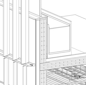
SUSPENDED FACADE FIXTURES DETAIL
20mm Acoustic Timber Panel
20mm Cavity 15mm Fireproof Plasterboard
15mm Fireproof Plasterboard
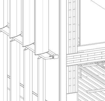
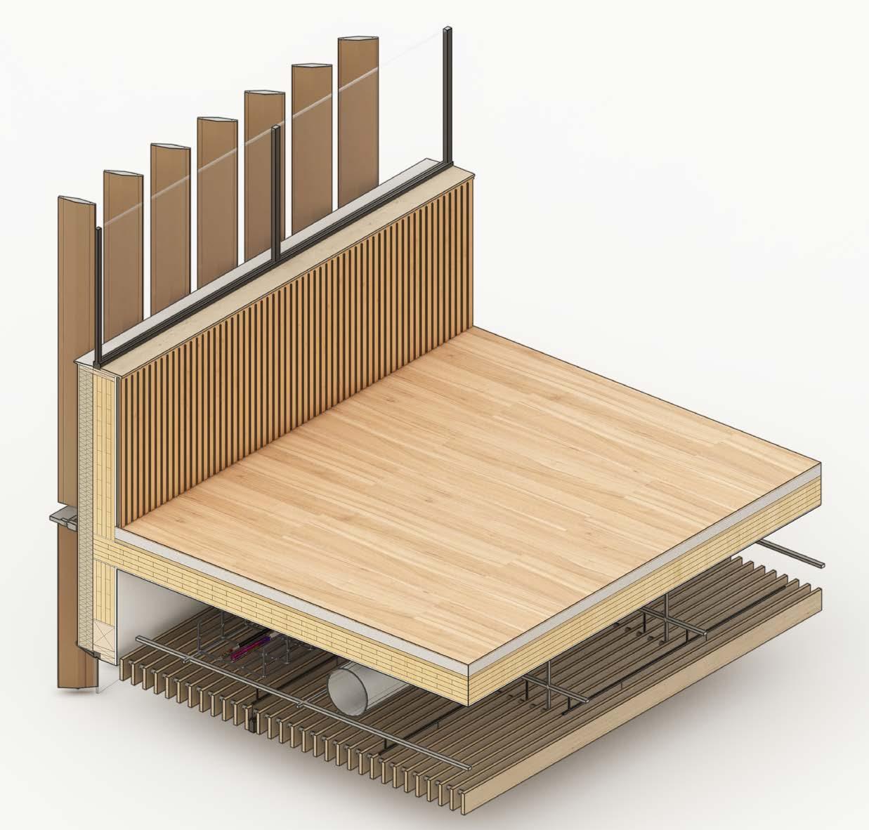
CEILING VOID - SERVICES
1. 30mm x 30mm Unistrut Grid System for suspended ceiling (800mm x 800mm)
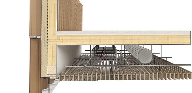
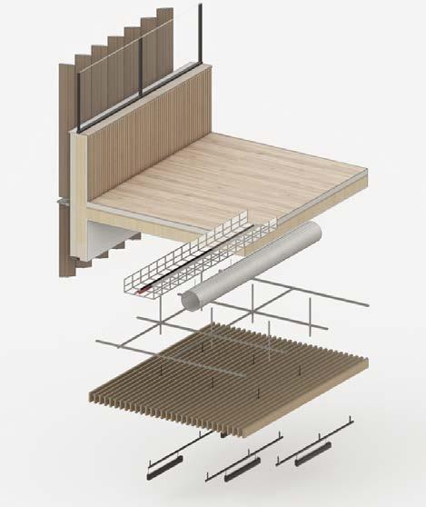
2. 25mm x 100mm Timber Panels
3. 25mm Aluminium Dowels
4. 90mm x 50mm Lighting fixtures
5. 200mm radius Ventilation Shaft
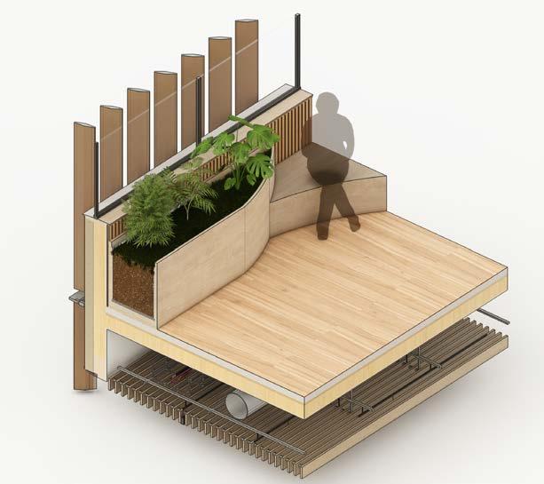
PLANTERS & SEATING
7. 20mm Acoustic Timber Panel
8. 50mm x 40mm Aluminium Frame sealed
9. 14mm Triple Glazed Window Panels
10. External Windowsill Aluminium Finish
11. 100mm x 25 mm timber batten
12. Internal Windowsill
13. 40mm x 150mm timber wood support
1:5 TACTILE DETAIL WALL BUILD UP FLOOR BUILD UP
350mm 550mm 150mm 150mm Services void Services void Timber panels + lights fixtures Floor slab
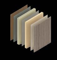
MATERIAL SELECTION
(FACADE PANELS)

sustainability + internal comfort
PLASTERBOARD


Copper cladding offers sustainability through its durability, recyclability, and low maintenance requirements. Its natural antimicrobial properties contribute to healthier indoor environments while minimizing waste and the need for frequent replacements.
Plasterboard offers several benefits, including its versatility and ease of installation. It can be easily cut and shaped to fit various architectural designs, allowing for flexibility in interior construction. Additionally, plasterboard provides excellent fire resistance properties, contributing to the overall safety of buildings.


CLT embodies sustainability through its renewable nature and carbon sequestration capabilities. As a wood product, CLT reduces carbon emissions associated with construction and promotes sustainable forest management practices, making it an environmentally-friendly choice for building materials.

Acoustic timber panels provide dual benefits of enhancing the aesthetics of interior spaces while improving sound insulation. They add a natural and warm visual appeal, help to reduce noise levels and create a more pleasant acoustic environment.


Glulam, demonstrates sustainability through its renewable source and energy-efficient production process. Glulam offers a durable and versatile structural solution with a low carbon footprint, contributing to sustainable construction practices.
Painted timber surfaces are easy to clean and maintain, making them a practical choice for high-traffic areas while retaining the natural warmth and beauty of the wood.


Use of concrete is reduced to the necessary elements - foundations and floor topping. Besides its high carbon foorprint it offers a high durability and low maintenance, which supports structural resilience.

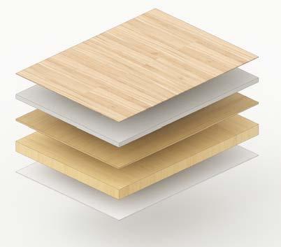
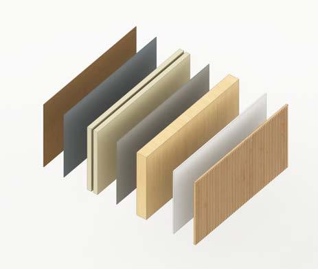
WALL BUILD UP FLOOR BUILD UP
ACOUSTICS
Acoustics was an important design consideration due to the requirements of study areas and classrooms. To provide better acoustic conditions triple glazed panels would be used to reduce noise from the adjacent highway. Meanwhile, in the interior, timber panels would be aplied.

COPPER CLT GLULAM CONCRETE
ACOUSTIC TIMBER
PAINTED TIMBER (RECYCLED MATERIAL)
PANELS
15mm Internal Floor Lining 65mm Concrete Floor Topping 25mm wood board 150mm CLT Floor Panel 15mm Fireproof Plasterboard
Cladding
20mm
Plasterboard
10 mm Copper
15mm + 850mm Fiberglass insulation 5mm Damp proof/ vapour membrane 150mm CLT Panel
Cavity 15mm Fireproof
20mm Acoustic Timber Panel 10mm breathable membrane
20mm Acoustic Timber Panel
SECTION 1:20
ROOF DETAIL
1. 10mm Copper cladding
2. 140mm U-profiled steel gutter


3. Flat bar + ankled bar + steel bolt

4. 40mm x 40mm RHS stainless steel
5. 80mm + 80mm Rigid fiberglass insulation
6. 80mm x 20mm timber battens

7. 10mm Folded copper cladding finish
WALL & SLAB CONNECTION
1. 10 mm Copper Cladding
2. 15mm + 850mm Fiberglass insulation
3.5mm Damp proof/vapour membrane
4. 150mm CLT Panel
5. 20mm Cavity
6. 15mm Fireproof Plasterboard
7. 20mm Acoustic Timber Panel

8. 50mm x 40mm Aluminium
Frame sealed
9. 14mm Triple Glazed Window Panels
10. External Windowsill Aluminium
Finish
11. 100mm x 25 mm timber batten
12. Internal Windowsill

13. 40mm x 150mm timber wood support
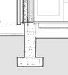
FOUNDATION
DETAIL
1. 15mm Internal Floor Lining
2. 65mm Concrete Floor Topping
3. 10mm Damproof Membrane

4. 25mm Concrete Floor Topping
5. 150mm + 325mm Concrete
Foundation
6. 1000mm x 400 mm Concrete
Cap with reinforcements
FIRE EMERGENCY REGULATIONS
Due to the mass timber structure, the project required thorough consideration of fire emergency regulations. Following the consultation with fire engineer, the fire sprinklers system would be installed within each 10m to prevent the structure from fire spread.


FIRE SPRINKLERS SYSTEM
Estimated position of fire sprinkler.
WEHICLE ACCESS
To maximise the safety, the vehicle access to more than 50% of the building perimeter will be provided.


MATERIALITY
COPPER CLADDING
FIRE RESISTANT PLASTERBOARD - INTERNAL FINISH

The internal mass structure will require coverage with fire resistant plasterboard to reduce the risk of fire spread.


Furthermore, to reduce the combustability of external wall the copper panels and painted still cladding will be applied, instead of timber.
EVACUATION ROUTES
Evacuation routes rely on two, closed staircases located in both ‘wings’ of the main structure.
BUILDING REGULATIONS
Responding to building regulations, fire safety regulations and accessibility issues to provide safe, comfortable and inclusive design.
FIRE ESCAPE ROUTES - UPPER FLOORS
FIRE ESCAPE ROUTES - GROUND FLOOR PLAN


RAMPS - ACCESS FOR DISABLED

Separated, enclosed fire escape staircases located inthe two wings of structure.
In compliance with Fire and Safety Regulations, the building must have adequate means of escape leading to a secure location. The project addresses this requirement by offering an ample number of escape routes. In addition to the main staircase, two fire escape staircases are strategically positioned in opposite wings of the building. This distribution ensures that, in the event of a fire, movement is evenly dispersed toward different exit points, preventing overcrowding at the primary exit.
FIRE ESCAPES STAIRCASE
Following the guidelines outlined in document K, the ramp is situated in a prominently visible area and adheres to the recommended incline specifications of building regulations. The width of the ramp does not exceed 18m (13m), and the slope ratio ensures a comfortable incline (ratio<1:16), offering ample space for wheelchair maneuverability. Additionally, the presence of 1000mm handrails ensures safety measures are in place.

Fire escape staircases are strategically placed away from the main circulation route, adhering to Fire and Safety Regulations. The enclosing walls serve as a protective measure to prevent the dissemination of smoke and fire.
ACCESS - SAFETY
The primary staircase complies with the requirements outlined in the building regulations. The width of the staircase flight offers ample space, measuring 1900mm (minimum 1250mm). The length of the landings (2500mm) surpasses the width of the steps (1900mm), providing areas for resting and socializing. Larger landings are incorporated after every 6 steps, offering space for informal gatherings and accommodating individuals with walking disabilities. To accommodate the width of the staircase (exceeding 2000mm), an additional railing has been installed in the middle of the flight. Railings meet required height providing safety for users.

ACCESSIBILITY


The project endeavors to establish accessible and user-friendly access routes for all individuals, in alignment with the Access to and Use of Building Regulations (Document M, Volume 2, Buildings other than dwellings).
With these factors in mind, the main entrance is designated for pedestrians, while vehicles and cyclists are directed to utilize the secondary access route. To minimize the risk of accidents, there is a distinct separation between the bicycle path and the vehicle path. Furthermore, the car park incorporates several designated spaces for wheelchair users and offers a nearby access pathway to the building entrance.
900mm 900mm 1000mm 135000 mm Landing 2000mm clear space
Minimal landing width is equal to step’s width. 2100mm 400mm 2400mm 9000mm 150mm MAIN STAIRCASE DESIGN 3900mm 1900mm 1900mm 450mm 2500mm 2100mm
PARKING BAY FOR DISABLED PEOPLE BICYCLE PATH VEHICLE WAY CAR PARKING ROUTE TO SECONDARY ENTRANCE DESIGNATED PATH FROM CAR PARKING BICYCLE STORAGE 1200mm 4800mm 6000mm
2000mmclearspace 1500mm minimum width 3000mm
1000mm Railing 900mm-1000mm GROUND FLOOR LEVEL LOWER FLOOR LEVEL FIRST FLOOR LEVEL SECOND FLOOR LEVEL 1250mm 2750mm
+ RAILINGS
Main entrance
1000mm 800mm
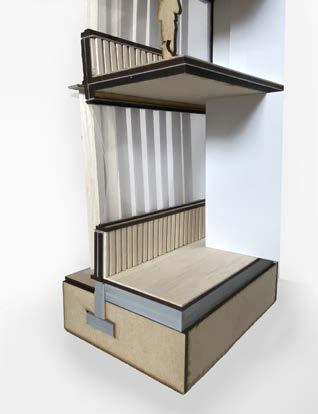
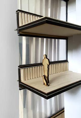
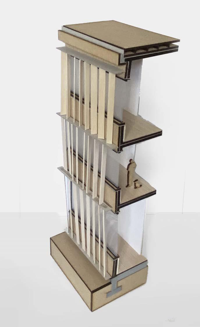
PHYSICAL MODEL
SCALE 1:25
Physical modeldemonstration of internal and external qualities of chosen part of south facade. The modelmaking process became a way of exploration of materiality features as well as structural integrity.
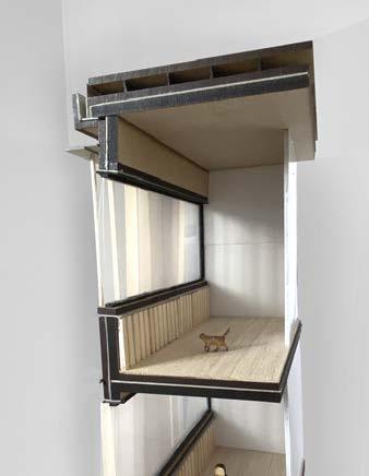
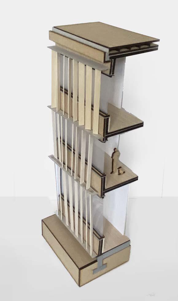
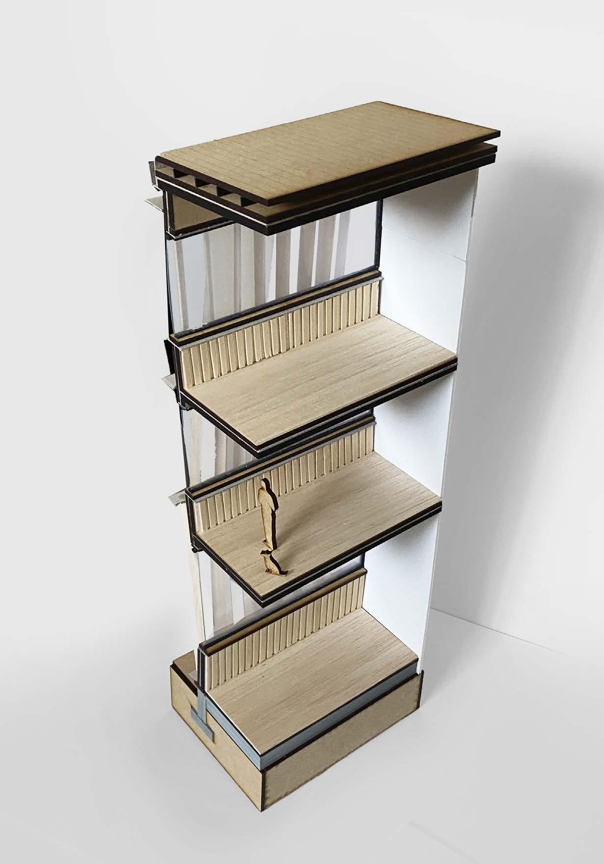 Parametric facade detail
Second floor detailinternal light quality
Foundation detail
First floor - acoustic panels + materiality
Plan context
Parametric facade detail
Second floor detailinternal light quality
Foundation detail
First floor - acoustic panels + materiality
Plan context
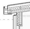
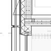
SECTION 1:20 ROOF DETAIL WALL & SLAB CONNECTION FOUNDATION DETAIL 10mm Copper cladding 140mm U-profiled steel gutter Flat bar + ankled bar + steel bolt 40mm 40mm RHS stainless steel 80mm 80mm Rigid fiberglass insulation 80mm 20mm timber battens 10mm Folded copper cladding finish 10 mm Painted Aluminium Cladding 15mm 850mm Fiberglass insulation 3.5mm Damp proof/vapour membrane 150mm CLT Panel 20mm Cavity 15mm Fireproof Plasterboard 20mm Acoustic Timber Panel 50mm 40mm Aluminium Frame sealed 14mm Triple Glazed Window Panels 10. External Windowsill Aluminium Finish 11. 100mm 25 mm timber batten 12. Internal Windowsill 13. 40mm 150mm timber wood support Concrete floor Concrete pile foundation Concrete floor topping 15mm Internal Floor Lining 65mm Floor Topping 25mm 15mm CLT Floor Panel 15mm Fireproof Plasterboard 150mm 150mm Timber Beam 150mm 40mm Timber Batten 100mm 30mm Timber Board 15mm Fireproof Plasterboard
EXHIBITION OUTPUTS
REFLECTIONS
ATELIER’S POSITION
Developing a project in CPU atelier enabled me to explore and understand complex systems of connections that bond individual structrures into a multilevel, organism of mutual links. Developing project with consideration of its wider economical, social and environmental impact widened my perception of architecture’s role in human life. Furthermore, atelier’s aim to utilise digital tools and new technologies encouraged me to experiment with design form to find the most efficient design solutions.
BIOPHILIC DESIGN AND SUSTAINABILITY

Prioritizing environmental design impacted significantly project, dictating its form, materiality and facade design. Being a part of CPU atelier I learnt the importance of passive energy solutions and how to aply them to the project for the effective performance. Moreover, while incorporating various strategies into building and testing different outcomes I have learnt how each, small decision can impact the environment on a major level. Thus I acknowledged the responsibility of architect’s role in shaing future, sustainable cities.
TECHNOLOGY
The development of tactile detail was a challenging, yet very enriching task, as it showed me the complexity that stands behind architectural elements. It contributed to broadening my knowledge about construction materials, tools and processes, as well as encouraged me to consider innovative structural strategies, which I tried to implement in the project.
SOCIAL, ECONOMICAL AND CULTURAL CONTEXT
Humanities lectures remarkably affected my attitude towards architecture, as I could learn about different ways of perceiving and creating architecture. Studying texts from various architects and theorists made me question the rooted schemes of architectural design. Moreover, I have learned about the importance of vernacular architecture and natural architetcure, which impacted the design process of the project, making it more human-centred and community based.
SYNTHESIS
Engawa aims to synthesise afforementioned aspect in a cohesive, engaging manner, The design drivers - sustainability, connectivity and biophilic, user-centred design - designated design path on each stage, resulted in a structure that prioritises ecology, users, local context and regeneration of the area. The values that I learned throughout the design process will significantly impact my further architectural journey, where I will try to implement the approach and knowledge gained during Studio 3.2.
APPENDIX
FINAL PLAN
1. Atrium
2. Lounge
3. Meeting rooms
4. Classrooms
5. Group study area
6. Quiet study area
7. Group study rooms
8. Kitchen for students
9. Toilets
10. Storage
SECOND FLOOR 1 2 2 3 3 4 4 5 6 7 7 8 9 10 11 0 5 10 5
11. Adjustable working/learning area
