Industrial Water and Process Solutions MAXIMIZE ASSET VALUE THROUGH SUPERIOR SERVICE AND SPECIALTY CHEMICAL EXPERTISEhalliburton.com September 2022


www.mercuryadsorbents.com Optimized Mercury Removal With MERSORB® mercury adsorbent pellets MERSORB® mercury adsorbent pellets – a Trademark of Nucon International, Inc. (NUCON®) • PROVEN RELIABLE – EVEN IN CRACKED GAS • HIGH MERCURY CAPACITY – HOT, COLD, WET or DRY • MORE PELLET SIZES – MORE PROCESS DESIGN FLEXIBILITY • LOW MOISTURE – FAST START-UP • 40 YEARS EXPERIENCE – ADSORPTION PROCESS DESIGN Your Experts for Mercury Removal – in Ethylene Plants PROVEN PROCESS – PROVEN PRODUCTS AntiMercure® is a Registered Trademark of Selective Adsorption Associates, Inc. for its Process Engineering Services MERSORB® is a Registered Trademark of NUCON International, Inc. for its mercury adsorbent pallets • Cracked Gas • Ethane Feed Gas • LPG, Naphtha, & Light Condensate Feed Liquid • Regen. Gas from Cracked Gas Driers • Light Olefin Gas from FCC Units • AntiMercure® Process Engineering • MERSORB® mercury adsorbent pellets

CBP006075
MOFs for the energy transition
Improving level reliability Tai Piazza, VEGA Americas Inc., USA, discusses the use of gamma instrumentation to improve level reliability in the delayed coking unit.
Precious metals for green chemistry Gisa Meissner and Konrad Krois, Heraeus Deutschland GmbH & Co. KG, Germany, discuss the use of precious metal-based catalysts for the efficient conversion of 5-hydroxymethyl furfural (5-HMF) into 2,5-diformylfuran (DFF) to produce phenolic resins.
E. M. Ishiyama, J. Kennedy, S. J. Pugh and H. U. Zettler, Heat Transfer Research Inc., explore how successful digital transformation is helping ENEOS Group refineries in Japan to eliminate waste, reduce lost time in data processing, and facilitate collaboration between different work groups within the organisation.
COVERFRONTMONTH'STHIS
A new direction for cybersecurity
Fouling management through digital transformation
Jim Crowley, Industrial Defender, USA, outlines the importance of cybersecurity in the oil and gas industry, and provides a step-by-step guide to cultivating a more cyber-aware business.

From molecular-level engineering to enhanced aromatics economics Roy van den Berg and Richard Mauer, Shell Catalysts & Technologies, discuss how an innovative zeolite technology is unlocking business value. 22
CONTENTS September 2022 Volume 27 Number 09 ISSN 1468-9340 Hydrocarbon Engineering Like Join Hydrocarbon Engineering @HydrocarbonEng Follow CONVERSATIONJOIN THE

A deep dive into DRL Gadi Briskman, Modcon Systems, UK, explains how to safely deploy Deep Reinforcement Learning (DRL) for process control, via integration with online analysers.
Athlon, a Halliburton Service, provides industrial water and process treatment solutions to refinery, petrochemical, ammonia/fertilizer, and heavy industrial operations. Through onsite technical service and engineering support, Athlon helps customers with their business goals, including improving reliability, increasing throughput, and enhancing the efficiency and flexibility of operating units.
Dr. M. Asunción Molina Esquinas, Instituto de Catálisis y Petroleoquímica, and Dr. Meritxell Vila, MERYT Catalysts & Innovation, explain why metal-organic frameworks (MOFs) have an essential role to play in helping the energy sector to achieve its energy transition and independence goals.
Copyright© Palladian Publications Ltd 2022. All rights reserved. No part of this publication may be reproduced, stored in a retrieval system, or transmitted in any form or by any means, electronic, mechanical, photocopying, recording or otherwise, without the prior permission of the copyright owner. All views expressed in this journal are those of the respective contributors and are not necessarily the opinions of the publisher, neither do the publishers endorse any of the claims made in the articles or the advertisements. Printed in the UK.
45 Meet the heat Edward Cass, Paratherm Heat Transfer Fluids, USA, details the use of thermal fluid systems technology for the process heating industries.
64
Keeping up with the times If pestilence were not bad enough, North America’s downstream sector has war, climate change and shortages to deal with. Gordon Cope, Contributing Editor, details how the oil and gas industry is faring in the face of these challenges.
38
69
Circulations
Guest comment 05 World news 10
03
The critical link for digitalisation Jason Apps, ARMS Reliability, Australia, discusses how Asset Strategy Management is key to the successful digital transformation of the downstream oil and gas sector.
Stepping stones on the path to sustainability Lucas Vergara, Axens, France, presents catalytic solutions to help tackle the challenges associated with co-processing sustainable feeds. 29
15
33
2022 Member of ABC Audit Bureau of


51
57
TOFROMTAKE-OFF.AMBITIONACTION.
SAF reduces CO2 emissions by at least 85% when compared to conventional fuel. And we have the proven technologies to make it all happen. Now. Turn your sustainable ambitions into a sustainable business. Join Flight Plan Green. Find out how: topsoe.com/saf
Ramp up production of sustainable aviation fuel. Together we can transform the aviation industry’s carbon intensity for the better. Keep planes in the air, and still be on track to zero.
GREENPLANFLIGHT
The EPA’s RMP proposal is expected to single out HF alkylation at fuel refineries, and saddle facilities with an expensive, unconstructive new paperwork burden. Regulators know full well that requiring alternative alkylation technology assessments at refineries that are already up and running will consume valuable man hours, impose significant costs, and yield nothing in terms of actionable results or safety improvements. The point is simply to put a barrier in the way of HF alkylation. This is precisely what some anti-refining groups are lobbying for.
GEOFF MOODY SENIOR VICE PRESIDENT, GOVERNMENT AND POLICY, AMERICAN FUEL & PETROCHEMICAL MANUFACTURERS (AFPM)

A loss or major reduction in HF alkylation would have devastating consequences for US and global fuel supplies and for affordable energy advocates everywhere. Most policymakers have no idea that those are the stakes with the RMP.Nearly half of the alkylate produced in the US is made with HF catalyst. Refineries with HF alkylation units account for nearly 40% of US fuel manufacturing. Facilities cannot seamlessly transition from one alkylation technology to another. It is a massive undertaking that could approach US$1 billion – a cost so extreme that it could push some refineries to close. Even if a transition was feasible, safety would not be better served. Alkylation risk would simply be shifted to other parts of the supplyThosechain.who oppose HF alkylation wrongly believe that allowing use of this technology means compromising on safety. Refiners do not accept that. We have done more than any other industry to formalise and evolve HF safety guidelines, such as through API Recommended Practice 751. Our safety procedures are consistently reviewed and enhanced every few years as we gather intel from real-world experiences and capitalise on advancements made in risk-reducing technologies. Because of all the steps that refiners take to keep employees and community neighbours safe, HF alkylation units pose less life-threatening risk to their local public than vehicle collisions, lightning strikes and sharp objects, just to name a few. When refiners say safety is our priority, we meanEPAit. regulations must reflect how thoroughly HF is managed by US refiners. Policy that incorrectly presumes the opposite could put in jeopardy significant US fuel manufacturing, and our ability to produce the cleanest possible gasoline and aviation fuels in the US. The effect for consumers would be tighter fuel supplies and potentially higher prices. There is no way that could be considered a win by the Biden team.
GUEST COM MENT September 2022HYDROCARBON ENGINEERING 3
EPA regulations must reflect how thoroughly HF is managed by US refiners. Policy that incorrectly presumes the opposite could put in jeopardy significant US fuel manufacturing.
F or years, the US Environmental Protection Agency (EPA) has overseen a regulation known as the Risk Management Plan (RMP). The RMP is a safety performance standard that applies to fuel refineries and a litany of other US manufacturers that use high volumes of certain chemicals. RMP sites are expected to make continuous investments and improvements in safety performance, which is a good thing. Refiners fall under RMP jurisdiction for several chemicals, two of which are catalysts that facilities use to produce alkylate – an irreplaceable component in the cleanest US gasoline and high-octane aviation gas. It is because of alkylate and the EPA’s upcoming proposal to change the RMP that the Biden administration might soon find itself making an unforced energy error. The two primary and commercially-proven catalysts that refiners use to produce alkylate are hydrofluoric acid (HF) and sulfuric acid. Both are on the RMP list, but HF tends to draw more attention and is the focus of major refinery safety investments, training, and risk mitigationRefinerstechnology.accountfor less than 2% of global HF consumption. HF is near ubiquitous in manufacturing.large-scaleItisused in agriculture and also to produce computer chips, refrigerants, hydrogen fuel cells, pharmaceuticals, branded aluminium cans, and even drinking water. Even still, HF in fuel manufacturing draws a disproportionate share of regulatory interest.
FFCs slurry oils sell for just a few hundred dollars/ton, but when converted into Carbon Black – a key component in high-end plastics, tire manufacturing, and other rubber-based components – they can reach a market price of $2,500 USD/ton. ET Black™: the industry technology of choice Eurotecnica’s modified furnace black process, ET Black™, efficiently converts slurry oils into a wide range of carbon black grades, giving you access to an exciting and fast-growing industry. With guaranteed operating flexibility and reliability, easy maintenance, and a low CAPEX, ET Black™ has become the technology of choice for industry leaders like ADNOC Refining. Contact us at www.igoforETBLACK.com to find out more.


ulzer Chemtech and BASF have signed a Memorandum of Understanding (MoU) with the goal of advancing technologies for renewable fuels and chemically-recycled plastics that will further expand the partners’ portfolio of sustainable solutions. The companies have entered into a strategic partnership to reduce the carbon intensity of renewable diesel and sustainable aviation fuel, and drive the development of innovative, cost-effective chemical processing solutions to improve the conversion of plastic waste into new plastics. The collaboration integrates Sulzer Chemtech’s capabilities in licensed processing technologies and mass transfer equipment with BASF’s high-performance adsorbents and catalysts.Sulzer Chemtech is leading efforts to harness greener resources that can help global producers to achieve net zero ambitions. BASF Process Catalysts is driving multiple initiatives aimed at turning plastic waste into a secondary raw material, e.g. with its PuriCycle® portfolio, as well as providing adsorbent and catalytic materials to produce clean and renewable fuels.
September 2022HYDROCARBON ENGINEERING 5 WORLD NEWS Europe | Woodside and Uniper sign agreement for LNG supply Woodside Energy Trading Singapore Pte Ltd has entered into a flexible long-term sale and purchase agreement (SPA) with Uniper Global Commodities SE (Uniper) for Woodside to supply LNG from its global portfolio into Europe, including Germany, for a term up to 2039, commencing in January 2023. The quantity of LNG to be supplied is up to 12 cargoes per year (equivalent to more than 0.8 million tpy or 1 billion m3 of natural gas). Supply from September 2031 is conditional upon Uniper finalising its long-term strategic capacity bookings in Northwest Europe, expected by MarchWoodside2023.
Three new petrochemical crackers have come online to support growth in domestic ethylene production: two in Texas and one in Pennsylvania.
Energy CEO, Meg O’Neill, said: “Woodside is pleased that this latest agreement with Uniper will provide a new source of LNG for consumers in Europe who are seeking alternatives to Russian gas. It also reflects the increasingly interconnected nature of LNG trade in the Atlantic and Pacific basins as global markets respond to energy security challenges.”
It is forecast that US exports of ethane will continue to grow from around 350 000 bpd in 2Q22 to approximately 440 000 bpd in 4Q22. Ethane exports are expected to rise to 460 000 bpd in 2023.
USA | EIA expects US ethane production to grow by 9% in 2H22
In the EIA’s long-term ‘Annual Energy Outlook 2022’, the rapid growth in US ethane production is expected to plateau at around 2.7 million bpd in the second half of this decade.
Global | Sulzer and BASF ink MoU S
USA | BP to sell its interest in the BP-Husky Toledo refinery B P has reached an agreement to sell its 50% interest in the BP-Husky Toledo refinery in Ohio, US, to Canada-based Cenovus, its joint venture (JV) partner in the facility. Under the terms of the deal, Cenovus will pay US$300 million for BP’s stake in the refinery, as well as the value of inventory, and take over operations when the transaction closes, which is expected to occur later in 2022. BP and Cenovus will also enter into a multi-year product supply agreement. The BP-operated refinery has been an important part of the region’s economy for more than 100 years, supporting jobs and safely supplying gasoline, diesel and other essential fuels andAfterproducts.divesting its stake in the BP-Husky Toledo refinery, BP’s refining portfolio will reduce from three to two facilities.
E thane production has been increasing in the US for the past five years, and it reached a monthly record of 2.5 million bpd in March 2022. More than 2.4 million bpd of ethane has been produced in the US every month since then. In the EIA’s ‘Short-Term Energy Outlook’ (STEO), ethane production in 2H22 is forecast to grow by 9% compared with 1H22, averaging over 2.6 million bpd. It is expected that production in 2022 will exceed production in 2021 by 16%, or 340 000 bpd. The STEO forecasts annual US ethane production will increase by 7% during 2023 to nearly 2.7 million bpd, supporting continued growth in US consumption and exports.

Steve Hill, Executive Vice President Energy Marketing Shell, stated: “We are very happy to be working once again with Energy Transfer and adding Lake Charles volumes to our global LNG supply portfolio.”
IN BRIEF
WORLD NEWS September 2022 HYDROCARBON ENGINEERING 6
The award follows the successful completion of the pre-FEED activity and encompasses early engineering and procurement services to support the project schedule. Under the contract scope, McDermott will provide FEED services for a new modularised production unit. The unit will produce ultra-low-sulfur gasoline with up to 10 ppm sulfur, to meet the proposed changes to Australia’s fuel quality standards from the end of 2024. Lower sulfur gasoline will support improved vehicle emissions. Work on the project will be executed from McDermott’s engineering centre in the Hague, the Netherlands, with support from its offices in Gurgaon, India, and Perth, Australia.
B ASF, SABIC and Linde have started construction of one of the world’s first demonstration plants for large-scale electrically-heated steam cracker furnaces. By using electricity from renewable sources instead of natural gas, the new technology has the potential to reduce carbon dioxide (CO2) emissions by at least 90% compared to technologies commonly usedThetoday.demonstration plant will be fully integrated into one of the existing steam crackers at BASF’s Verbund site in Ludwigshafen, Germany. It will test two different heating concepts, processing around 4 tph of hydrocarbon, and consuming 6 MW of renewable energy. Start-up is targeted for 2023. BASF and SABIC are investing into the project, and the plant will be operated by BASF. Linde is the engineering, procurement and construction partner for the project, and in the future will commercialise the developed technologies.
Australia | McDermott awarded FEED contract from Viva Energy Australia M cDermott International has been awarded a front-end engineering design (FEED) contract from Viva Energy Australia, as part of its Geelong Refinery project, to provide additional desulfurisation capabilities.

Germany | BASF, SABIC and Linde to construct demonstration plant
singapore INEOS Phenol has announced that it has agreed to acquire the entire asset base of Mitsui Phenols Singapore Ltd from Mitsui Chemical. The business produces over 1 million tpy of product, including cumene (410 000 tpy), phenol (310 000 tpy), acetone (185 000 tpy), bisphenol A (150 000 tpy), and alpha-methylstyrene (20 000 tpy). usa Baker Hughes has announced an agreement to acquire Quest Integrity, a subsidiary of Team Inc. The acquisition is expected to close in 4Q22 and will be integrated into the Process & Pipeline Services product line within Baker Hughes’ Digital Solutions segment. south korea Axens and Hyundai Chemical Co. have successfully achieved the start-up of the pyrolysis gasoline (Pygas) unit – part of the Hyundai Chemical petrochemical grassroots complex in Daesan, South Korea. usa Orbital Infrastructure Group Inc. (OIG) and Mangan Inc. have entered into an asset purchase agreement under which Orbital will sell its Houston, Texas gas business, Orbital Gas Systems North America Inc. (Orbital NA) to Mangan. saudi arabia Aramco and SABIC have obtained the world’s first independent certifications recognising blue hydrogen and ammonia production. The certifications were granted by TÜV Rheinland to SABIC AN for 37 800 t of blue ammonia, and to Aramco’s wholly-owned refinery, SASREF, for 8075 t of blue hydrogen. To certify ammonia and hydrogen as blue, a significant part of the carbon dioxide (CO2) associated with the manufacturing process needs to be captured and utilised in downstream applications.
USA | Shell and Energy Transfer sign LNG SPA S hell NA LNG LLC and Energy Transfer LNG Export LLC have signed a 20-year LNG sale and purchase agreement (SPA) for the offtake of 2.1 million tpy of LNG from the Lake Charles LNG project in theTheUS.SPA will become fully effective upon the satisfaction of certain conditions, including Energy Transfer taking a final investment decision (FID). The facility will be constructed on the existing brownfield regasification facility site, and will capitalise on four existing LNG storage tanks, two deep water berths, and other LNG infrastructure. If sanctioned through an affirmative FID, the project will have a liquefaction capacity of 16.45 million tpy.
Want to co-process renewable feed? We want to contribute to a world that provides a viable future with enhanced quality of life for everyone. We do so by creating chemistry for our customers and by making the best use of available resources. To optimize our contribution to a sustainable future, BASF Refinery Catalysts is developing solutions to co-process renewable feed for your FCC operation! Oxygen to Carbon 0 0.1 0.2 0.3 0.4 0.5 0.6 0.7 0.8 0 0.5 1 1.5 2 2.5 Deoxygenation Required Ideal Manageable Challenging Transportation Fuels Light Olefins PE, PP Vegetable Oils Biomass Crude Oil Sustai n ability pihsrentraPnoitavonnIWesustainabilityenable Lower FootprintCarbon FeedstocksRenewableRecyclingReducingEmissions

Laurance Reid Gas Conditioning Conference Norman, Oklahoma, USA pacs.ou.edu/lrgcc
WORLD NEWS September 2022 HYDROCARBON ENGINEERING 8
DIARY DATES
Belgium | Wood to engineer olefin complex
31 October - 3 November 2022 ADIPEC Abu Dhabi, www.adipec.comUAE 7 - 10 November 2022 ERTC Berlin, www.worldrefiningassociation.com/event-events/ertcGermany 16 November 2022 Global Hydrogen Conference www.globalhydrogenreview.com/ghc22Virtual 29 November - 1 December 2022 Valve World Expo Düsseldorf, www.valveworldexpo.comGermany
The Hague, the www.events.crugroup.com/sulphurNetherlands 24 - 26 October 2022 RefComm Europe 2022 The Hague, the www.events.crugroup.com/refcommeuropeNetherlands 24 - 26 October 2022 8th Opportunity Crudes Conference Houston, Texas, www.opportunitycrudes.comUSA
The 56 000 Nm3/hr capacity hydrogen plant will utilise Technip Energies’ proprietary steam reforming technology to convert methane-rich offgas from the naphtha cracking process into hydrogen. The hydrogen plant will include a selective catalytic reduction (SCR) unit for control of NOx emissions. The new hydrogen unit will be integrated with LG Chem’s naphtha cracking complex (NCC) to allow LG Chem to convert the petrochemical pyrolysis complex to a more sustainable low-carbon process.
W ood has secured a new contract with INEOS in excess of US$100 million to deliver engineering, procurement and construction management (EPCm) services for Project One, a new petrochemicals complex in Antwerp, Belgium, which will deliver an ethane cracker with the lowest carbon footprint in Europe.Effective immediately, the four-year contract will be delivered by Wood’s Projects business unit. The scope is focused on the outside battery limit facilities for the ethane cracker and follows the successful completion of FEED for the facility.
USA | Commonwealth LNG and Woodside sign agreements
C ommonwealth LNG, a subsidiary of Commonwealth Projects, and Woodside Energy Trading Singapore Pte Ltd, a subsidiary of Woodside Energy Group Ltd, have announced the conversion of their non-binding heads of agreement (HOA) into two binding LNG sale and purchase agreements (SPAs).The SPAs are for the supply of up to 2.5 million tpy of LNG over 20 years from Commonwealth’s LNG export facility that is under development in Cameron Parish, Louisiana, US. Key terms in the HOA previously announced on 19 January 2022 remain unchanged in the binding SPAs, with first deliveries expected to commence in mid-2026.TheSPAs will become fully effective upon the satisfaction of customary conditions, including an affirmative final investment decision (FID) on the project.
T echnip Energies has announced that LG Chem has selected its proprietary blue hydrogen technology to supply its Daesan complex in SouthTheKorea.Blue H2 by T.ENTM hydrogen plant will capture a significant amount of carbon dioxide (CO2), and reduce carbon emissions from the petrochemical complex. LG Chem intends to utilise the captured CO2
South Korea | LG Chem selects Technip Energies’ blue hydrogen technology
Wood’s integrated project management team will also continue to oversee the project, working closely with the INEOS project team. Giuseppe Zuccaro, President of Process & Chemicals at Wood, said: “The chemicals sector, like all industries, is forging its own path to carbon neutrality. What Project One represents is the next era of ethylene production, a key component in most plastics. Through the combination of technology and an innovative technical design approach, it will be the most sustainable and energy-efficient steam cracker in Europe.”
The Woodlands, Texas, USA www.nistm.org 20 - 23 February 2023
10 - 13 October 2022 API Storage Tank Conference & Expo San Diego, California, www.API.org/storagetankUSA 18 - 20 October 2022 2022 AFPM Summit San Antonio, Texas, www.afpm.org/eventsUSA 24 - 26 October 2022 Sulphur + Sulphuric Acid Conference & Exhibition
6 - 7 December 2022 15th Annual National Aboveground Storage Tank Conference & Trade Show
Through multi-specialist integrated offers, we deliver ever more inventive and sustainable solutions to our industrial clients, always aiming at preserving the planet. www.axens.net
POWERING A SUSTAINABLEFUTURE

J ust as the spectre of COVID-19 recedes, other plagues bedevil the downstream sector: as demand kicks in with the summer driving season, motorists face epic gasoline and diesel prices. Several factors are contributing to the high prices but, ironically, a shortage of crude is not one of them. While other jurisdictions scramble to replace sanctioned Russian crude, North America is awash in oil. Oil output in western Canada rose from 3.9 million bpd in 2020 to 4.45 million bpd by the end of 2021. Canada now exports approximately 4 million bpd to the US, and that volume is expected to rise to 4.2 – 4.4 million bpd by 2026. Production from the Texas Permian basin has recovered to pre-COVID-19 levels; output of light, tight crude exceeded a
10September 2022 HYDROCARBON ENGINEERING

If pestilence were not bad enough, North America’s downstream sector has war, climate change and shortages to deal with. Gordon Cope, Contributing Editor, details how the oil and gas industry is faring in the face of these challenges.

September 202211
HYDROCARBON ENGINEERING record 5 million bpd in February 2022, and is expected to reach 5.6 million bpd by the end of 2022, before climbing to 6.5 million bpd in 2023.
The number one reason for high fuel prices is a shortage of capacity. Over the last two years, refiners in the US closed or suspended over 1 million bpd at ageing refineries. Currently, the US has approximately 18 million bpd capacity to produce gasoline, diesel and jet fuel, and the average refinery usage is standing at an impressive 95%. That leaves no wiggle room, however, and planned maintenance shutdowns have been postponed.
A major incentive for the high utilisation rate is surging crack spreads. Starting in the latter half of 2021, the refining profit per barrel has increased dramatically. Refinery margins
September 2022 HYDROCARBON ENGINEERING 12 are measured using the 3:2:1 crack spread – a hypothetical number that represents the average cost of 3 bbl of crude vs the price received for 2 bbl of gasoline and 1 bbl of diesel. Early in 2021, the spread was around US$10; in June 2022, the NYMEX WTI spread future exceeded US$54. Unfortunately, while it might seem like an excellent time to build new capacity, anyone wishing to construct a greenfield refinery would face a decade-long battle in the courts with environmental groups. Financers are also reluctant to underwrite multi-billion-dollar projects that might be stranded by regulations mandating the phase out of internal combustion engines (ICE). Rather, refiners are focusing their CAPEX budgets on two areas: reducing carbon footprint, and incremental additions to existing refineries. Valero, Marathon, Phillips 66 and others have announced roughly US$5 billion in projects to process over 200 000 bpd of renewable diesel at refineries in California. In January 2022, ExxonMobil announced plans to achieve net zero greenhouse gas emissions from operated assets by 2050. The company will expand carbon capture capacity at its facility in LaBarge, Wyoming, adding up to 1.2 million tpy to the nearly 7 million tpy already captured. US refiners have several expansion programmes underway. ExxonMobil is adding 250 000 bpd of light distillation capacity to its Beaumont complex in Texas, which will have a total capacity of 620 000 bpd when completed. Valero is adding 55 000 bpd to its 395 000 bpd Port Arthur refinery, also in Texas. Marathon is integrating the former BP Texas City refinery with its 593 000 bpd Galveston Bay complex in Texas. When it comes online in 2023, the US$1.5 billion project will add 40 000 bpd new crude capacity and expand residual oil processing capabilities.Meridian Energy Group is diverging from this trend by building the first greenfield refinery in the US in over 40 years. Since 2013, the company has been seeking permits to construct a 49 500 bpd gasoline and diesel refinery in North Dakota in order to process the unconventional crude that is being produced in the Williston Basin shales. The rationale is simple: rather than shipping crude to the Gulf Coast (which is designed for heavier, sour crude), a smaller refinery that is purpose-designed for light, sweet crude can service the regional market, greatly reducing shipping costs. Meridian expects the project to be completed in 2023. Even though the company touts the project as being the cleanest refinery in the world, it has faced almost a decade of court challenges to gain state and federal permits. Meridian is also planning a similar plant in the Permian basin.
Petrochemicals
The slowdown in the construction of petrochemical plants due to COVID-19 restrictions has largely ended. In early 2021, ExxonMobil and SABIC’s petrochemical complex in Corpus Christi, Texas, came online. The joint venture (JV) includes the world’s second largest cracker (1.8 million tpy), and the world’s largest monoethylene glycol unit (1.1 million tpy). The complex also includes two polyethylene plants, each with a capacity of 650 000 tpy.
n ITOCHU announced that it would be building a CAN$1.6 billion blue ammonia plant in central Alberta. The plant will produce up to 1 million tpy, to be shipped to Japan. n Dow Chemical Canada is proposing a net zero facility in Alberta that will produce 3.2 million tpy of polyethylene and ethylene derivatives.
ExxonMobil is building a new linear alpha olefins (LAO) module at its Baytown petrochemical complex in Texas (LAO is used in plastic packaging, engine oils, surfactants and other chemicals). The module is expected to produce 350 000 tpy when it comes online in 2023. In 2020, the province of Alberta in Canada launched the Alberta Petrochemicals Incentive Program (APIP) to encourage investments in petrochemical facilities and help diversify Alberta’s natural gas sector. The programme grants up to 12% of eligible capital costs, and several companies have subsequently announced greenfield developments.
The petrochemical sector has experienced major disruptions due to the pandemic, as well as supply constraints and transportation complications. This has caused the price of polyethylene and polypropylene stocks to rise dramatically over the last year. According to McKinsey, prices began to rise in early 2021 due to the polar vortex that shut down significant production in Texas, creating a continental supply crunch.1 Alternative supplies in Asia were difficult to access due to shipping constraints. As a result, prices rose from US$1200/t to US$2200/t. While prices have subsequently receded to US$1600/t, they are expected to remain elevated due to higher shipping and production costs. In May 2022, Henry Hub gas exceeded US$8/million Btu. While still well below EU and Asian prices, this represents a dramatic increase prior to the Ukraine war and subsequent surge in LNG demand.
n In late 2021, Northern Petrochemical Corp. revealed that it was building a CAN$2.5 billion petrochemical plant in northern Alberta. When completed in 2026, the facility will convert natural gas into ammonia and methanol, using a carbon-neutral process.
LNG LNG capacity in the US has been climbing at a tremendous speed. It exceeded 11.4 billion ft3/d in early 2022, surpassing Australia and Qatar as the world’s largest producer. Plants in Sabine Pass, Louisiana; Cove Point, Maryland; Corpus Christi, Texas; and Cameron, Louisiana will all enter service in 2022, adding significant capacity. Much more expansion is planned for 2023 and beyond: in March 2022, for instance, Tellurian began the construction of Phase I of its Driftwood LNG export facility near Lake Charles, Louisana. The US Energy Information Administration (EIA) had previously forecast that LNG exports would average 9.2 billion ft3/d in 2022, but in June 2022 it noted that exports had surged to 11.5 billion ft3/d for the first four months of the year. The Ukraine war is a major impetus to exports as the EU struggles to replace Russian gas supplies; almost 75% of US production is now destined for Europe.
n In all, the Alberta Industrial Heartland Association estimates that there is an opportunity to grow the sector by more than CAN$30 billion by 2030.
D o n’ t M i s s t h e B o a t
G e t o n b o a r d w i t h a s u p p l i e r w h o w i l l g e t y o u w h a t y o u n e e d o n t i m e
W i t h m a n u f a c t u r i n g p l a n t s i n t h e N o r t h A m e r i c a , Eu ro p e a n d A s i a , y o u g e t t h e c e ra m i c c a t a l y s t b e d s u p p o r t y o u n e e d , w h e n y o u n e e d i t G e t t i n g D e n s to n e ® m e d i a s u p p l i e d f ro m o u r r e g i o n a l p l a n t s r e d u c e s h e a d a c h e s o n f r e i g h t a n d s u p p l y c h a i n i s s u e s A n d , s i n c e y o u ’ r e p u rc h a s i n g c l o s e r to y o u r o p e ra t i o n s , i t ’s a m o r e s u s t a i n a b l e s h i p p i n g p ro c e s s D e n s to n e ® s t a n d s a p a r t i n s u p p o r t m e d i a f o r f i x e d c a t a l y s t c e ra m i c b e d a p p l i c a t i o n s b y d e l i v e r i n g e xc e p t i o n a l q u a l i t y a n d c o n s i s t e n t r e l i a b i l i t y , ev e n i n t h e m o s t s ev e r e p ro c e s s e s M a k e s o m e w av e s w i t h D e n s to n e ® s u p p o r t m e d i a , i n c l u d i n g D e n s to n e ® 5 7 , 9 9 , 2 0 0 0 a n d t h e r evo l u t i o n a r y D e n s to n e ® d e l t a P ® m e d i a b e d s u p p o r t t e c h n o l o g y Reliability. Delivered. w w w d e n s to n e c o m NORPRO
Hydrogen Hydrogen is expected to play a key role in refinery GHG reductions. The world currently produces around 75 million tpy of hydrogen, primarily using the steam methane reforming (SMR) process, where high-temperature steam is used to strip hydrogen from natural gas. The International Energy Agency (IEA) estimates that GHG emissions associated with the production amounted to roughly 830 million tpy of CO2e. When hydrogen is burned as a fuel, however, it only emits water. The key is to purify the hydrogen without emitting GHG. So-called blue hydrogen is made using the SMR process, but the CO2 is captured and sequestered underground. Hydrogen can also be made with electrolysis (running an electric current through water to separate hydrogen from oxygen). If the electricity is sourced from renewable power, such as wind or solar, the output is called green hydrogen. This allows countries that have abundant fossil resources to achieve net zero emissions, as well as countries without resources to reduce dependence on supplier nations. In March 2022, ExxonMobil announced plans for its first world-scale blue hydrogen plant in Baytown, Texas. The proposed plant would produce up to 1 billion ft3/d of blue hydrogen and include one of the world’s largest CCS projects (10 million tpy). Using the hydrogen as a fuel would allow the Baytown complex to reduce its Scope 1 and 2 CO2 emissions by up to 30%. The project is part of a broad, industry-wide plan to establish the Houston Industrial Hub as a venue to reduce CO2 emissions by 50 million tpy by 2030, and 100 million tpy by 2040. A Final Investment Decision (FID) is expected by 2025. Cresta Fund Management, a private equity firm, purchased the idled Come-by-Chance refinery in Newfoundland, Canada. The 135 000 bpd refinery, to be called Braya Renewable Fuels, will focus initially on producing 14 000 bpd of sustainable aviation fuel (SAF). Further plans include doubling capacity to 27 000 bpd and incorporating the ability to produce green hydrogen.
Politics as usual With US mid-term elections scheduled for November 2022, high refinery profits have become a political football. In May 2022, Democrats in the House of Representatives passed a bill making “unconscionably excessive” fuel prices unlawful. The bill would need the support of 10 Republicans in the Senate to become law. Such an outcome is unlikely. In June 2022, President Biden sent a letter to major refiners, including ExxonMobil, Valero and others, exhorting them to increase fuel production and lower crack spreads. “There is no question that (Russian President) Vladimir Putin is principally responsible for the intense financial pain the American people and their families are bearing,” the letter notes. “But amid a war that has raised gasoline prices more than US$1.70/gal., historically high refinery profit margins are worsening that pain.”3 Mike Sommers, CEO of the American Petroleum Institute (API), responded saying that misguided policy agendas from the White House had a lot to do with the current crisis, and spelled out potential solutions.
Since greenfield refineries are not a viable option, a combination of demand destruction (due to high prices at the pump) and the debottlenecking of existing facilities are the most likely scenarios over the next year.
The future In the short-term, North America’s downstream sector is struggling to deal with post-COVID-19 resurgent demand for transportation fuels. The current utilisation rate (some refineries are at almost 100% capacity) cannot be sustained.
In the longer-term, the growth in electric fleets and the introduction of hydrogen fuel are expected to dampen demand for fossil fuels. In the meantime, however, the downstream sector can expect to experience healthy margins for the next few years as it optimises assets throughout the continent.
BloombergNEF estimates that the cost of reducing emissions from high value chemicals (HVCs), which includes plastic feedstocks, is approximately US$759 billion.2 HVCs contribute an estimated 2% of global emissions. By investing in electrified crackers and carbon capture and sequestration (CCS), the petrochemical sector could achieve net zero emissions by 2050.
“I reinforced in a letter to President Biden and his Cabinet 10 meaningful policy actions to ultimately alleviate pain at the pump and strengthen national security, including approving critical energy infrastructure, increasing access to capital, holding energy lease sales, among other urgent priorities.”3
September 2022 HYDROCARBON ENGINEERING 14
References 1. ‘US polyethylene price evolution and what to expect’, McKinsey & Company, (1 June 2022), evolution-and-what-to-expectcom/industries/chemicals/our-insights/us-polyethylene-price-https://www.mckinsey.
3. ‘Biden tells oil refiners: Produce more gas, fewer profits’, AP News, (15 June 2022), covid-health-f73c882b0664a5d5dd62635a9a65364chttps://apnews.com/article/russia-ukraine-biden-
Downstream activities are major emitters of greenhouse gases (GHG), and both Canada and the US have established net zero-emission targets that will affect the sector.In2021, the government of Canada enacted the Canadian Net-Zero Emissions Accountability Act that provides a legally-binding roadmap to achieve net zero GHG emissions by 2050. It also specifies that emissions are to be reduced by up to 45% of 2005 levels by 2030. Additionally, in 2021, the Biden administration announced a target to reduce US GHG emissions by 50% of 2005 levels by 2030. The plan will incentivise all major sections of the economy to reduce emissions through increased efficiency, carbon-free electricity generation, and increased renewable fuel production.
2. ‘$759 Billion Required for a Net-Zero Petrochemicals Sector by 2050’, BloombergNEF, (24 May 2022), BloombergNEF%20(BNEF)York%20and%20Munich%2C%20May,research%20firm%20by%202050,-May%2024%2C%202022&text=New%20for%20a%20Net%2DZero%20Petrochemicals%20Sector%20sector-by-2050/#:~:text=%24759%20Billion%20Required%20com/blog/759-billion-required-for-a-net-zero-petrochemicals-https://about.bnef.
Greenhouse gas reductions
G rowing demand for high-value aromatic products means that many refiners and petrochemical companies are keen to maximise paraxylene (PX) and orthoxylene (OX) yields. Doing so cost effectively, however, is not straightforward. This is because more than 75% of PX and OX production costs originate from an increasingly expensive feed. An innovatively-engineered, new zeolite catalyst system could significantly improve the economics of aromatics conversion. This article will reveal how Shell Catalysts & Technologies’ researchers unlocked significant activity and selectivity gains by deploying a dual-bed catalyst configuration, ground-breaking passivation technology, and a highly-selective novel metalOwingfunction.tothe evolution of the chemical industry, PX demand has risen steadily at 6%/yr since 2009. A key driver is its use in polyester plastics such as polyethylene terephthalate, or PET, which is widely used for food and beverage packaging. Sustained demand is forecast for the next five years, with a 3% compound annual growth rate for xylene isomerisation predicted.1 Consequently, the ability to leverage oil to chemicals will be on the radar for many refiners. The challenge that emerges is to maximise PX and OX yields, per unit of refinery feed, while using the lowest amount of energy.
September 202215HYDROCARBON ENGINEERING
Roy van den Berg and Richard Mauer, Shell Catalysts & Technologies, discuss how an innovative zeolite technology is unlocking business value.

EBD catalyst timeline
Figure 2. EBD catalyst technology timeline. 3. EB and PX concentration variation in separate catalyst beds.
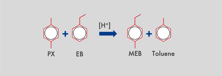
Much of the growth in this area is concentrated in xylene isomerisation ethylbenzene dealkylation (XI-EBD) type processes within an aromatics plant. In such a plant, C6-C10 aromatic molecules from a reformer or a steam cracker are processed further. Via distillation, benzene (C6); toluene (C7); PX, metaxylene (MX), OX and ethylbenzene (C8); and C9+ aromatic molecules are separated. Pure PX is the most valuable of the C8 molecules because it is a feedstock for the manufacture of PET plastics. The boiling points of the C8 molecules are too alike to allow separation by distillation. Instead, PX is removed from the stream via adsorption or crystallisation. The remaining C8 stream is then passed over a xylene isomerisation catalyst to form PX from MX and OX, after which the stream is recycled to extract further PX. To avoid the build-up of ethylbenzene in this cycle loop, ethylbenzene can be dealkylated to ethane and benzene (ethylbenzene dealkylation [EBD]) or reformed to xylenes (ethylbenzene reforming [EBR]). This is typically carried out in the same reactor as the xylene isomerisation.ZATARIS-21, Shell Catalysts & Technologies’ latest generation XI-EBD catalyst, has improved selectivity and is optimised to maximise PX or OX production yields, from a PX-lean and OX-lean xylene mixture.
September 2022 HYDROCARBON ENGINEERING 16
Figure
It is used in aromatic complexes, as shown in Figure 1. A typical aromatic complex takes a catalytically-reformed, heavy naphtha feed from refinery streams, or alternatively it takes pyrolysis gasoline (or pygas), which is a byproduct of making ethylene in a steam cracker. As PX is removed, using separation technology, the EBD and isomerisation unit restores an equilibrium mixture of para-, meta-, and ortho-xylenes. In this way, the other aromatic molecules are steadily converted to PX upon each pass through the EBD unit.As a drop-in upgrade, with no increase in plant footprint compared to industry standard catalysts, ZATARIS-21 provides exceptional preservation of the aromatic content of the feed, while offering high activity for reduced energy consumption. Requiring lower temperatures to keep the process running, the catalyst can also offer carbon dioxide (CO 2) emission reductions. Additionally, as aromatic hydrogenation is limited, less hydrogen is consumed.
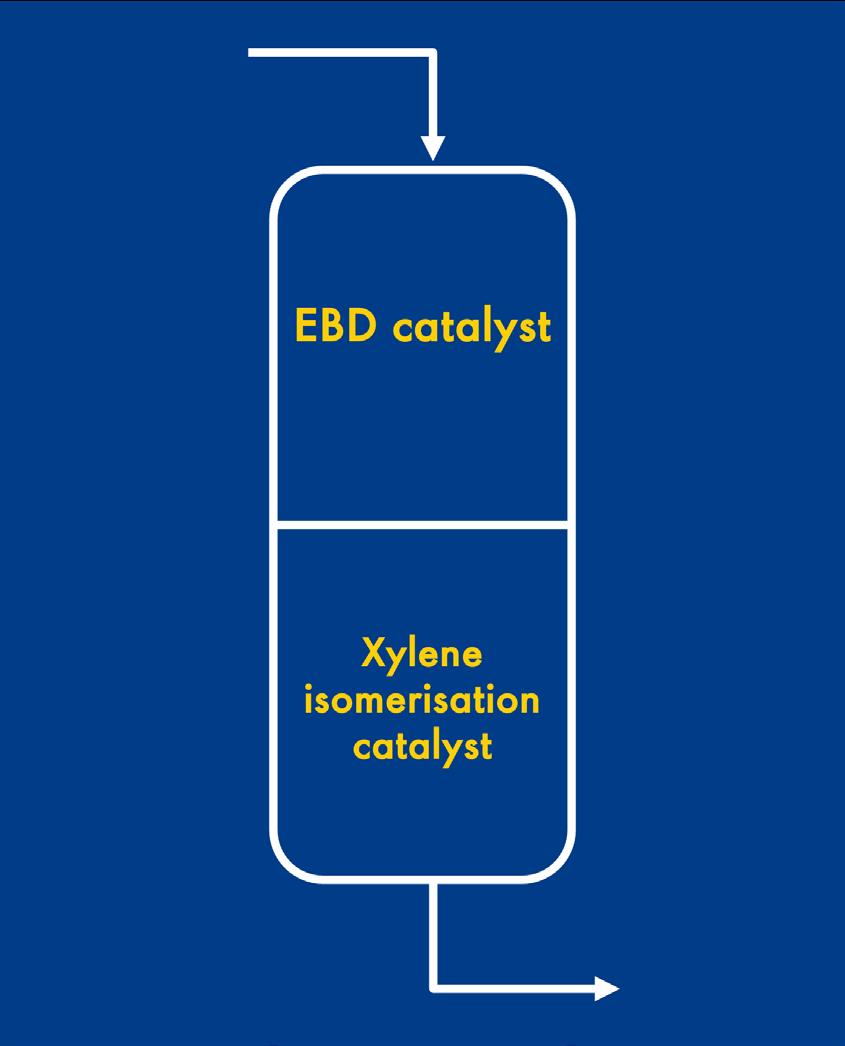
Historically, EBD catalysts, such as Z-8835 and its successor ZATARIS-20 (Figure 2), were single-bed that could be used for feeds with relatively high PX levels. Typically, these catalyst systems would last for a very long time –sometimes up to 20 years. As these legacy-generation catalysts offer robust performance, refiners are typically reluctant to try something new. Compared with the 1980s and 1990s, the mode of operation for these catalysts has changed substantially. Separation technology has improved in its efficiency to the extent that there are very low levels of PX in most feeds now. This requires the use of a redesigned catalyst that is fit for purpose, with very high selectivity.Tokeep in step with advances in separation technology, ZATARIS-21 operates within a dual-bed configuration. The first bed contains a zeolite-based catalyst where Figure 1. Typical aromatic complex.
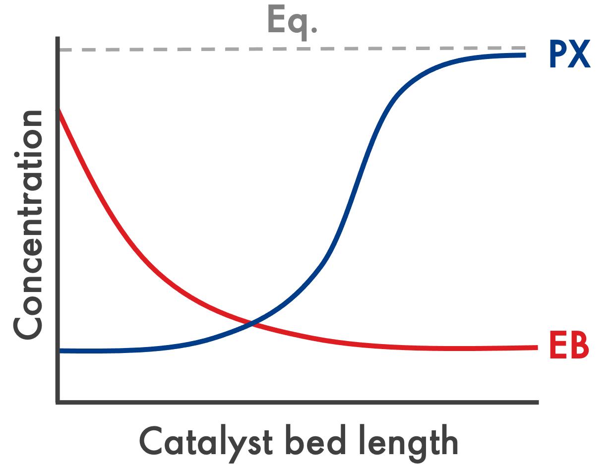

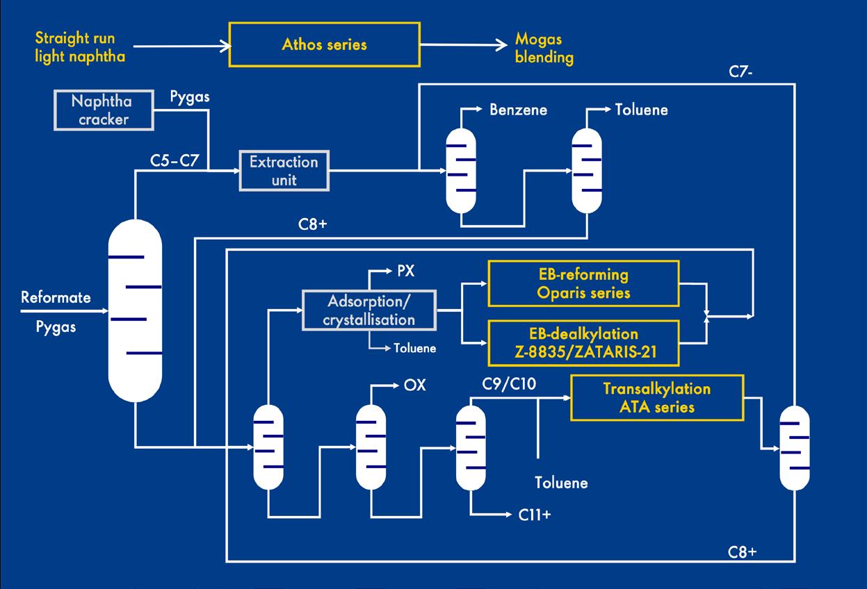

Figure 6. The molecular sizes of the aromatic molecules of interest.
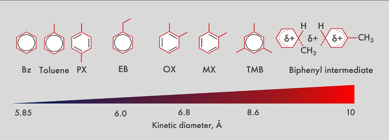
Figure 4. Typical EBD/xylene isomerisation catalyst configuration employed per reactor bed.
Passivated developmentzeolite
Figure 5. Density maps for aromatic molecules of different sizes, within (L-R) large, medium and small ZSM-5 crystals.

September 2022 HYDROCARBON ENGINEERING 18 EBD occurs. At this stage, the concentration of EB in the feed is rapidly depleted, indicated by the red curve on the graph in Figure 3. The second bed contains a catalyst that facilitates isomerisation reactions, converting xylenes to PX. As the isomerisation reactions take place in the second bed, the concentration of PX rises to an equilibrium concentration, as indicated by the blue curve on the graph in Figure 3. In contrast to a historic one-bed system, a stacked bed, as illustrated in Figure 4, contains independent catalysts and can be optimised. Depending on the feed, operating conditions, product requirements, and profit considerations, the ratio of each catalyst per bed can be tailored to provide greater feed flexibility. By decoupling the EBD and xylene isomerisation functions to a large degree, the overall performance of the catalyst system is significantly improved. Zeolite crystal size effect ZSM-5, a synthetic zeolite with a pore diameter range of five to six angstroms, was used as the basis of the ZATARIS-21 catalyst system. The crystal size of the EBD catalyst is highly important in determining which molecules diffuse all the way to the centre of the individual zeolite structures.1 Shell Catalysts & Technologies’ research revealed that large ZSM-5 crystals facilitate the diffusion of smaller molecules, such as EB, compared with larger molecules such as MX and OX. The large ZSM-5 crystals are therefore used in the ethylbenzene dealkylation catalyst, found in the first bed.Conversely, small ZSM-5 crystals are better for the conversion of larger molecules which diffuse slowly, such as MX and OX, so these crystals are used in the xylene isomerisation catalyst located in the second bed. The impact that crystal size has on the activity and selectivity of the catalyst is an important feature of the ZATARIS-21 system.Figure 5 shows cross-sections of ZSM-5 crystals with different sizes. Within the crystals, regions containing a high density of large aromatic molecules are represented by areas shaded in red. The blue areas indicate regions where a higher concentration of smaller aromatic molecules is found. For reference, the molecular sizes of the aromatic molecules of interest are indicated in Figure 6. Even though the catalyst in the first bed is highly size-selective, PX is small enough to fit into the zeolite and this will result in some unwanted side reactions (Figure 7). For this reason, a feed with low PX is both desirable and commonly encountered, given the modern separation technology used in most aromatic complexes today.
Researchers developed the catalyst in the first bed from a proprietary zeolite, ZSM-5, which was passivated to enhance selectivity.2 The passivation was achieved by depositing a thin layer of silica on the surface of the zeolite crystal, which further restricts molecular access to the pores. This means that the engineered zeolite system in the first bed selectively denies access to aromatic molecules that are larger than ethylbenzene, which has a kinetic diameter of about 6 angstroms. The size of the ethylbenzene molecule, relative to other aromatic molecules of interest, is shown in Figure 6.
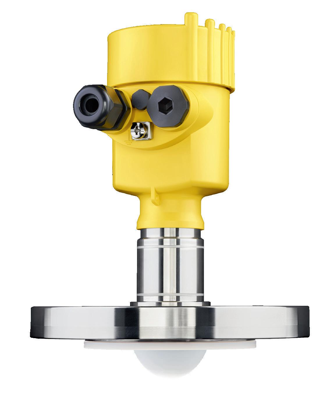
PRECISION,COMPATIBILITY.SIMPLICITY, THE 6X ®. OUT NOW! The new 6X radar level sensor is so easy to use, it’s simply a pleasure. Because we know customers value not just ‘perfect technology’, but also making everyday life better and less complicated. We wouldn’t be VEGA if measurement technology was our only value. VEGA. HOME OF VALUES. GET TO KNOW THE 6X® www.vega.com/radar

Metal function development: metal centre selectivity The selectivity of the metal function is critical to ensuring that the right molecules are hydrogenated. Ethylene must be quickly hydrogenated, whereas aromatics should not be hydrogenated because that would consume additional hydrogen and create naphthenes and gas with much lower value. By incorporating innovative design elements, the metal featured in ZATARIS-21 offers exceptional selectivity, with almost 100% aromatic ring retention. Researchers developed a metal catalyst based on a platinum surface alloy for the second bed, which is where the isomerisation takes place. In a conventional platinum catalyst, multiple metal atom centres are located close together, which facilitates the binding of aromatic rings across three or four platinum atoms (this is illustrated in Figure 9). As a result, unwanted hydrogenation of aromatics can take place.3 The technology developed in ZATARIS-21 places the active metal atoms in the matrix further apart by spacing inert atoms in between them. Olefins, requiring only one platinum atom centre, are selectively hydrogenated, thus preserving the valuable aromatic molecules.
Figure 9. Binding of aromatic rings to a conventional platinum metal catalyst, facilitating hydrogenation.

The silica layer is characterised in Figure 8, which shows a scanning transmission electron microscope (STEM-EDX) image of the passivated crystals. The silica layer is seen in yellow, whereas the light blue region is the ZSM-5 zeolite material.Owing to their smaller molecular size, benzene, toluene, PX, and EB can reside, and react, in the zeolite. The larger molecules (such as OX and MX) that cannot fit into the zeolite remain almost unreacted throughout the first catalyst bed. Consequently, the effective EB concentration in the zeolite, and hence the reaction rate, is increased by an order of magnitude, while at the same time xylene-loss side reactions are significantly reduced. When ethylbenzene reacts in the first catalyst bed, the ethyl group is removed from the benzene ring, producing benzene and ethylene. It is important that the reactive ethylene byproduct is hydrogenated to prevent re-alkylation and the formation of undesirable heavier molecules. This is where the metal function is highly important.
September 2022 HYDROCARBON ENGINEERING 20
Figure 10. Activity, selectivity, and ring retention data for ZATARIS-21, vs industry standard catalyst.
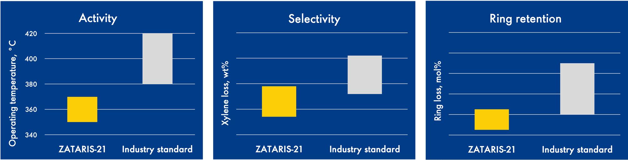
Figure 8. STEM-EDX image of the passivated zeolite crystals.
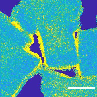
Without the silica layer passivation, larger aromatic molecules can enter the zeolite crystal.
Figure 7. The main side reactions that occur.
for a free trial SulphurPro® The ULTIMATE in Sulphur SimulationPlant Native Sulphur

Intensivepreservation.researchand development means that refiners can improve their feed efficiency, enabling more PX to be produced for a given amount of fresh feed. Fewer side products produced, along with lower gas and heavies, means that less hydrogen is consumed.Therobust catalyst system offers flexibility because the two-bed configuration facilitates tailoring of the two catalysts used. Owing to efficient dealkylation of EB and isomerisation of xylenes, minimal aromatic losses occur. The very limited xylene losses that do occur tend to result in the formation of toluene and C9+ aromatics, which can be recycled by routing to the transalkylation unit. The catalyst system therefore avoids the formation of significant amounts of low-value gases that cannot be recovered as an aromatic product. By using lower operating temperatures, refiners can realise improved process economics from a drop-in solution that requires no process modifications.
Performance benefits ZATARIS-21 offers impressive performance in terms of activity and selectivity. This results in lower operating temperatures, reduced CO2 emissions, and lower xylene losses (see Figure 10). To quantify the benefits of the new catalyst, compared to incumbent EBD catalyst systems, performance data can be compared using a modelling system. The refinery used for this comparison has a PX capacity of approximately 1 million tpy. The results reveal that PX production can be increased by approximately 67 tpd (from 3072 to 3139 tpd) by replacing the incumbent catalyst with ZATARIS-21. Economy of operation is improved by US$19 million/yr, due to the higher activity and selectivity of the new catalyst system. As a result of the lower operating temperature of the new catalyst, subject to catalyst load and EB conversion, energy savings of US$208 000/yr can be realised. This would correspond to a reduction in CO2 emissions of approximately 4900 tpy.
Conclusion The ZATARIS-21 catalyst system achieves significant activity and selectivity gains by deploying a dual-bed catalyst configuration. Novel design features include engineered ZSM-5 crystals containing groundbreaking passivation technology and a platinum metal function where the metal centres are optimally separated for aromatics
References 1. DEMIKHOVA, N. R., RUBTSOVA, M. I., VINOKUROV, V. A., and GLOTOV, A.P., ‘Isomerisation of xylenes (a review)’, Petroleum Chemistry , (November 2021). 2. ZHENG, S., JENTYS, A., and LERCHER, J., ‘Xylene isomerisation with surface-modified HZSM-5 zeolite catalysts: An in situ IR study’, Journal of Catalysis , (2006), 241, pp. 304 – 311. 3. DENG, Y., GUO, Y., and JIA, Z., et al., ‘Few-atom Pt ensembles enable efficient catalytic cyclohexane dehydrogenation for hydrogen production’, Journal of the American Chemical Society , (2022), 144, pp. 3535 − 3542.
September 2022HYDROCARBON ENGINEERING 21
Contact us
Optimized Gas Treating, Inc 212 Cimarron Park Loop, Buda, TX 78610 www.ogtrt.com +1 512 312 9424
22September 2022 HYDROCARBON ENGINEERING

Reaction pathways in lipids conversion
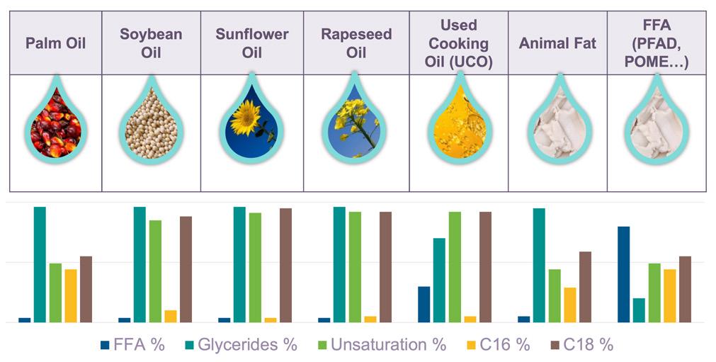
Despite the availability of many different types of oils and fats on the market today, they are all essentially chemically-analogous, as they are mostly composed of free fatty acids (FFA) and glycerides, with different degrees of unsaturation and chain lengths, as shown in Figure 1.
Although the refining industry has extensive experience in producing fossil fuels, the simultaneous processing of renewable material along with fossil-based blendstock presents new technical challenges related to catalyst and process design which require new competences, and need to be addressed with a robust approach.

September 202223HYDROCARBON ENGINEERING
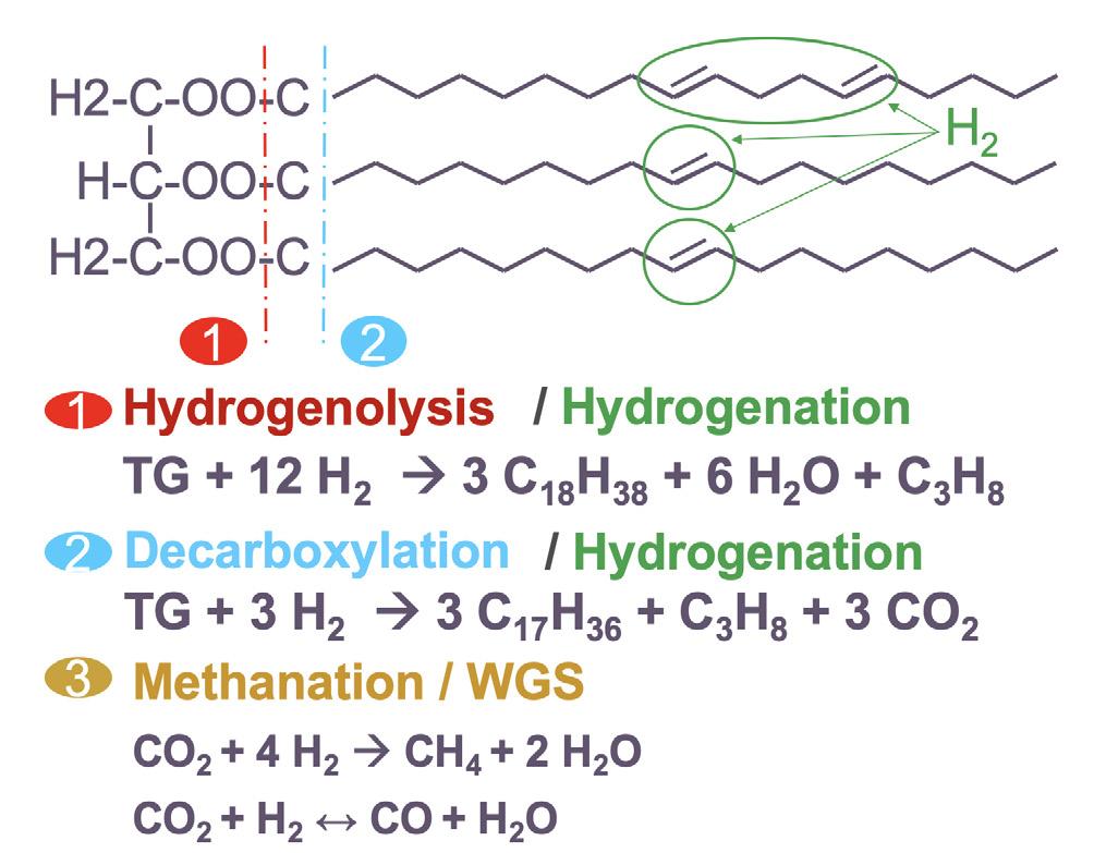
Since the sulfur and nitrogen content of these feeds is naturally low compared to fossil feedstocks, the fundamental challenge when hydroprocessing them is to produce the deoxygenated bio-sourced hydrocarbon products that not only fall in the same boiling range, but are also fully compatible with the existing fuel platform. Under typical hydroprocessing operating conditions, the rapid saturation of double bonds will be followed by the disconnection of the paraffinic chain from the glyceride backbone. This last step can take two different dominant reaction pathways (see Figure 2): n The hydrodeoxygenation (HDO) pathway consists of hydrogenation to produce water, propane, and a normal paraffin that has the same length as the corresponding fatty acid chain. n The decarboxylation (DCO) pathway, in turn, involves a C-C bond break to produce carbon dioxide (CO2), propane, and a normal paraffin that is one carbon atom shorter than the corresponding fatty acid chain. These simultaneous deoxygenation routes produce CO2 and water (H2O), which undergo further methanation and water gas shift reactions that define the final balance between the carbon monoxide (CO)/CO2/H2O/methane (CH4) species in the reactor effluent. Selectivity towards HDO is normally desired, as it maximises paraffin mass yield, while simultaneously minimising CO/CO2 production. Mastering these Lucas Vergara, Axens, France, presents catalytic solutions to help tackle the challenges associated with co-processing sustainable feeds.
R ecent changes in legislation and mandates have propelled a sharp rise in global demand for sustainable fuels, challenging refiners to rapidly integrate hydroprocessing renewable feedstock solutions into their existing infrastructure. While large investments in dedicated oils and fats processing facilities are still years away from coming onstream, a drop-in co-processing solution presents an immediately-available, low-CAPEX stepping stone on the path towards decarbonisation.Moreover,driven by RFS/LCFS and RED II policies, the significant expansions recently announced in the US and Europe will soon place a massive constraint on the global bio-based feedstock market. Not only is it crucial for refineries to be an early adopter, but it is also paramount that the best strategic approach is taken to widen feed options and consider other unconventional advanced alternatives that are not in direct competition with food, such as bio-oils and pyrolysis oils.
Renewable lipid feeds co-processing challenges
n Localised high consumption of hydrogen, in rapid exothermic double bounds saturation and deoxygenation reactions, may lead to accelerated pressure drop build-up and premature catalyst ageing.
September 2022 HYDROCARBON ENGINEERING 24 mechanisms at play requires the best catalytic design and process configuration solutions.
n At the same time, deoxygenation results in significant amounts of propane, water, CO, CO 2 and methane byproducts which need to be removed from the recycle loop to avoid having a negative impact on hydrogen partial pressure and recycle gas compressor performance.
n Additionally, in the reactor effluent train, some of these reaction byproducts may accelerate piping and equipment corrosion rates, and increase the formation of ammonium salts.
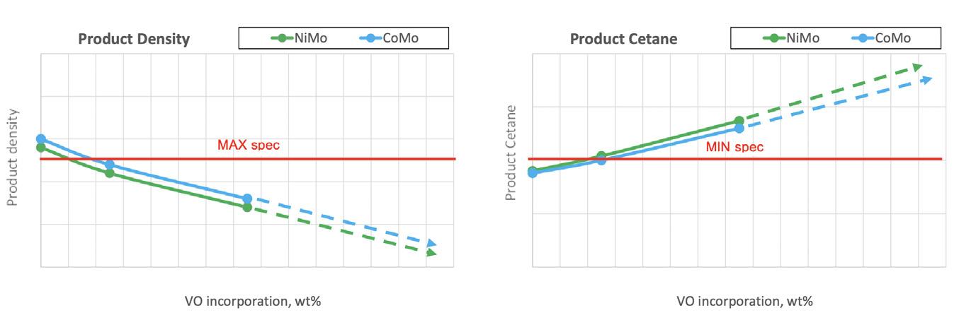
Figureshownnumber,cetanedensitysuchproperties,dieselofimprovementsignificantinproductendresultthesomekeyasandasin3,but
n Phospholipids, which are naturally present in lipid biogenic material, tend to precipitate at high temperatures, leading to fouling concerns at the level of feed and reaction section.
n CO in particular, which is not effectively removed by amine gas treating systems, is known to also selectively inhibit CoMo hydrotreating catalyst promoters’ activity by blocking access of sulfur and nitrogen-containing species to the catalytic sites.
When considering repurposing an existing hydroprocessing unit to perform co-processing, it is critical to first evaluate the potential risk factors and consequences (see Table 1), in order to mitigate them with the best process design practices and catalytic solutions. Due to its nature, renewable lipid material has new and different quantities of contaminants, such as FFAs, phospholipids, chloride and metals, as well as a larger amount of highly-reactive species. Even though the content of impurities can be, to some extent, controlled by feed selection and level of pre-treatment, some remaining quantity is always present. Consequently, processing this type of material results in additional difficulties that are mainly related to the control of the reactor pressure drop and the very exothermic reactions, as well as increased corrosion in the feed and effluent sections:
n FFAs are the carboxylic acid product of the chains that have broken off from the glycerol backbone of the triglycerides, by degradation of the feed. Even though their corrosive effect is reduced by dilution with mineral oil feed, rich FFA feeds can still cause damage to pipes and equipment in the feed system.
Figure
Finally, the linear paraffins in the
1. The wide spectrum of lipid feeds. Figure 2. An example of C18 triglyceride conversion pathways. Table 1. The challenges presented by renewable lipid feeds Renewable feed challenges Impacts oilVegetable Waste oil (UCO) Animal fats POME/FFAD Tall oil FFA Corrosion on reactorsection/preheatfeedtrain/ + + +++ +++ Phospholipids Pressure drop build-up and catalyst poisoning ++ ++ +++ + + Metals Pressure drop build-up and catalyst poisoning ++ ++ +++ + + Chloride Corrosion on effluent side +++ + + Poly-unsaturates exotherm,consumption,Hydrogenrisk of fouling +++ ++ + ++ +++
Reserved.RightsAllHalliburton.2022© Water and Process Treatment SUPERIOR SERVICE AND CHEMICAL APPLICATION EXPERTISE TO MAXIMIZE ASSET VALUE Our experienced team provides customized water and process treatments, dedicated engineering, and expert technical support to refineries worldwide. We can help you improve reliability, increase throughput, and enhance the efficiency and flexibility of your operating units. We have a proven history of working with refineries to identify, deliver, and document process improvements and cost avoidance. halliburton.com

Depending on the original plant configuration, the combination of all of these factors imposes diverse constraints with regards to the amount of renewable feed that can be successfully co-processed in a given unit. In this context, refiners have followed a progressive approach to this problem, by incrementally investing in catalyst and hardware upgrades to provide access to better economics through improved co-processing rates.
Catalyst technology as a keystone to tackling the challenges of co-processing
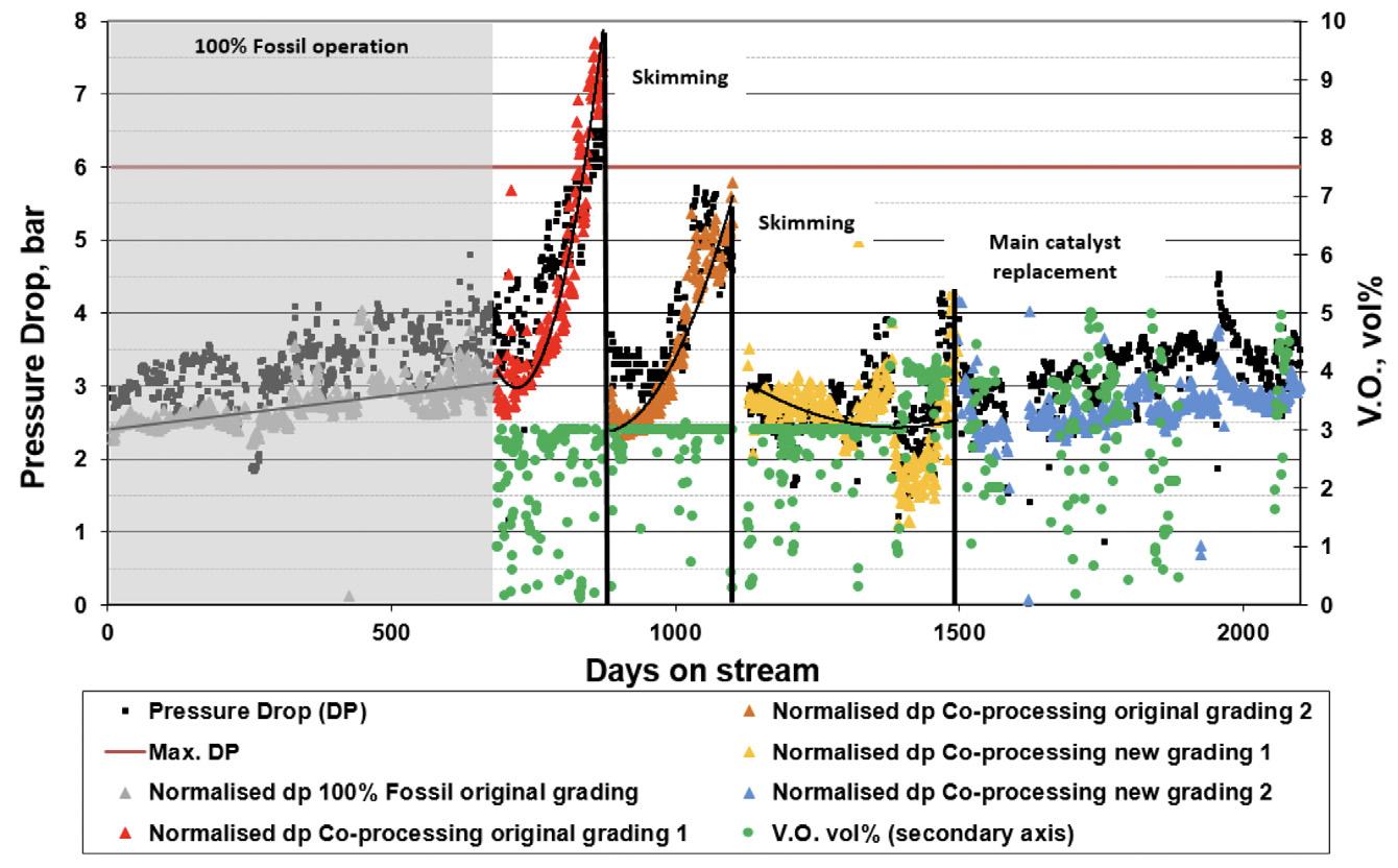
To illustrate the relevance of having a proper grading system in place, even at low levels of co-processing, Figure 4 presents the industrial feedback of a diesel hydrotreater unit in a European refinery, and shows the evolution of the normalised pressure drop across the reactor beds. Motivated by the changes in legislation, and after two years of stable operation processing mineral feed, this refinery decided to start co-processing a maximum of 3 vol% of vegetable oil along with the existing fossil diesel, using its original grading system. After introducing the bio-feed, the reactor pressure drop quickly began to increase, reaching – within a few months’ time – the point where the unit had to be briefly shut down for two consecutive skimming operations to replace the top layers of the grading arrangement. A comprehensive analysis of the recovered material allowed Axens to design the optimum reactor loading configuration, which was later installed, and remains to this day in stable condition, after 18 months in continuous co-processing service.
September 2022 HYDROCARBON ENGINEERING 26 they may also end up detrimentally affecting cold flow properties.Giventhat, in this service, the use of improvers and modification of product cut points have a limited effect on end product cold flow properties, operators ultimately consider implementing dedicated catalytic dewaxing solutions to produce different commercial diesel grades.
Both the HDO and DCO reaction mechanisms for renewable feed conversion described in the previous section are catalysed by the same types of metal sulfide catalysts used for conventional hydrotreating. At the same time, the high sulfur content of the fossil feed ensures that the active phase remains in the sulfide form.
Grading technology to maximise run length Proper management of all previously-mentioned factors requires the use of top performance catalyst systems and a careful selection of the reaction conditions. After extensive pilot testing and industrial experience, Axens developed a robust, comprehensive solution that can cope with these extreme challenges and help producers to achieve a stable operation during long runs, while meeting all product specifications.Tobeginwith, feed pollutants and hydrogen depletion, due to double-bond saturation at the top part of the catalyst bed, can pose the associated risks of fouling, pressure drop build-up, and premature loss of activity.
Hydrotreating catalyst technology: a matter of balance
Tackling these challenges requires the installation of a dedicated grading design that provides not only a mild hydrogenation activity but also includes a demetallisation catalyst, to guarantee that the impurities will not break through and reach the active catalyst. When aiming to process lightly pre-treated renewable material with conventional fossil feeds, this grading solution can also be complemented with a Hy-Clean® bypassable smart filtering distributor tray system, allowing for optimal control of the pressure drop build-up.
Figure 4. The impact of the co-processing of lipid feeds on reactor pressure drop.
Figure 3. The impact of the co-processing of lipid feeds on final diesel density and cetane.
Case study
© 2022 Koch Engineered Solutions. All rights reserved.
Sustainability is your goal. Stewardship is our North Star. We’re going the same way — toward a cleaner, more prosperous world. Our connected companies create environmental solutions that can help get you there faster and thrive. Carbon capture and reduction. Reliability and energy efficiency. Emissions reduction. Renewable energy. Managing water and waste. It’s a journey. We partner with you to create superior value for long-term results.
A SUSTAINABLE PARTNERSHIP
VISIT OUR LOUNGE at the AFPM Summit, October 18-20, 2022. Discover more at koch.link/StewardshipKES or scan the QR code.

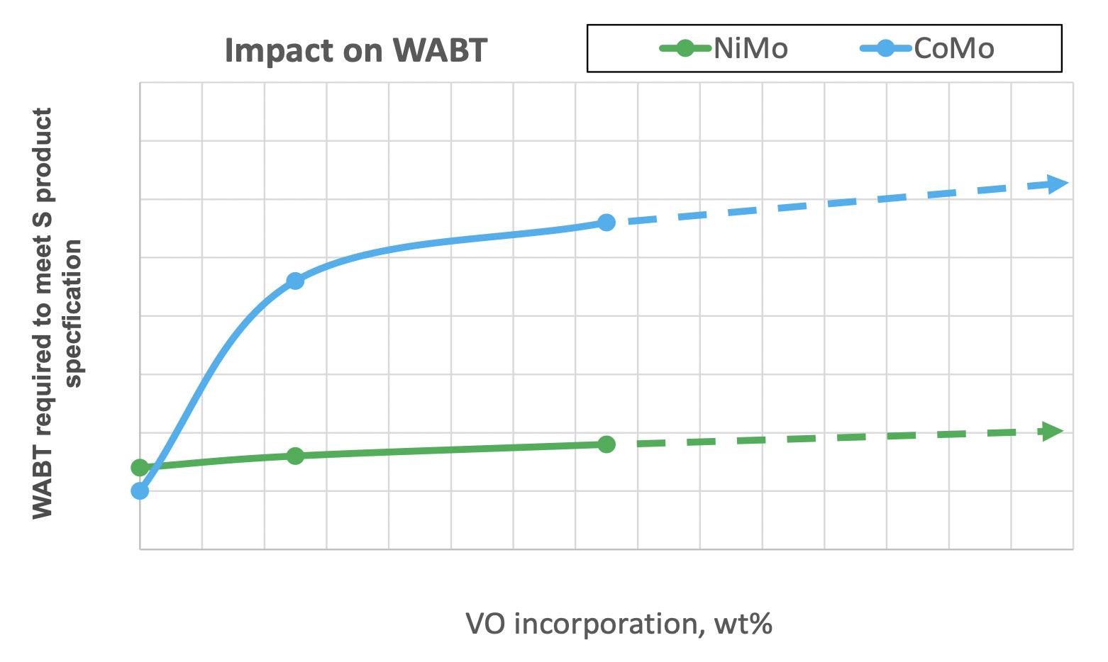
Figure 5. The impact of the co-processing of lipid feeds on reactor WABT.
While the first type can show better yields by retaining product molecules in the diesel boiling range, their catalytic activity is highly sensitive to inhibitors, thus requiring a separate reaction stage. In turn, the second family of catalyst can be placed at the bottom of an existing reactor, providing a low-cost solution with the flexibility to produce different grades of refined products (e.g. winter and summer diesel) by adjusting its operating temperature with the use of quench gas. Although slightly lower diesel yields are obtainable, there is an increasing market interest in bio-LPG and bio-naphtha products.
Therefore, main hydrotreating catalyst selection for co-processing operation presents a unique challenge as it is required to find the right balance between high desulfurisation/denitrogenation activity, and a gradual conversion of the highly-reactive renewable feed components that otherwise would provoke hydrogen starvation, leading to coke formation and pore-mouth plugging.Considering all of these factors, Axens developed HDO-selective NiMo catalyst formulations that are highly tolerant to CO inhibition (Axens’ 700-series catalyst) and that, in a synergetic arrangement with the tailor-made grading solution, maximise run time. Figure 5 reveals the different expected effects of CO in standard hydroprocessing NiMo and CoMo catalyst activity. Furthermore, by performing a controlled conversion of the renewable feed with a highly active HDS catalyst, not only are the cycle lengths extended, but the lower operating temperature required to meet the sulfur product specification also favours the catalyst selectivity towards the hydrogenolysis pathway, providing better overall product yields.
As previously discussed, a high linear paraffins content in the final product will result in cold flow property degradation and may dictate the need for a dedicated catalytic dewaxing solution to comply with the most severe market requirements. Currently-available catalytic dewaxing solutions on the market can be generally categorised into two different types of bi-functional catalysts: n Catalysts based on noble metals, which selectively isomerise the linear paraffins to produce multi-branched iso-paraffin molecules. n Catalysts based on base metals, which improve the cold flow properties by a combination of isomerisation and hydrocracking of the normal paraffins.
Conclusion A combination of a rapidly rising demand for sustainable fuels with the significant lead time and investment associated with dedicated production units makes co-processing the perfect fast-to-market leap, providing refiners access to an ever-growing market with maximum use of existing assets. In addition to this, with great versatility to process feeds of a diverse and complex nature, co-processing technology may well co-exist to complement and expand refineries’ future operation on alternative circular economy feeds. Axens, with extensive knowledge of process design and corrosion engineering, reaction chemistry and catalyst technology, paves the way with innovative pragmatic drop-in solutions that provide producers with customised and cost-effective options to co-process a wide range of sustainable feedstocks with minimum investment and quick returns, while maintaining excellent operating performance throughout the cycle.
Hydrocracking catalyst technology for optimum product slate In the hydrotreating process, the renewable material deoxygenation reactions take place on active metal sites, whereas in the hydrocracking catalyst the acid sites of the zeolite carrier promote cracking and isomerisation of the normal paraffins. Lately, this particular feature has brought focus to the hydrocracking technology, as it provides an economical pathway to produce sustainable aviation fuel (SAF).Axens’ zeolite-based hydrocracking catalyst can be grouped into two distinct families: one that provides maximum viscosity index improvement for the unconverted oil (Cracken Flex® product line), and one that guarantees maximum middle distillate yields with improved product cold flow properties (Cracken D® product line).
September 2022 HYDROCARBON ENGINEERING 28
By selecting the appropriate hydrocracking catalyst formulation, it is possible to preserve similar unit performance while achieving an attractive yield of isomerised bio-paraffins that not only fall in the jet fuel boiling range, but also contribute to meet most stringent commercial product cold flow specifications.
Dewaxing catalyst technology to meet the most stringent cold flow specifications
September 202229HYDROCARBON ENGINEERING
T he negative impacts of greenhouse gases such as carbon dioxide (CO 2 ) are widely recognised as complex challenges. It is essential to move away from our dependence on petroleum-based products, from both an environmental and economic perspective. Although petrochemicals are the predominant feedstock in the chemical industry, the utilisation of renewable feedstocks to produce chemicals is taking off, with the aim of reducing carbon footprint in order for various base chemicals to have a positive environmental impact. 1 As such, it is important to seek alternative platform base chemicals that are based on sustainable green chemistry in order to support the manufacture of the important products used in our daily lives. Aside from the option of finding drop-in solutions to existing fossil-based platform chemicals, the switch towards renewable feedstocks allows for – and Gisa Meissner and Konrad Krois, Heraeus Deutschland GmbH & Co. KG, Germany, discuss the use of precious metal-based catalysts for the efficient conversion of 5-hydroxymethyl furfural (5-HMF) into 2,5-diformylfuran (DFF) to produce phenolic resins.

The paradigm shift towards, and market demand for, renewable feedstocks in the chemical industry was recognised by Heraeus several years ago, initiating a development programme for precious metal-based catalysts targeting the conversion of various renewable feedstocks such as biomass, CO 2 or waste plastics into value-added, sustainable chemicals (Figure 1). Generally, these chemicals, derived from renewable feedstocks such as biomass i.e. sugarcane, harvest or wood residues, have a significantly smaller carbon footprint and have a better life cycle assessment compared to their fossil-based counterparts. Forestry residues, such as lignin or 5-hydroxymethyl furfural (HMF) from cellulose, can serve as a renewable source for value-added chemicals. 6, 7
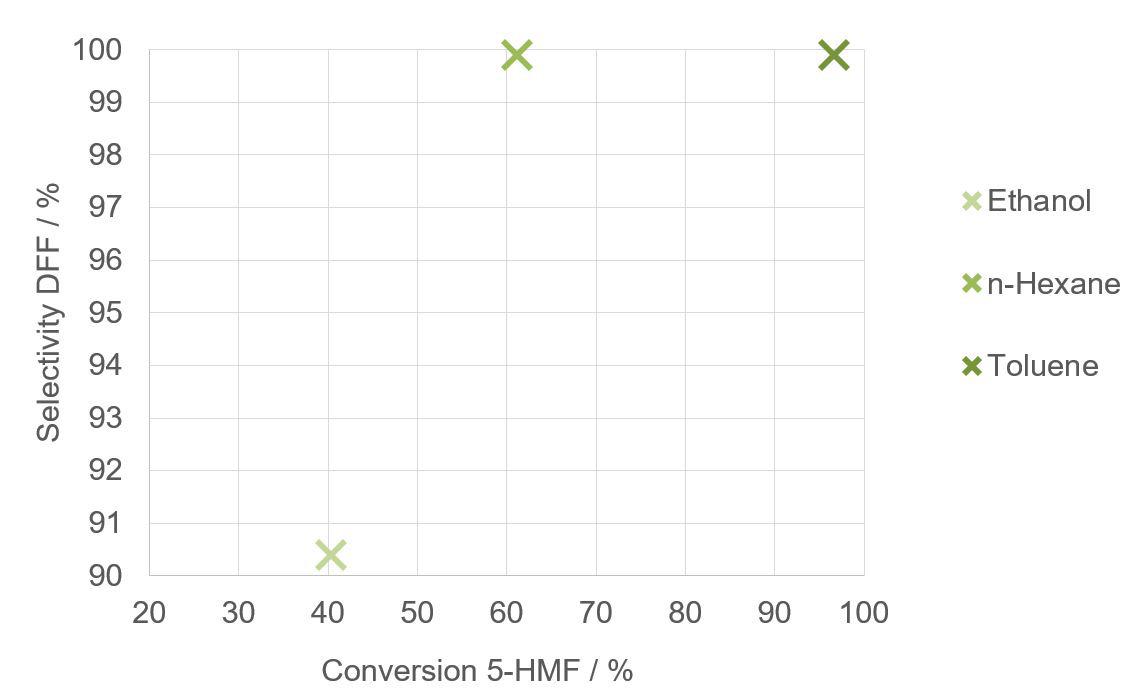
Figure 2. Solvent-screening results for the oxidation of 5-HMF into DFF using a 3%Ru/Al2O3 catalyst with molecular oxygen, after 3 hr reaction time.
One such platform can be 2,5-diformylfuran (DFF), which is a highly-flexible chemical that can be used for a variety of bio-based products, such as plastic bottles, where it replaces terephthalic acid after a catalytic oxidation step. Additionally, polyamides, polyurethanes and many other products can be derived from this platform chemical. In particular, DFF facilitates the production of formaldehyde-free phenolic resins as glue for chipboards in the furniture industry, for example.Thisarticle focuses on the development of efficient oxidation of 5-HMF into DFF. The use of heterogeneous Ru/Al 2 O 3 catalysts leads to the complete conversion of 5-HMF, as well as the selective formation of DFF with molecular oxygen. Both ruthenium loading and the selected support material influence the catalyst performance. Furthermore, the recovery and recycling of ruthenium as precious metal is of great importance from an ecological and economical point of view. The next section will highlight strategies to obtain organic building blocks and platform chemicals from renewable feedstocks by the effective deployment of precious metal-based catalysts. It will also discuss the cost attractiveness of precious metal-based catalysts, when applying recycling loop strategies, which allow for the efficient use of the scarce precious metals.

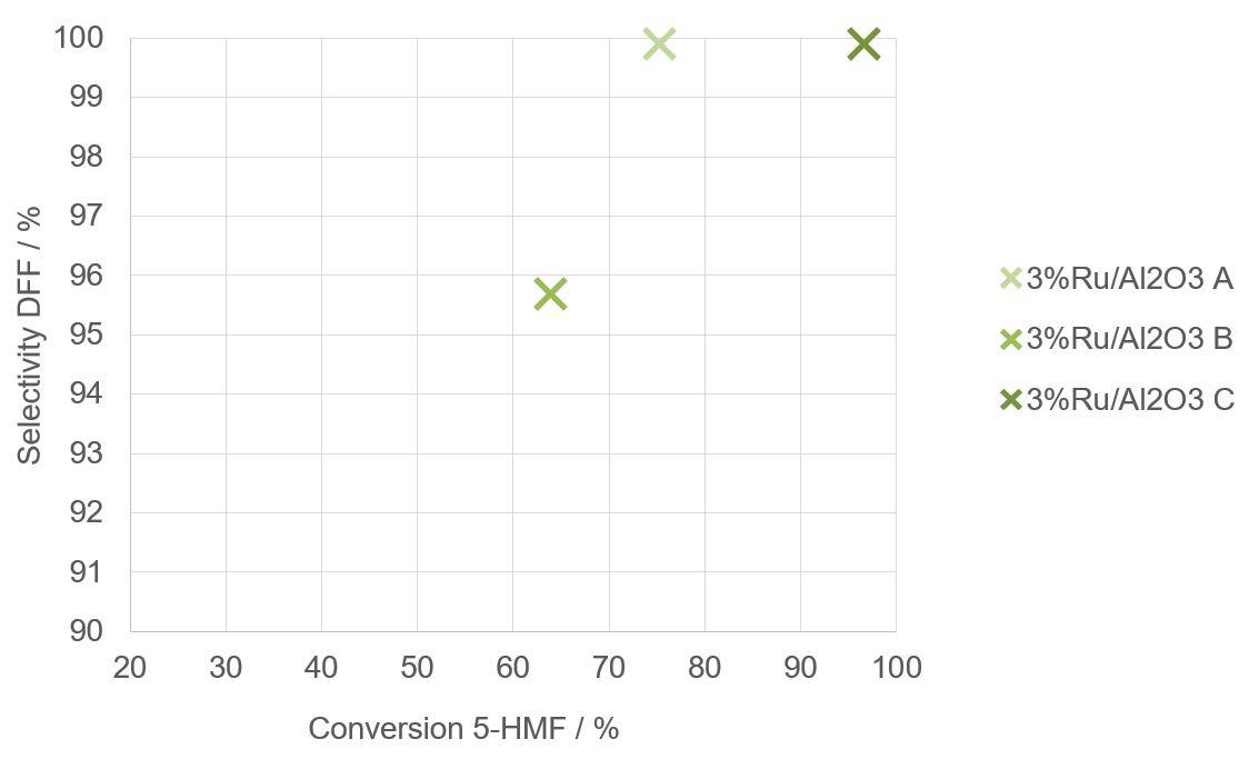
Figure 3. Results of the support influence for the oxidation of 5-HMF into DFF using different 3%Ru/Al2O3 catalysts with molecular oxygen in toluene, after 3 hr reaction time.
September 2022 HYDROCARBON ENGINEERING 30 sometimes even mandates – entirely new and different process routes. Consequently, this leads to chemicals with new functionalities and properties that previously had no economic pathway, allowing for further value creation. Whereas many renewable feedstock-based chemicals are derived from the use of biochemical routes, traditional chemical catalysis and processes remain a cornerstone for the conversion of renewable feedstocks. At present, more than 80% of processes deployed on an industrial scale use different catalysts for the synthesis of a variety of chemical, petrochemical and biochemical products, as well as polymers. 2 According to the 12 principles of green chemistry, selectivity, efficiency and sustainability play a pivotal role in chemical processes as a whole. 3
Figure 1. 5%Ru/Al2O3 catalyst for the effective conversion of 5-HMF in DFF.
Chemical intermediates based on renewable feedstocks can be properly integrated into the traditional chemical industry by using heterogeneous precious metal-based catalysts, and these also align with the principles of green chemistry. 4, 5
Precious-metal catalysts for the efficient conversion of 5-HMF Heraeus is actively developing and optimising catalysts for conversion processes of renewable feedstocks, together with partners from industry and academia. The Competence Centers for Excellent Technologies (Comet),
The 2022 API Storage Tank Conference will give attendees an opportunity to learn about new and existing industry codes and standards, and to hear about emerging trends from industry experts. This conference offers over 25 sessions addressing the needs of individuals involved in production systems, pipelines, terminals, refining, and storage facilities. Each day focuses on presentations relevant to upstream, midstream and downstream. Copyright 2022– American Petroleum Institute, all rights reserved. API, and the API logo are trademarks or registered trademarks of API in the United States and/or other countries. API Globa Marketing & Creative: 2022-084 | 05.26 Register at www.API.org/storagetank CONFERENCE & EXPO 2022 API STORAGE TANK OCTOBER 10-13, 2022 | MARRIOTT MARQUIS SAN DIEGO MARINA, SAN DIEGO, CALIFORNIA

7. DERFLINGER, C., KAMM, B., and PAULIK, C., International Journal of biobased plastics , (2021), https://doi.org/10.1080/2475965 1.2021.1877025
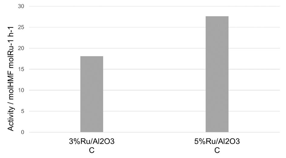
It is noteworthy that no 5-formyl-2-furancarboxylic acid (FFCA), 5-hydroxymethyl-2 furancarboxylic acid (HMFCA) or 2,5-furandicarboxylic acid (FDCA) were detected as over-oxidation products with these Ru/Al 2 O 3 Followingcatalysts.this, Heraeus investigated the influence of the ruthenium loading of catalyst C. Interestingly, the higher the ruthenium loading of the catalyst, the higher
4. PINEDA, A., and LEE, A. F., Applied Petrochemical Research , (2016), https://doi.org/10.1007/s13203-016-0157-y
The catalyst performance not only depends on the solvent chosen, but also on the precious metal precursor solutions that are used, e.g. ruthenium chloride or ruthenium nitrosyl nitrate, as well as on the intrinsic characteristics of the support. To investigate the influence of the support, three 3%Ru/Al 2 O 3 catalysts (A, B and C) were tested on different alumina supports (see Figure 3). The highest HMF conversion of 97% with a DFF selectivity of 99.9% was obtained using an alumina support with a BET area of 155 m 2 /g (ruthenium catalyst C). This support lead to a reaction rate that was almost twice in comparison to the other catalysts.
5. KOHLI, K., PRAJAPATI, R., and SHARMA, B.K., Energies , (2019), https://doi.org/10.3390/en12020233
Figure 4. Results of the ruthenium loading influence for the oxidation of 5-HMF into DFF, using a 3%Ru/Al2O3 and 5%Ru/Al2O3 catalysts with molecular oxygen in toluene, after 3 hr reaction time.
6. SUESS, R., KAMM, B., ARNEZEDER, D., et al., The Canadian Journal of Chemical Engineering , (2021), https://doi.org/10.1002/cjce.24055
3. POLIAKOFF, M., and LICENCE, P., Nature, (2007), https://doi.org/10.1038/450810a
2. DEUTSCHMANN, O., KNÖZINGER, H., et al., Ullmann’s Encyclopedia of Industrial Chemistry, Wiley-VCH, (2000), https://doi.org/10.1002/14356007.a05_313.pub2
Note The authors would like to thank Birgit Kamm and Christoph Derflinger for their work on the project ‘Wood K plus Comet Funding Period 2019 – 2022’, funded by the Austrian Research Funding Association (FFG).
September 2022 HYDROCARBON ENGINEERING 32 a technology cooperation programme founded by the Austrian government, focuses on the valorisation of organic materials and total biomass utilisation into sustainable products and energy. Native biopolymers from woody biomass are separated to obtain 5-HMF from cellulose as a starting material for DFF for bio-based products, such as phenolic resins with a substitution of formaldehyde. Heraeus developed a new ruthenium-based catalyst for the efficient formation of DFF from 5-HMF as an important bio-based platform chemical. The heterogeneous catalytic oxidation of 5-HMF with molecular oxygen leads to the selective formation of DFF.Different solvents were tested using a 3%Ru/Al 2 O 3 catalyst prior to the catalyst screening (see Figure 2). In comparison to polar protic solvents, such as water or ethanol, a total selectivity towards DFF was found for non-polar solvents, such as hexane and toluene. Since toluene not only produced the highest DFF selectivity, but also a full HMF conversion, it was chosen as the most suitable solvent for further investigations.
the catalyst activity towards the formation of DFF (see Figure 4). Without ruthenium, the activity is very low, with only 0.1 mol (HMF) mol (Ru) -1 h -1 . In contrast, activity of 18 mol (HMF) mol (Ru) -1 h -1 is observed, with a loading of 3% ruthenium. This was improved, and a 5% ruthenium loading lead to an activity of 28 mol (HMF) mol (Ru) -1 h -1 After washing, this 5%Ru/Al 2 O 3 catalyst can be reused several times. Nevertheless, after the catalyst is deactivated, the precious metals recovery plays a key role from both an ecological and economical point of view. The full ‘precious metal loop’ offered by Heraeus consists of the precious metal winning, the production of precious metal solutions, as well as the catalyst synthesis, followed by its performance as an active catalyst. Finally, the deactivated catalyst is separated from the reaction mixture to close the loop with the precious metal recycling, which again serves as a precious metal source. This catalyst recycling is not only cost competitive, but also ecological. The recycled secondary precious metal can reduce the carbon footprint by up to 98% in comparison to primary precious metal from mining.
References 1. LI, C., ZHAO, X., and WANG, A., et al., Chemical Reviews , (2015), https://doi.org/10.1021/acs.chemrev.5b00155
Conclusion DFF is a promising platform chemical derived from renewable feedstocks from which a variety of bio-based products can be manufactured. Heraeus has therefore developed an efficient catalyst for the oxidation of 5-HMF to DFF. The use of a heterogeneous Ru/Al 2 O 3 catalyst with an optimised choice of precious metal precursor and support material leads to a large increase in activity relative to a non-optimised catalyst. A complete conversion of 5-HMF and the selective formation of DFF without the formation of the over-oxidation products, HMFCA or FDCA, is possible. Furthermore, the activity could be further optimised by increasing the ruthenium loading of the catalyst by up to 5%. Heraeus offers a comprehensive product and service portfolio along the precious metals value chain – from catalysts to recycling.
An MOF is a compound of metal ions and organic linkers that form structures with extremely high porosities and large specific surface areas – up to almost 9000 m 2 /g. These compounds were discovered at the end of the 1990s, and more than 90 000 MOFs have been synthesised since then. Thanks to their versatility, more than 500 000 possible MOFs have been predicted, with many structures and accessible metal centres of any nature, in any coordination and organic functionality. 1
Applications of MOFs MOFs have a very relevant role to play in the energy transition, proof of which is the recent growth in interest in the applications of these materials in the field of energy. This section will review some of these.

T
Dr. M. Asunción Molina Esquinas, Instituto de Catálisis y Petroleoquímica, and Dr. Meritxell Vila, MERYT Catalysts & Innovation, explain why metal-organic frameworks (MOFs) have an essential role to play in helping the energy sector to achieve its energy transition and independence goals.
September 202233HYDROCARBON ENGINEERING
he need to develop new catalysts as a result of the energy transition has been further increased with the realisation, as a result of the war in Ukraine, that energy independence is important. This article will focus on metal-organic frameworks (MOFs), and what role they can play in achieving this. What is an MOF?
In order to improve the low temperatures and high pressures required to achieve sufficient energy density, the pore size of the MOFs dedicated to storage must be very similar to the dimensions of the molecule, due to the low interaction between hydrogen and the adsorbent surfaces under normal conditions. Additionally, the presence of unsaturated metal sites with a low coordination number plays a crucial role in this process. Kapelewski et al published an important paper on the hydrogen storage capacity of M-MOF-74 (M = Co, Ni) at near-ambient temperatures. 8 Ni-MOF-74 was the MOF with the highest volumetric capacity (11.0 g/l) at pressures between 5 – 100 bar, making it the adsorbent known to have the highest hydrogen storage capacity under these conditions. The authors attributed its high storage capacity to the presence of highly-polarising Ni 2+ adsorption sites. Conventional methane storage methods are expensive and have some major safety issues. To extend the use of this fuel to other applications, improved storage systems are needed. Again, MOFs present themselves as a solution. Both the presence of open Figure 1. Crystal structure of some MOFs and their Brunauer-Emmett-Teller (BET) surface area.
Hydrogen and methane storage Replacing traditional fossil fuels with more environmentally-friendly gaseous fuels such as hydrogen and methane is a challenge in terms of transport and storage. The use of gaseous fuels demands operating conditions that are challenging, as well as high energy costs. The large surface area of MOFs allows them to adsorb hydrogen and methane by reducing the pressure needed to densify them. Gas storage is another major application for these materials, and the following section will introduce a few examples.
CO 2 conversion Due to their high porosity and large surface area, the high affinity between MOFs and CO 2 , and because they can provide a platform that combines all of the necessary elements into a single material, MOFs have emerged as strong materials for CO 2 conversion into usable chemical energy or fuels to achieve a carbon-neutral cycle, such as methane (CH 4 ), carbon monoxide (CO), formic acid (HCOOH), formaldehyde (HCHO), methanol (CH 3 OH) or ethanol (C 2 H 5 OH). Chen et al added Ni 2+ into the NH 2 -MIL-125-Ti structure to modulate the electronic structure of the metal clusters and control the charge transfer efficiency and photocatalytic performance. 6 Doping with 1% Ni 2+ increased the CO conversion rate and photocatalytic efficiency by more than five times, reaching a selectivity of more than 98%. By increasing the doping to 1.5% Ni 2+ , the photocatalyst showed selectivity towards CH 4 Zhen et al reported a multiple impregnation strategy to encapsulate Ni nanoparticles in a highly-ordered MIL-101. 7 The catalyst displayed positive characteristics to be employed in the hydrogenation of CO 2 to CH 4 at low temperatures. It was found that the high dispersion, morphology and size of the Ni nanoparticles that was stabilised in the MOF structure played a key role in the high activity of the catalyst in the reaction.
The production of fuels such as hydrogen, from clean energy sources such as solar energy and green raw materials, such as water, is key to the energy transition. There are some features that mean that these materials are major players in the field of photocatalysis. For example, the selection of the organic linkers and metal nodes that make up the MOF allows for energy levels and light absorption properties to be controlled. In addition to this, their porous structure ensures monodispersion of the active components, maximising the contact between them and the reagent. Finally, MOFs are good candidates to support the immobilisation of other functional materials, such as photosensitisers and catalytic centres, where synergistic effects enhance the photocatalytic performance. 2
September 2022 HYDROCARBON ENGINEERING 34
The application of MOF-based photocatalysts can be extended, for example, to carbon dioxide (CO 2 ) conversion, and water splitting for hydrogen generation – both of which are of great environmental interest. Hydrogen production MOFs can be used as a catalyst for the production of hydrogen via the splitting of water. A research group led by Prof. Zhang Fuxiang from the Dalian Institute of Chemical Physics (DICP) of the Chinese Academy of Sciences has developed a novel wide visible-light-responsive MOF containing nickel photocatalyst that could boost water splitting to produce hydrogen under visible-light irradiation. 2 Titanium-based MOFs are particularly interesting in this application, and Cadiau et al recently published an article in which they reported the synthesis of a new material with great potential for this application that can be synthesised in a single step, in contrast to most of the previously-reported titanium-based MOFs. 3 In addition to this, the combination of highly-mobile, photogenerated electrons and strong hole localisation in the organic linker results in long charge-separation lifetimes, i.e. it reduces the electron-hole recombination rate, which is a primary bottleneck in photocatalysis. 4, 5
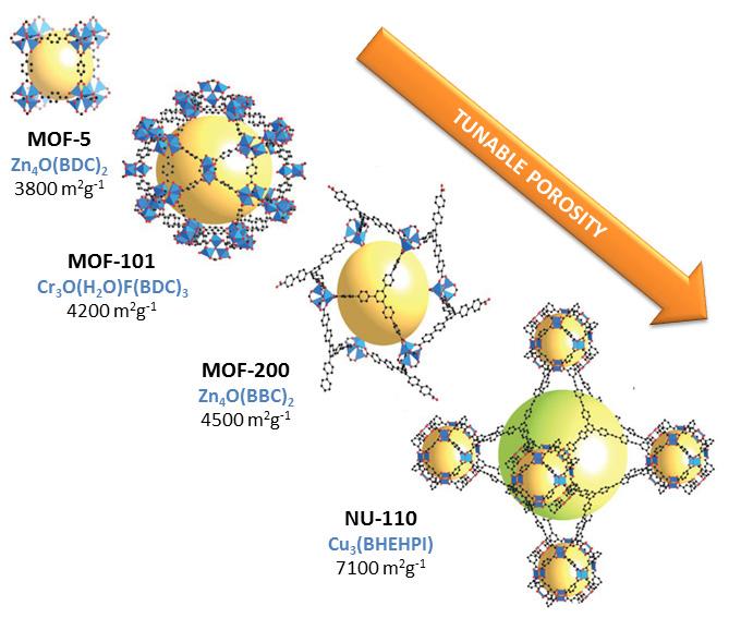
www.abc.org.uk

2002_HYDROCARBON_ENGINEERING_P04840.indd 2 2/11/2020 9:22:33 AM BELIEVINGSEEINGIS
Take a look at our ABC Certificate. It shows our circulation has been independently verified to industry agreed standards. So our advertisers know they’re getting what they paid for. ABC. See it. Believe it. Trust it.
Next steps
The promising characteristics offered by these materials will undoubtedly result in the materialisation of industrial applications of MOFs in a few years. On the road that remains to be travelled until its implementation is achieved, more efforts must be devoted to developing strategies that allow it to be obtained while minimising production costs. As for applications, further research is required to get the most out of them. More effort should be devoted to developing devices that implement these materials and unlock their full potential. Just as companies that market these materials have emerged in recent years, it would be highly desirable that we begin to see companies that implement them in the coming years.
Note For the full list of references please visit: energy-transition--references/hydrocarbonengineering.com/refining/05082022/mofs-for-the-https://www.
September 2022 HYDROCARBON ENGINEERING 36 metal sites and the flexibility of the structure increase the volumetric adsorption capacity of MOFs. The M-MOF-74 family (M = Mg, Mn, Co, Ni, Zn) has an excellent methane adsorption capacity due to its high density of open metal sites (e.g. Ni-MOF-74: 230 v/v, 35 bar, 298 K). 8 The flexible Fe(bdp) and Co(bdp) compounds (bdp 2- = 1,4-benzenedipyrazolate) undergo a structural phase transition in response to specific CH 4 pressures. 9 This behaviour allows for a higher storage capacity than has been achieved with classical adsorbents.Another application in which MOFs prove to be very helpful is hydrocarbon separation, as ethylene from ethane, and propylene from propane. These separations require high energy consumption that can be reduced with the use of MOFs. These are just a few examples of current trends in MOF research for energy applications. Their extraordinary porosity, as well as their versatility in terms of composition, structure and synthesis methods, make them excellent candidates to solve some of the challenges of the global energy transition.
Recently, the production cost of a prototype MOF, MIL-160(Al), has been evaluated. The cost of producing this material from a simulated process constructed from data collected in large-scale laboratory pilot tests was predicted to range from approximately US$55/kg at 100 tpy to US$29.5/kg for the production of 1000 tpy. 16
The development of new functional properties of these nanomaterials has grown exponentially over the last three decades. However, a crucial step for their integration into broad industrial applications is to be able to routinely synthesise these materials in large quantities and with high efficiency. Although MOF syntheses are family-specific, there are several challenges associated with most of the proposed scale-up methods: 10 n The use of organic solvents makes the process expensive and environmentally unsustainable. n Metal salts, which are typically used as precursors, can pose the significant problem of anion accumulation. n Bespoke organic ligands are sometimes required. n Particle size control. n Activation stage, as non-volatile solvents and unreacted starting materials must be removed from their Amongpores.the proposed scale-up approaches, solvent-free synthesis and water-based synthesis are the most economically and environmentally-viable strategies. 10 Solvent-free synthesis is an environmentally-friendly approach, with advantages such as speed, waste reduction, and possible continuous production. Examples are the dry gel conversion method 11 , the accelerated ageing method 12 , and the ball milling method. 13 Das et al reported the preparation of Ni-MOF-74 using the dry gel method. They obtained a yield of more than 90% in significantly less time than conventional synthesis, resulting in a 45% decrease in manufacturing cost. 11 Cliffe et al were inspired by natural mineral weathering processes to design the accelerated ageing method. They synthesised some of the MOFs of the ZIFs group from simple and cheap solid reagents using catalytic amounts of an ammonium salt under high humidity and mild temperatures (up to 45°C). 12 Conventional synthesis methods for Ni 3 (BTC) 2 ·12H 2 O (BTC = 1,3,5-benzenetricarboxylic acid) require solvents, high temperatures, and long reaction times. Using the ball milling method, Zhang et al prepared this material in just 1 minute. 13 Water is a non-toxic, cheap, readily-available and disposable solvent. As such, large-scale MOF syntheses based on this approach have a very promising future. Compared to organic solvents, water is advantageous from a post-synthetic point of view, as it is much easier to remove from the pores. To date, only a limited number of MOFs have been prepared in water, but research is growing rapidly. Didriksen et al demonstrated the feasibility of continuous flow synthesis of Ni-MOF-74 in a simple tubular reactor system at 90°C from fully-aqueous solutions of the precursors. 14 Reducing the synthesis temperature is also an important factor in terms of environmental impact and economic feasibility. Sánchez-Sánchez et al reported the water-based synthesis of MOF-5, MOF-74, MIL-100(Fe) and MIL-53–Al–X (X = NH 2 , NO 2 ) at room temperature by employing organic salts as anionic building blocks. 15
The commercialisation of MOFs is now a reality. BASF pioneered the application of solvothermal techniques on a large scale. Since then, a considerable number of companies have been created, often from research environments. Examples are MOF Technologies in the UK, NovoMOF in Switzerland, or ACSYNAM in Canada. 17
How MOFs are produced
MERYT Catalysts & Innovation c/Berlín Parcela 3F Polígono Industrial Cabezo Beaza Murcia30353-CartagenaSPAIN MERYT Catalysts & Innovation Your global supplier of catalysts, adsorbents and additives focused on new technologies and sustainable processes. Improve the profitability of your processes with MERYT catalysts and our outstanding technical knowledge, experience, and excellent service Face the Energy Transition with MERYT as your best partner to achieve your CatalystsemissionsconsumptionReduceobjectivesyourenergyandyourwithMERYTandTechnologiesinfo@meryt-chemical.com www.meryt-chemical.com +34 868 086 998 +34 670 518 438


September 2022 38 HYDROCARBON ENGINEERING

elayed coking is a thermal cracking process used in petroleum refineries to upgrade and convert petroleum residuum into liquid and gas product streams. The delayed coker is the only main process in the petroleum refinery that is a batch-continuous process. Primarily, vacuum flasher bottoms, atmospheric/distillation tower bottoms, and heavy cat-cracked oil feed the delayed coker. Since the feed stream is regularly switched between drums, a cycle of events will occur at regular intervals, depending on the delayed coking unit feed rate, drum size, and throughput capacity. The residuum feed into the coke drum is quickly heated to approximately 1000°F, and then charged into the bottom of the coke drum. It is at these temperatures that thermal cracking occurs. As the residuum sits in the insulated coke drum, it keeps cooking. The lighter streams crack in vapour form and rise to the top of the coke drum where they are drawn off to the fractionator for separation. The heavier product fills up the coke drum until nearly all of the molecules of hydrogen are cracked off. Once cooled, mostly carbon is left behind in solid form, and this is called coke. High-pressure water jets cut up the solidified coke into smaller sizes that drop out of
September 202239HYDROCARBON ENGINEERING
Tai Piazza, VEGA Americas Inc., USA, discusses the use of gamma instrumentation to improve level reliability in the delayed coking unit.
D

Neutron backscatter technology
Why is level so important?
Figure 2. Left: vessel empty – entire length of detector exposed = ‘high’ pulse rate. Middle: filling –part of detector exposed = intermediate pulse rate.
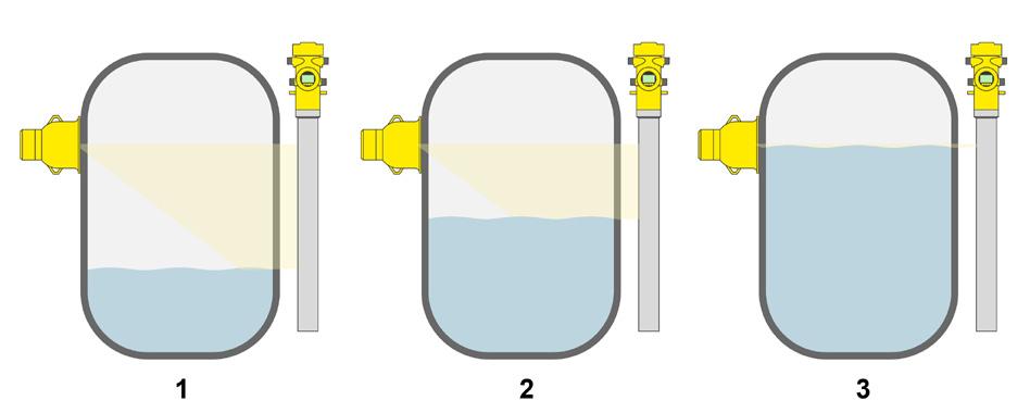
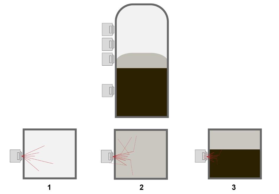
Figure 3. A gamma target switch (VEGA POINTRAC31).
the coke drum into a bunker from which the coke is loaded onto trucks, railcars, or barges for shipment. Depending on the physical structures and chemical properties of the coke, the material can be burned as fuel, calcined for use in the aluminium and steel industries, or gasified to produce electricity.
As refiners continue to process a complex mix of crude slates, including blends of sour and high-sulfur crudes, an increase of residuum is created and fed to the delayed coker. These higher sulfur crudes may produce foaming conditions that create challenges for traditional instrumentation, and thus make it difficult for operators to understand exactly where the level is within the coke drum. Ideally, operators would like to make use of as much remaining drum capacity as possible to maximise liquid yield to the fractionator. However, with foam height uncertainty, frequently filling the coke drums beyond well-established limits and time sequences can present a higher-than-acceptable risk of foam-overs or solids carryover, and pose possible safety risks. The consequences of a foam-over range from high back pressure due to plugging in outlet lines, to a required 10+ day shutdown to remove coke from the fractionator and coke blowdown system.
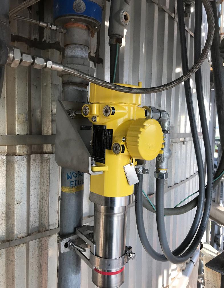
Historically, many existing coke drums included neutron backscatter (NBS) technology for point level density indication. These devices are installed onto the coke drum at specific elevations recommended by the coke drum process licensor, or prescribed specifically by the end user. These instruments transmit ‘fast’ (high energy) neutron particles into the coke drum vessel, which is approximately 18 in. Neutron radiation particles that impact hydrogen nuclei transfer some energy to that nuclei and reflect off with less energy. Some of these reflected ‘slow’ neutrons interact with a sensor in the instrument and are counted andAsfiltered.theconcentration of hydrogen increases, more slow neutrons are reflected and detected (see Figure 1). Through calibration and interpretation, the NBS detector can indicate the process state immediately in front of the device. When in proper calibration, the instruments can indicate vapour, foam, coke and water conditions (see Figure 1), and this has proven value to operational control. This is useful for prompting operators to start injecting anti-foam, switch out to the other drum, or stop quench waterWhenfeed.properly maintained, NBS technology provides operations with an effective means of level control in a very challenging process. However, the technology does have some limitations. Since these instruments are, in effect, hydrogen density gauges, they can be influenced by extraneous sources of hydrogen. This could be from rain/quench water accumulating on the device or in the vessel insulation, or from an operator or technician carrying out maintenance on the device. With direct connection to the vessel, the instrument can be exposed Figure 1. Top: general arrangement. Left: vessel empty – very little hydrocarbon, almost no backscattered neutrons = ‘zero’ or ‘low’ pulse rate. Middle: filling –hydrocarbon vapour, some backscattered neutrons = intermediate pulse rate. Right: coke present – heavy hydrocarbon, many backscattered neutrons = ‘high’ pulse rate.
September 2022 HYDROCARBON ENGINEERING 40
Right: full – none of detector exposed = ‘low’ or ‘zero’ pulse rate.
ENERGY TO REFINING Contact your representativeGracetoday. What does it mean to be part of the global energy transition? At Grace it means transforming the way we support the petroleum refining industry for a more sustainable future. Let’s collaborate on the next wave of FCC technology.

TRANSITION
TRANSFORMATION grace.com
In most level conditions, process material (including foam) completely blocks gamma rays from reaching the detector. Detector material below the process level stops producing signals to be counted, while detector material above the level continues to produce signals. As level rises, the detector’s pulse rate falls. Through a careful calibration process, the detector can be taught how to correlate measured radiation intensity (pulse rate) to process conditions such as level or density. It is important to note that gamma transmission when used for delayed coke drum levels will always track the leading edge of the process based on the aforementioned principal of operation. Additionally, one of the limitations of gamma transmission is its natural vulnerability to x-ray interference from non-destructive examination (NDE) or radiography. There are proven methods to mitigate these influences via hardware and software solutions within the instrument solution that offer operators reliability through these events.
September 2022 HYDROCARBON ENGINEERING 42 to higher-than-acceptable temperatures. As seen in Figure 1, the instrument arrangement is such that it can offer a point density indication at specific elevations, but is limited in defining level position in the areas between those elevation. When operators are trying to optimise drum capacity, this can often mean that liquid yield is not being maximised. Gamma technology and continuous level measurement Level measurements using gamma transmission have a proven track record for use in very difficult industrial measurements. First developed in the 1950s, gamma instruments for level and density have been used in the refining, petrochemical, mining, and pulp and paper industry for decades. It is in the last 25 years that gamma instruments have been used to provide coke drum level indication.Withgamma transmission, gamma rays emitted from the source holder travel towards the detector. In this configuration, the source holder and detectors are 180˚ opposed. The mass of material between the source and detector affects the number of gamma rays that reach the detector. In the case of an empty coke drum, the vessel walls block a fixed/known amount of energy. The source activity is specified in a way that allows some energy to pass through the vessel walls and reach the detector. The amount of radiation reaching the detector in an empty drum state would be quantified as the highest radiation field or maximum counts. As process material mass increases (i.e. coke level rises), more energy is blocked by the process, resulting in relatively lower numbers of gamma rays reaching the detector. When the drum is completely full, no gamma rays reach the detector, resulting in no counts. The detector counts and filters the number of received gamma rays to produce a pulse rate (or rays received per second), which is the primary measured value (see Figure 2).
Figure
In some cases, end users would like their level system to emulate the NBS functionality in respect to level indication/position. Adding gamma target switches to an existing gamma continuous level system is an excellent way to provide discrete signals for operators to recover process control. Gamma target switches can trigger anti-foam injecting, drum switch out, or quench water feed stoppage. These can be very easily mounted in the radiation beam of the existing level system and mounted directly next to or onto the continuous level devices. Both 4…20 mA HART for analog indication, and 8/16 mA HART or SPDT relay for discrete indication are available. The addition of these target switches can be an economical way to reliably improve operational control of strategic trigger actions, while providing plenty of flexibility to adjust these target switch points in the future (see Figure 3). Differences between NBS and gamma continuous NBS and gamma transmission are often utilised for common level control in the same coke drum. Intuitively, operators would expect to see the NBS indications 4. Gamma level indication vs NBS level indication.
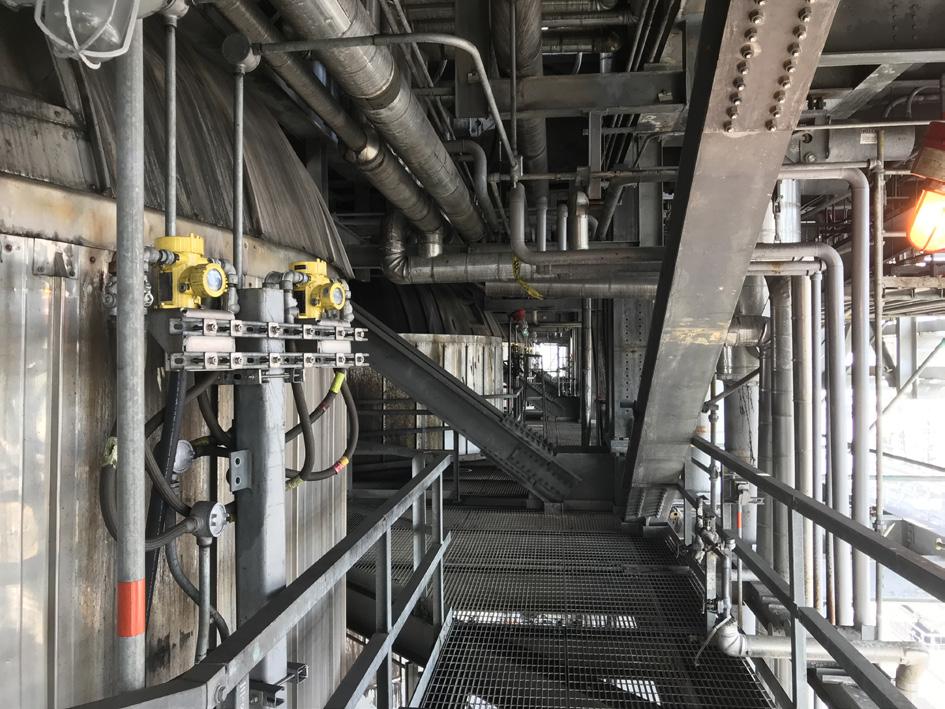
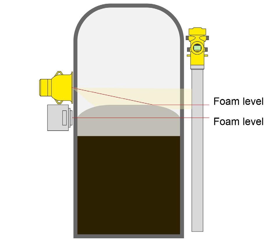
Point level
Figure 5. VEGA’s continuous level system for delayed coking.
We recover and refine precious metals from petroleum catalysts and materials used in processing from various supports, including Carbon, Zeolite, Silica-alumina, and Soluble and insoluble alumina. Also, our proprietary Pyro-Re® process o ers the only pyro-metallurgical recovery of rhenium in the industry. With it, we recover total rhenium content from spent semi-regenerative and cyclic fixed-bed hydrocarbon processing catalysts—and get you a full return. Find out more about Sabin Metal Corp’s services, operations, and why a partnership with us is the right choice at sabinmetal.com With best-in-class techniques and over seven decades of experience, we deliver the highest possible metal returns for our customers. PETROLEUM CATALYSTPETROCHEMICAL&RECYCLINGEXPERTISE

Bibliography
• ELLIS, P. J., and PAUL, C. A., ‘Tutorial: Delayed Coking Fundamentals’, Great Lakes Carbon Corp., (8 March 1998).
Process continuousopportunitiesimprovementwithgammalevel
Getting the most out of your delayed coker requires innovative solutions. High-temperature, aggressive environments make getting accurate level measurements challenging. A non-contacting continuous gamma solution does not interfere with the process. Rather, it makes it safer and allows for more efficient operation, while providing operators with improved process control (see Figure 5).
• LEFFLER, W. L., ‘Petroleum Refining in Nontechnical Language, 4th Edition’, (2008).

KFINTRODUCING774PULSAR™ CATALYSTS
Installing continuous gamma level measurement instruments will help to address a number of the deficiencies of NBS point density instrumentation. A coke drum solution using a gamma continuous level will ensure better control over this ever-changing and dynamic process. Continuous level indication will provide operators with the ability to more accurately estimate the actual level in the coke drum, allowing for the level to be safely run higher in the drum. With this additional utilisation, operators can expect to realise an additional percentage of drum filling height, which allows for increasing feed rate and utilised capacity, while maintaining the current cycle times. Using the continuous or point level outputs for automatic anti-foam control will result in less anti-foam and improve/extend downstream catalyst life. This will help to increase operator confidence and greatly reduce the risk of unplanned shutdowns.
activate at the same elevations as the gamma continuous level. However, since the measurement principal between NBS and gamma transmission is different, there is a scenario where these readings will not match. Gamma transmission is tracking the leading edge of level, regardless of density. In this way, the level reading would remain the same whether the foam is of high or low density. The NBS instruments are indicating process density, which is irrespective of the level position of the process. This would be an example of where the NBS and gamma continuous instruments would be in disagreement.Inadditionto this, during normal coking conditions, foam level is higher toward the middle of the drum due the infeed characteristics, and lower along the walls. If this foam level is high enough in the centre, there is a circumstance where the NBS instrument would not indicate density, as there is none at the vessel wall, but the gamma continuous would indicate level. This is another scenario where the NBS and gamma continuous level may not always match. See Figure 4.
KF 774 joins KF 787 in Albemarle’s growing PULSAR™ Catalyst Platform KF 774 leverages PULSAR™ active phase technology, with superior HDS/N/A activity for medium and medium-to-high pressure ULSD production. The PULSAR™ Catalyst Platform provides outstanding activity, stability and flexibility in operation for all middle distillates hydrotreaters. Albemarle delivers tomorrow’s catalyst technology solutions today. For more information, visit us online at Albemarle.com/Catalysts
W hen it comes to process heating technology, no conversation can exclude the role that liquid-phase heat transfer systems play in industrial heating technologies. Heat transfer fluids, also known as thermal oils, thermal fluids etc, are engineered fluids that are used to generate high operating temperatures at low system pressures. They are used in a multitude of manufacturing processes that require uniform, responsive heating to maintain the production of an asset. Thermal fluid systems provide years of reliable service when properly engineered and maintained. They are an economical alternative to steam and direct-fired technologies, allowing more application flexibility as well as gentle, uniform heating. While thermal fluid systems have been in use for over half a century, continuous advances in material science have paved the way for improved operational safety, capacity/capability, versatility, and reliability of these systems. This article describes some of the technology inside a typical high-temperature thermal fluid system.1 System technology Thermal fluid systems consist of one or more thermal fluid heaters, circulation pump(s), flow control valves, isolation valves, temperature and pressure gauges/sensors, and process unit operations. The primary circulation pump

September 202245HYDROCARBON ENGINEERING
Edward Cass, Paratherm Heat Transfer Fluids, USA, details the use of thermal fluid systems technology for the process heating industries.
An often-overlooked component of the heat transfer system, the expansion tank is the vessel that allows thermal fluid systems to operate at high temperatures with low pressures. The expansion tank accommodates thermal expansion volume of the oil as it is heated to operating temperature. No matter the application or equipment, this component plays several distinct roles in the thermal fluid system:
Most high-temperature systems utilise centreline-mounted cast steel centrifugal pumps with air-cooled tungsten carbide mechanical seals, water/air cooled bearings, seal flush and inerting configurations. Sealless pumps are also commonly used, particularly for service > 625˚F (330˚C) or where the thermal fluid is being operated above its normal boiling point. Sealless pumps consist of canned-motor pumps, and mag-drive pumps. These designs offer the advantage of leak free performance (low maintenance), however they are generally much less tolerant to contaminants, cavitation and dry running. In the absence of rotary joints, the thermal fluid pump is the component of the system that requires the most maintenance. The pump must be properly sized, selected and installed to provide the desired pressure, head and flow rate for efficient heat transfer and reliability. Mechanical stresses on the pump and piping should be minimised, with provisions for centreline mount designs, proper pump support, expansion joints and minimum 300# raised face ANSI flanges. The typical pressure and temperature limitations on high-temperature thermal fluid pumps is 35 bar at 400°C (500 psi at 750°F). For optimal seal performance, the seal should be kept under 204°C (350°F).
While heater design has not changed drastically in the last 30 years, combustion control technology and remote sensing technologies have been adapted to the equipment. Combustion and emission controls allow for optimised burner efficiencies, lower pollution, safer work environments, and more reliable production. Remote temperature, pressure and flow transmitters allow for real-time monitoring of system parameters from multiple access points, making anomalies easier to spot before they become bigger problems.
Expansion tank
The thermal fluid heater is the primary component of the system. It is a complex piece of equipment, comprised of a fire box, refractory, thermal fluid coil(s), burner(s), blower(s), fuel train(s), relief device(s), heating elements, probes/sensors, control panel, etc. Larger thermal fluid systems commonly employ fuel-fired heaters (natural gas, diesel, oil, biomass, etc) while small to medium sized systems may employ electric heaters. A well-designed thermal fluid heater will have optimal efficiency (combustion, power draw, etc), minimal differential between outlet temperature and film temperature, and sufficient capacity to provide temperature control over the expected operating range of the process. Liquid-tube fired heaters work on the principle of both radiant and convective heat transfer. Radiant heat transfer occurs on the flame side of the coil(s), while convective heat transfer occurs by virtue of the combustion gases passing over the coil surfaces. Depending on the heater design, more than 50% of the heat transfer may occur in the radiant zone. Serpentine coil designs are the oldest design in the industry, and consist of straight piping with 180˚ bends to form a continuous s-shape around the wall of the combustion chamber. A major benefit of serpentine designs is that the heat flux is spread over a larger surface area, minimising excessive film temperatures. These are available in both vertical and horizontal configurations.
n It ensures that the system is fully flooded, and provides adequate net-positive suction head (NPSH) to the main circulation pump. n It acts as the reservoir to accommodate fluid expansion volume as it is heated to operating temperatures. n It allows for the separation of air, water and/or volatiles from the thermal fluid. The expansion tank is typically the highest point of the system and is sized to accommodate the expansion volume to be 66 – 75% full at normal operating temperature.2 A double-drop leg arrangement allows for circulation of fluid through the tank, and is the most practical design for ease of degassing the system (separate deaerator vessels are also used). For high-temperature systems, provisions should be made for inert gas blanketing (N2(g), CH4(g), etc) to eliminate oxidation and suppress boiling of the fluid if applicable.
Thermal fluid pumps
Thermal fluid heaters
September 2022 HYDROCARBON ENGINEERING 46 moves the fluid across a heat source, capturing the thermal energy and releasing it to one or more process users downstream (reactor, reboiler, column, tank, etc) before returning it to the circulation pump. In most industrial designs, an expansion tank is piped off the return line to allow for thermal expansion of the oil as it heats up to the desired temperature.
Helical coil heaters feature one or more continuously-wound coils which frame the combustion chamber. The radiant zone of helical designs is determined by the diameter of the coil, relative to the flame. Concentric coil designs offer optimal heating efficiency by allowing for three convective zones of redirected combustion gas. In general, helical coil heaters offer the advantage of compact design, with vertical/horizontal configurations, as well as top-fired or bottom-fired burners. Electric heaters are available in numerous configurations and capacities. Cabinet style heaters are self-contained units with the heater, circulation pump, controls, valves, and expansion reservoir all inside the cabinet. Cabinet style heaters have low to medium thermal capacities, but offer excellent operational flexibility. Circulation heaters typically have higher capacities vs cabinet style, and are often sold as integrated skid-style systems complete with pumps, expansion tank, valves and controls. In both designs, the fluid is circulated past the heating elements, which should be carefully designed such that watt density does not exceed 25 – 30 W/in2. Depending on the application, electric heaters may offer better economics vs fired heater designs.
Hit us with your nasty fats or sling some waste oils our direction. We’ll put on a show for even the rowdiest of feedstocks. For years, our proprietary ActiPhase® active filtration technology has been a proven performer in the world’s biggest renewables venues. Ready for an encore? Rock on! Optimize crystaphase.com


In the heat transfer industry, synthetic fluids are also known as ‘aromatics’ since they are benzene-based chemistries. These fluids tend to have narrow boiling ranges vs their mineral oil cousins, so operation in both the liquid and vapour phase is possible. Synthetic aromatic fluids can offer many benefits over conventional mineral oil-based fluids, such as enhanced thermal stability, better low-temperature performance, wider operating ranges, and longer drain intervals. These fluids tend to be more hazardous in terms of handling, disposal, and environmental impact, and are typically two to three times more expensive than mineral oil fluids. There are a wide range of synthetic heat transfer fluids available on the market, but there are fewer suppliers of these specialty fluids. Table 1 highlights the most popular synthetic varieties that are in use globally. For these fluids, maximum temperature, boiling point, and vapour pressure vary widely, and many of these fluids are suitable for operation in both liquid and vapour phase. Cost generally increases with performance, so fluids that can operate at temperature extremes or over a wide operating range tend to be more expensive. Temperature ratings for all heat transfer fluids
Table 1. Typical properties of the most commonly used synthetic heat transfer fluids Synthetic fluids in heat transfer Temperature range (°F) Vapour pressure at temperaturemaximum (psia) Boiling range (°F) terphenylHydrogenatedblends 25 – 650 Below atmospheric > 700 Diphenylethane blends -40 – 650 > 50 < 525 Diphenyl oxide/ biphenyl blends 60 – 750 > 100 < 500 Dibenzyl toluene blends 25 – 660 Below atmospheric > 700 Alkylated biphenyls -25 – 660 Below atmospheric 600 – 700 Diaryl/triaryl ether blends 10 – 715 > 20 < 600 Alkylated benzene blends -15 – 575 Below atmospheric > 600
A fully-instrumented expansion tank might include inert gas pressure/back pressure regulators, pressure control valves, pressure relief valves, pressure gauges, manual vent(s), low and high-level switches/interlocks/alarms, drain valve(s), and relief and drain piping. During the design phase, careful consideration should be given to the expansion and drain plans. The addition of low-point drain valves, isolation capabilities, and appropriate drain and discharge containment goes a long way when the system inevitably needs to be drained.
Fluid technology
n Group I: base oils with a viscosity index3 of 80 – 120, and containing less than 90% saturated hydrocarbons and/or more than 0.03% sulfur.
Mineral oil heat transfer fluids
n Group II: base oils with a viscosity index of 80 – 120, and containing at least 90% saturated hydrocarbons and no more than 0.03% sulfur. n Group III: base oils with a viscosity index of 120 minimum, minimum 90% saturated hydrocarbons, and maximum 0.03% sulfur. Mineral oil heat transfer fluids derived from all three groups are available from various suppliers. The least expensive fluids on the market are Group I based, but these are generally considered inferior to Group II and III type fluids due to lower thermal stability and higher fouling potential. It is important to note that mineral oil heat transfer fluids are distinctly different formulations to lubricant oils. All of these oils have some similarities in base oil composition, but many commonly-used lubricant additives such as extreme pressure and anti-wear agents (EP/AW), defoamers, demulsifiers, viscosity index improvers, corrosion inhibitors, etc are not rated for the high temperatures experienced in heat transfer systems. A number of additive chemistries tend to foul heat exchange surfaces or may decompose into reactive species that can catalyse fluid degradation. For this reason, it is important to specify a heat transfer fluid from a reputable supplier offering fluids that have been specifically formulated for heat transfer service. If the supplier cannot provide thermal property data over the operating range of the fluid, it is likely that the fluid is not ideally suited for heat transfer service.4
September 2022 HYDROCARBON ENGINEERING 48
The chemistry of a given heat transfer fluid dictates its specific physical properties and operating range. Historically, heat transfer fluids have been divided into two categories: mineral oil-derived (organic hydrocarbons), and synthetic hydrocarbons. Mineral oil is a catch-all term, which includes different grades and purities of paraffinic oils, naphthenic oils, and blends thereof. Synthetic is also a catch-all term, collectively accounting for benzene-derived fluids with favourable heat transfer characteristics. Mineral oil fluids are generally considered cost-effective robust choices for applications operating to a maximum 288 – 316°C (550 – 600°F), though some high-grade organics are suitable to 332°C (630°F) provided the heat flux is sufficiently low. Synthetic fluids are generally more expensive, but can provide fill-for-life performance in the mineral oil operating range in a well-designed and maintained system. Synthetic fluids are usually the obvious choice when operating above 316°C (600°F), and tend to be superior in terms of low-temperature performance.
Mineral oil heat transfer fluids (aka ‘hot oils’) are those formulated from the base oils produced in refining processes. The American Petroleum Institute (API) classifies petroleum base oils into three groups:
Synthetic heat transfer fluids
n System engineering complexity n Narrowed
n
vs
n Handling
Cons n Limited
n
4. Thermal property data includes density, viscosity, thermal conductivity, heat capacity, and vapour pressure over the recommended operating range.

n Regional
Notes 1. The scope of this article refers primarily to liquid-phase heat transfer systems. 2. Liquid phase hydrocarbon fluids have expansion rates of 3 – 7% per 100°F depending on the chemistry.
compatibility n Narrowed
n Often
n Low
should be set based on laboratory tests and established field performance.Thereare a handful of other synthetic chemistries used for more niche applications such as silicones, cycloalkane blends, polyalkylene glycols, fluorocarbons, esters and polyalphaolefins, to name a few. Since their use is limited to special applications, they are not discussed here. Table 2 summarises the pros and cons of mineral oil and synthetic fluids.
n High
n Insoluble
WE’RE IN YOUR INDUSTRY
3. Viscosity index is a unitless measure of the change of viscosity with temperature, commonly associated with lubricating oils.
Table 2. Summary comparison of mineral-oil and synthetic heat transfer fluids Fluid type Mineral oils Synthetics Pros Cost effective Capable to 630˚F Low vapour pressures High boiling points High flashpoints friendly/low toxicity to no regulatory restrictions material compatibility grade available thermal stability Capable to 750˚F performancelow-temperature solvency phase degradation byproducts flash and autoignition efficient mineral-based performancelow-temperature to moderate solvency degradation byproducts boiler accumulation formulatedre-labelled/improperly fouling tendency efficient aromatics and disposal regulatory restrictions have high vapour cost mineral-based material supplier
Conclusion Liquid phase heat transfer systems are critical production assets that must be properly designed, installed, and maintained for reliable performance. They consist of several key components, each with their own technology, specifications, and performance parameters. The components and technology discussed in this article are overviews and are in no way an exhaustive treatise of a typical high-temperature heat transfer system. Materials science and the digital transformation will continue to provide robust technologies for safer and more reliable operation of heat transfer systems.
n Low
Paratherm is the premier heat transfer fluids provider for over 30 years. Our extensive fluid analysis program delivers results driven benefits that we are proud of.
n
vs
n User
n High
n
n Good
n Vapour
n Food
operation n Soluble
n
n High
n Less
n Broad
temperatures n More
n Higher
vs
pressure n Higher
n Little
options
n
n Can
www.globalhydrogenreview.com A focusedmagazinenewon the global hydrogen sector The Autumn issue of Global Hydrogen Review is out now Subscribe for free:


T he digitalisation of plant data is a key component to operating a process plant. However, how the plant data is handled plays an important role in the Industry 4.0 initiative. Digital transformation is not only about digitalisation, as it is an organisation-wide effort to radically change the work process by implementing a system that: n Fits within the existing workflow and can be adopted without any disruption. n Promotes collaboration between work groups and enhances productivity. n Provides agility. As an example, Figure 1 illustrates how several HTRI software tools connect within each other, with plant data, and with end users – all through a digital platform. A physical asset (see Figure 1) can be a single heat exchanger, a network of heat exchangers, furnaces, connected pumps, valves, etc. A digital equivalent of the asset is created using HTRI software tools. The data transfer between the data historian and the digital model is fully automated, creating the digital twin of the system. Having a standard set of tools facilitates work groups (individuals, groups or departments), geographically located anywhere, to collaboratively interact with the E. M. Ishiyama, J. Kennedy, S. J. Pugh and H. U. Zettler, Heat Transfer Research Inc., explore how successful digital transformation is helping ENEOS Group refineries in Japan to eliminate waste, reduce lost time in data processing, and facilitate collaboration between different work groups within the organisation.
September 202251HYDROCARBON ENGINEERING

Figure 3a is a plot of change in furnace inlet temperature (FIT) over time, including four sets of data. The first set of data illustrated by the dashed line marked ‘No cleaning’ is the FIT profile obtained when no cleaning actions were performed. Above this, marked ‘Case 1: Original expected trend’ shows an approximately 10°C increase in FIT when following the cleaning actions that were initially proposed at the plant. The proposed SmartPM cleaning sequence in Case 2 shows a further 5°C increase compared to Case 1. After the plant followed the cleaning schedule in Case 2, the FIT profile was obtained, shown in the scattered data marked ‘Plant data after cleaning’. When the plant operation reached steady state following the disturbance after cleaning, it was possible to observe that the actual FIT trend followed the software’s prediction.
SmartPM enabled the Marifu refinery to significantly reduce the associated workload, for cleaning optimisation. The conventional cleaning method combined chemical and mechanical cleaning over three cleaning events involving the cleaning of 20 shells. Analysis showed that the conventional cleaning method was less beneficial than the SmartPM proposed cleaning schedule, which included the mechanical cleaning of 10 shells over four cleaning events. The benefit achieved was both in terms of improved energy recovery, as shown in the area plot comparison of FIT over time, and the reduced number of cleaning events (see Figure 3b).
Flow split optimisation at ENEOS Group Osaka refinery
September 2022 HYDROCARBON ENGINEERING 52 digital twin models to make operational, engineering, financial and environmental decisions. For example, operators looking at real-time optimisation and fouling mitigation may work on collaborative projects at the same time as a maintenance group looking into heat exchanger restoration, and with an engineering group who are looking into OPEX and CAPEX projects. This article provides a summary of a successful digital transformation at ENEOS Group refineries in Japan. Digital transformation ENEOS Group refineries used SmartPMTM for refinery-wide digital transformation.1, 2 The group is the largest crude oil refiner in Japan, with 11 refineries located across the country (see Figure 2). SmartPM has been used to construct 13 heat exchanger network models for the Group’s refineries, 11 of them being the crude preheat train. Over 30 SmartPM model users across the company utilise the tool for performance monitoring and process optimisation, including: n Monitoring fouling. n Fouling prediction. n Flow split and cleaning schedule optimisation. n Evaluation of antifoulant usage. n Evaluation of retrofit and revamp projects.
The Group’s Negishi refinery had a cleaning plan before utilising SmartPM (see Figure 3a, Case 1). The software allowed for the generation of a list of heat exchangers and combinations of heat exchangers to clean on a specific date in descending order of the energy benefit, accounting for the network interaction of cleaning a heat exchanger on the entire network thermo-hydraulics. Case 2 (in Figure 3a) discusses the cleaning plan at the refinery, as re-evaluated using SmartPM. Ultimately, the refinery monitored its operation to validate whether the digital model accurately predicted the real performance.
Figure 1. Schematic workflow connecting physical assets to equivalent digital twin models via HTRI technology.
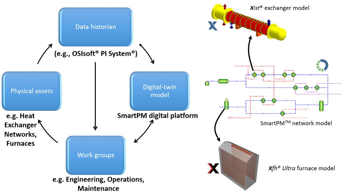
Figure 2. ENEOS Group locations across Japan utilising SmartPM digital twin models.
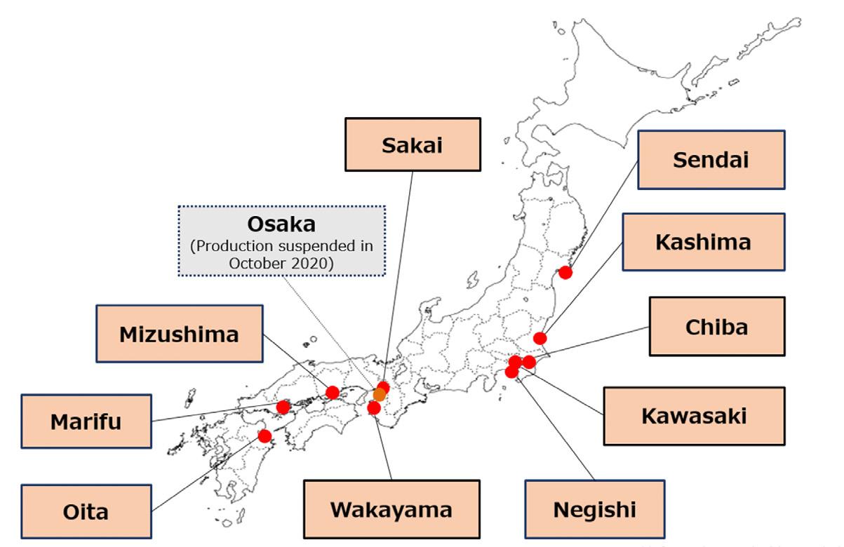
Evaluation of different cleaning scenarios
Figure 4a is a simple illustration of a section of the preheat train at the Osaka refinery. The crude preheat train divides into three parallel branches following a preflash. The original operation was to maintain equal outlet temperatures of the three parallel branches by adjusting the flow splits (which were set at 63%, 19% and 19%). The SmartPM optimisation
Together with Advanced Refining Technologies LLC, CLG offers the most complete portfolio of hydroprocessing catalysts in the industry. We offer more experience than any other licensor providing leading technologies, expertise, and innovative solutions for refiners worldwide. To get the performance and flexibility needed to keep pace with changing market dynamics, start by visiting www.chevronlummus.com.

SPECIALIZED CATALYSTS

AND
JOINTLY DEVELOPED SOLUTIONS FOR CLEANER FUELS MAXIMUM PERFORMANCE
September 2022 HYDROCARBON ENGINEERING 54 study identified the best flow split to maximise the mixed FIT temperature, resulting in a 44, 27, 29% flow split.


Antifoulant usage optimisation at the ENEOS Group Osaka refinery
At the Osaka refinery, antifoulants are used on a daily basis, and different antifoulants are used over specific periods. Evaluating the impact of antifoulants was not straightforward, given the dynamic variation in operating conditions. The changes in operating conditions are not limited to changes in flow rates and temperatures but also involve changes in valve openings, exchanger bypasses, exchangers being offline, etc. SmartPM was used to perform data reconciliation and fit ‘dynamic fouling models’ for the crudes for periods when different antifoulants were used.Dynamic fouling models are used to predict fouling under changing operating conditions. The fouling model is defined for a stream. Fouling is a function of the stream chemistry, which is the type of crude/antifoulant blend, operating conditions that represent the changing surface temperatures and flow parameters within units, and the metallurgy of the surface (such as if the unit is CS, SS, special alloy, etc). A detailed description of the dynamic fouling models is presented elsewhere. 3, 4 For each antifoulant/crude blend, the tendency of fouling (quantified by the fouling propensity factor) is identified through fouling model analysis utilising historical exchanger operation. Past performance is simulated using the fitted fouling model for model validation prior to performing prediction studies. The result is the fouling prediction superimposed on top of the historical fouling resistances for all exchangers. Two examples shown in Figure 5a represent periods when two different antifoulants were used. These plots of fouling
Figure 4. A schematic of the post-preflash section of a preheat train with three parallel branches (left). Original flow splits of 63%, 19% and 19% were changed to 44%, 27% and 29% in the study. FIT profile before and after monitoring flow split optimisation (right).
Figure 3. Comparison of FIT at the Negishi refinery preheat train for different cleaning strategies (a). FIT profile comparing the conventional and optimised cleaning process at the Marifu refinery (b).
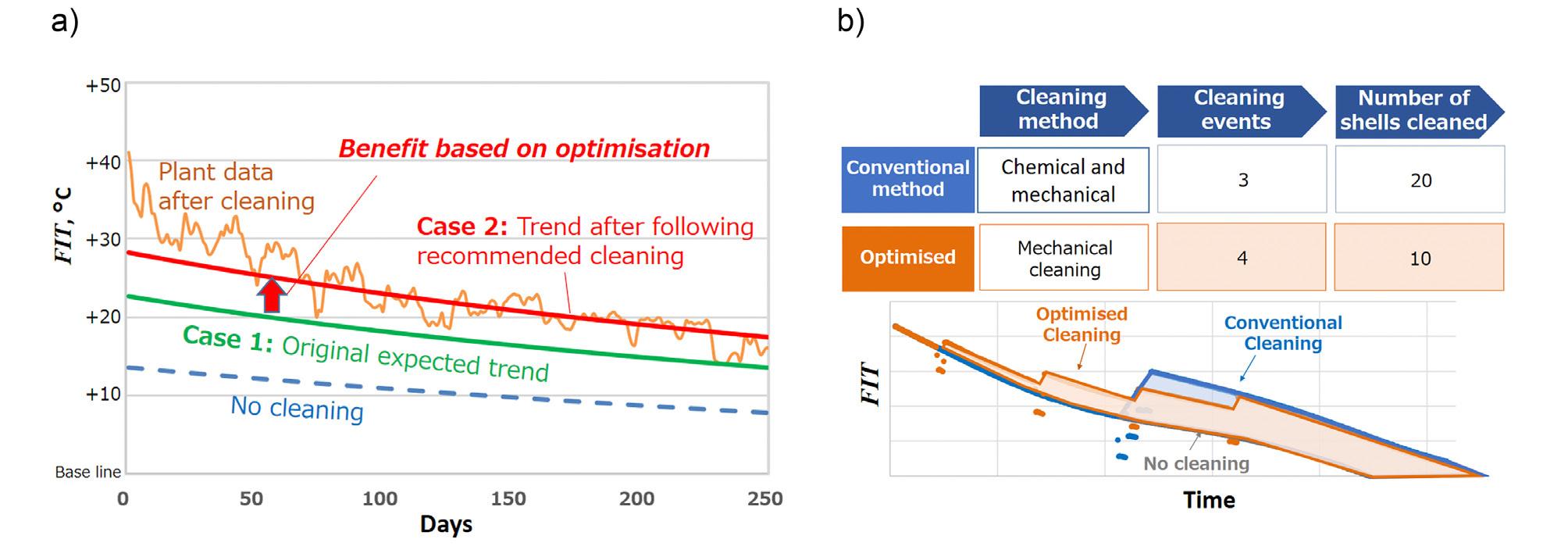
Figure 4b shows the FIT variation over time. The bottom line shows the FIT trend under conventional operation. The optimised line, which is 1.5°C above the conventional line, shows the optimised performance. It is also observed that the monitoring data that was obtained following the flow split optimisation followed the SmartPM prediction.
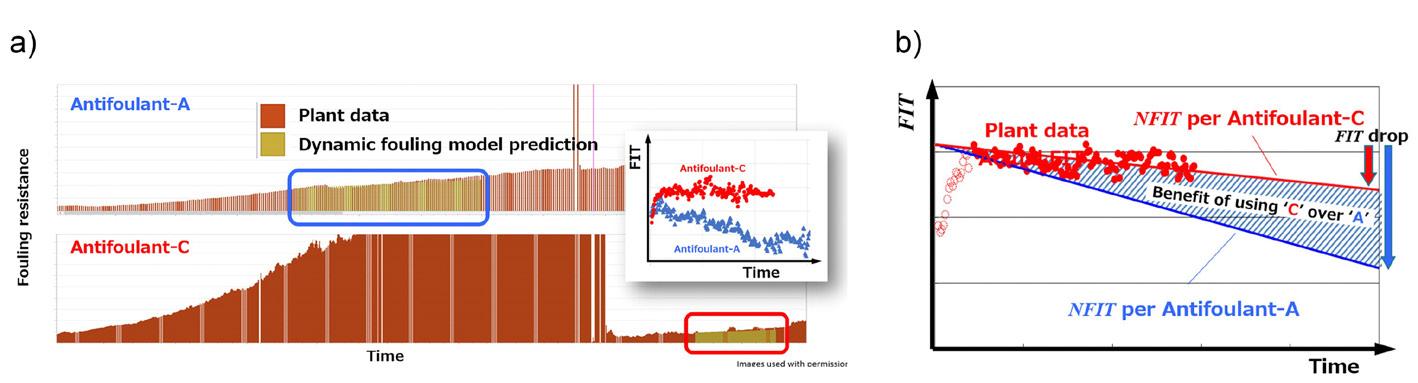
Figure 5. Predicted fouling prediction superimposed on monitored fouling resistance profile for two exchangers and two periods when two different antifoulants were used (a). Comparison of FIT for different antifoulant usage (b).
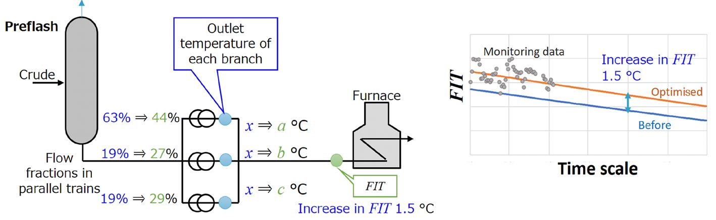
resistances change over time, and it is visible on the FIT plot that the different antifoulants affect how fast the FIT drops, which is related to the fouling resistance changes for each unit.
2. ISHIYAMA, E. M., KENNEDY, J., OAKLEY, D., ZETTLER, H. U., and PUGH, S. J., ‘Fouling Management through Digital Transformation’, 14th International Conference on Heat Exchanger Fouling and Cleaning, Wagrain, Austria, (2022).

3. WILSON, D. I., ISHIYAMA, E. M., and POLLEY, G. T., ‘Twenty Years of Ebert and Panchal What Next?’, Heat Transfer Engineering , Vol. 38, No. 7 – 8, (2017), pp. 669 – 680. ISHIYAMA, E. M., JUHEL, C., AQUINO, B., HAGI, H., PUGH,
Conclusion The importance of digital transformation has been illustrated in this article through several examples from ENEOS Group refineries. Conventionally, many of the studies involving conventional cleaning, use of additives such as antifoulants, optimising operations such as flow splits, and CAPEX-heavy projects had to be carried out independently of each other. Digital transformation tools are perceived to open possibilities by performing systematic combined optimisation analyses, identifying the overall impact on the network level, while incorporating individual operational strategies and technical constraints. References 1. OKADA, T., ‘Digital Transformation of Crude Preheat Train Fouling Management through SmartPM’, 46th Refining Panel Discussion Meeting, Japan, (2022).
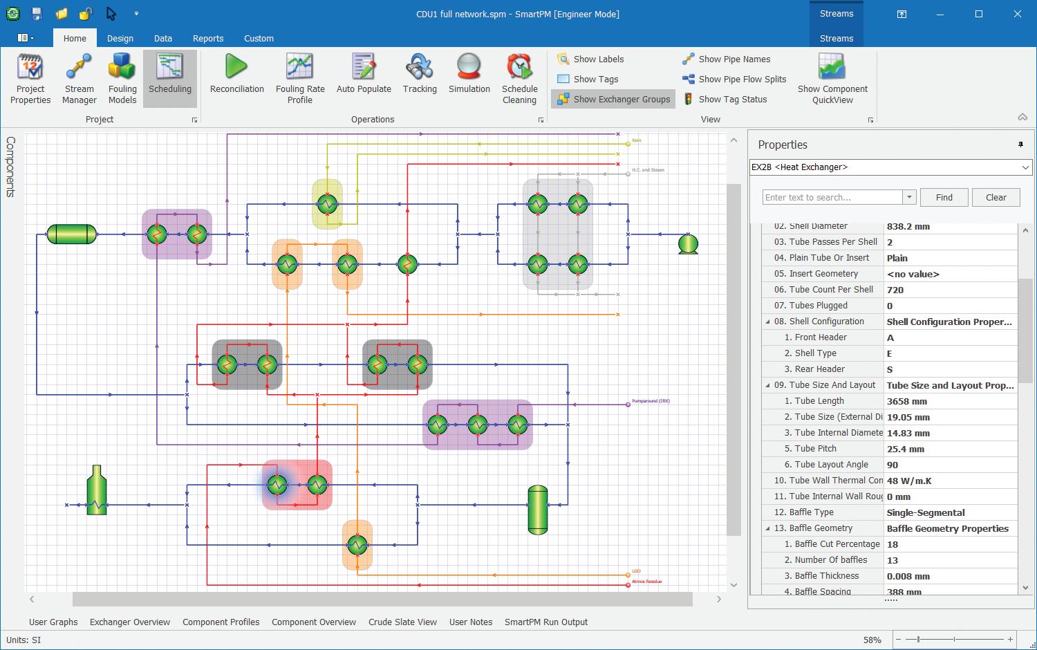
Table 1 shows the summary performances of three different antifoulants (A, B and C) based on the drop in FIT over time. Figure 5b shows the FIT variation over time for three sets of data. The steepest line, marked NFIT per antifoulant A, is the prediction of FIT under a normalised condition (i.e. at a fixed stream temperature and flow inlet conditions). The NFIT per antifoulant C indicates the prediction of the FIT drop using antifoulant C under the same normalised condition as antifoulant A. The plant data show the actual FIT drop using antifoulant C, which follows the prediction. The difference in FIT drop, in this case using antifoulant C, is a drop of only 7.8°C compared to 19.1°C, resulting in a maximum viable cost that can be paid for using a certain antifoulant compared to another.
Table 1. Summary of three different antifoulants and evaluated drop in FIT over a specified period Antifoulant Drop in FIT (°C) A 19.1 B 17.3 C 7.8 SmartPMHalfPgResize_final.pdf 1 8/9/22 12:25 PM

There are two possibilities: n Reliability strategy related content is changed, informally, without overview, analysis, review, and approval. n Reliability strategy related content is not changed at all, because the process is so rigid.
September 202257HYDROCARBON ENGINEERING
Jason Apps, ARMS Reliability, Australia, discusses how Asset Strategy Management is key to the successful digital transformation of the downstream oil and gas sector.
An organisation’s reliability strategy should be evolving constantly for a range of reasons, such as: n A change of operational context. n Changes in market conditions. n Equipment ages. n Technology changes. n Fixed cost changes. n Organisational priorities change.
T he principles and tools of reliability centred maintenance (RCM) have been around for decades, yet many organisations are struggling to effectively put these principles into practice and make reliability a reality. Today’s reliability managers understand the key elements of a sound reliability programme: avoiding unexpected failures, outages, safety exposures and costs. They invest time and money into creating asset maintenance strategies, but often fail to implement and execute the strategies effectively. There is no process for reliability strategy review and updates, or, even if there is, what is usually missing is any kind of trigger to start the review process. The outcome of these typical environments is underperforming assets. This will likely have the associated problems of high costs and unknown levels of risk. Ultimately, the organisation is not in control of the asset.
There is no governance of the reliability strategy decision and related content.

n They can be easily updated, customised for site variations, and redeployed with ease.
September 2022 HYDROCARBON ENGINEERING 58
Core elements of ASM
n They continually evolve based on real data and an effective review process.
n Tactical plans: the maintenance plans that will be executed. This includes the tasks to be performed, when they are done, how they are done, who does them, and the materials required.
ASM can be simplified into three main phases. Breaking down the process into these core elements, as shown in Figure 3, works for both initial implementation and ongoing ASM. Build The first phase covers setting the structure for reliability strategy and developing baseline, optimal reliability strategies for each equipment type for a given asset criticality. Structured correctly, ASM offers a perfect platform for consolidating data and ensuring a single instance of each piece of reliability strategy content.
n Asset/fleet: the decisions made at an asset level, such as major component or asset replacement ages, or major shutdown or system outage schedules.
n Portfolio: optimisation of budget allocation for a portfolio to maximise value, given the financial and resource constraints.
Figure 2. How risk changes over time if reliability strategy content is fixed.

Figure 1. How risk exposure changes as reliability strategy content is updated over time.
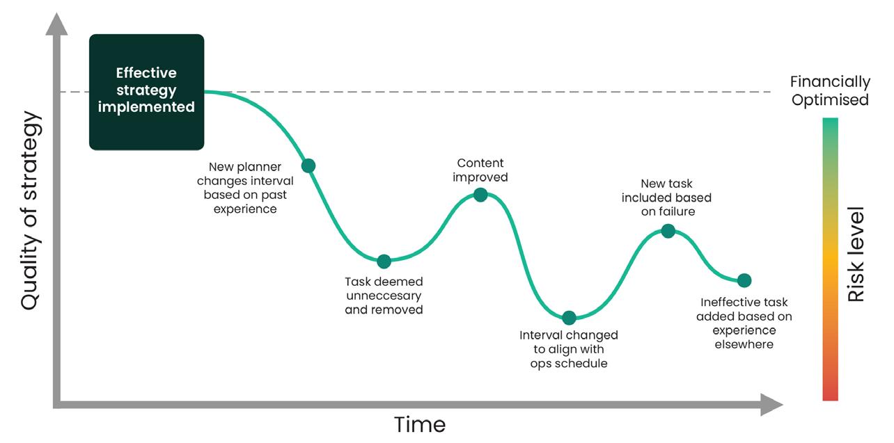
n The best strategies, developed by the best subject matter experts (SMEs), are in place.
What does managementstrategycover?
n They are deployed to all assets, all of the time.
In environment one in Figure 1, the reliability strategy is changed informally. It is likely not changing at all in alignment with the changing environment. This leads to an unknown and potentially undesirable level of risk. The environment in Figure 2 illustrates that the reliability strategy rarely changes, mainly because of the difficulty. It certainly does not remained aligned with the changing environment. The staggering reality is that most organisations do not know the level of risk with which they are operating, based on their existing reliability strategies. The unplanned failures still being experienced are not unforeseeable, and most could and should be addressed by a reliability strategy that is dynamic and always aligned to the changing operational environment. Reliability strategies demand constant refinement and adjustment to ensure that they are always improving and delivering the optimal balance of risk, cost and performance.
What is ASM? Asset Strategy Management (ASM) is a holistic, consistent and standardised approach to managing asset strategies organisation-wide. Physical assets and independent plants/sites are connected to a central system, allowing for the effective development, implementation, maintenance and optimisation of asset strategies. Implementing an ASM programme ensures that optimal strategies are always deployed, quickly and efficiently, resulting in the reduction of failures, downtime and risk, and consequently a lower cost of operations.Aswith work execution management, ASM is a business process that describes how the maintenance plans are managed over time so that they continue to provide the desired balance of risk, cost and asset performance. The process identifies trigger points to engage with, and accountabilities for analysis, review and approval; and requires a technical solution to support the process. ASM delivers performance improvement continually as data becomes available. In short, ASM means that:
In the refining industry, market conditions are always evolving with new regulatory requirements, global demand shifts, and the use of heavier feedstocks among other factors.

Contact your ART representative today for more information. arthydroprocessing.com
ART is a joint venture of Chevron and W. R. Grace & Co., created to bring you state-of-the-art hydroprocessing catalyst solutions for petroleum refining applications worldwide. We collaborate with the industry’s leading licensor, CLG, to provide complete solutions to address your needs to extract more value from every barrel of oil. Combined with our unparalleled technical customer service, we deliver results for you.
ART Hydroprocessing can help you take a better perspective on these challenges based on our deep understanding of refinery operations and a full spectrum of hydroprocessing catalysts solutions that maximize profits by balancing run length, severity, feed flexibility, contaminants, and operating constraints.
A Better Perspective on Hydroprocessing Solutions
It is not uncommon for organisations to have tens or hundreds of thousands of assets, and a corresponding number of strategies. What organisations do not have is the time or resources to regularly review and optimise those strategies – at least not in a traditional manner. With an always-on ASM, process strategy review and optimisation has never been more efficient. Another challenge is that organisations lack a formal process to trigger or manage strategy reviews. As such, there is no mechanism to kickstart the strategy review and no way to identify which assets the reliability team should focus on. In these cases, a reactive maintenance culture can set in where people are more focused on fixing failures than trying to prevent them.
Lack of access to SMEs
Figure 3. How risk changes over time if reliability strategy content is fixed.
Once baseline reliability strategies have been created for each asset type, they need to be deployed to the actual asset listing of hierarchy. There are four main components of the deploy phase:
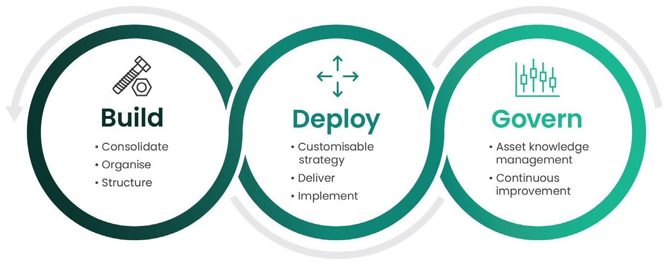
n A lack of guidelines and requirements that support consistent master data.
Failure to implement When RCM first began to hit its stride, organisations were quick to invest in the task of developing maintenance strategies. But, according to research, 66% of corporate strategy is never implemented.1 One of the issues here is that not all organisations have a line of sight into the field to know whether strategies are being implemented. Even if they are implemented, this is really just the firstThestep.dynamic nature of the operating environment means that organisations need to frequently adjust their strategies to account for things such as changes to performance targets. They also require good governance to ensure that strategies are implemented in a consistent manner and are not changed without a formal review.
Deploy
n Gather feedback of master data keys.
September 2022 HYDROCARBON ENGINEERING 60
n Package the maintenance tasks into the agreed master data structure and implement into the Enterprise Asset Management (EAM) system.
n Use the baseline strategies and account for any different operating context and environmental conditions.
Challenges that ASM solves For reliability managers that are already busy putting out day-to-day fires, this can present a number of challenges. Many of these challenges relate to their inability to leverage data, and specifically reliability content, across organisations. This compounds the time that it takes to build, deploy and manage strategies, and can result in ad hoc strategy development where changes are made without any structure, consistency or justification.
n A lack of, or inefficient, data governance procedures to mandate the capture and recording of specific data.
Unstructured data Large, multi-site organisations share a common challenge in that data is fragmented across many sources, restricting visibility into potential improvements, and complicating things such as the comparison of similar assets and plans.
n Inconsistent asset hierarchy driving different maintenance plan structures for similar equipment.
Sustain Now that the reliability strategies have been deployed enterprise-wide, another key aspect of the ASM process is to sustain the integrity of the strategies. Governance of asset reliability strategies assures compliance and drives continuous improvement of the maintenance plans employed across all assets.
n Strategy development or review processes that are disconnected from the master data generation process. Implementing ASM can help to rectify these challenges by providing a process and system that centralises data.
Reliability, particularly at a site level, often relies heavily on SMEs. However, what happens when those experts leave and take their knowledge with them? With an ASM process and system in place to capture strategy-related content, important knowledge can be retained when experts leave. This includes insight into past strategy-related decisions that can inform future improvements. It is also critical to maximise the available time from SMEs who are typically in demand. The right structure to asset review and data collection and refinement is key to ensuring that the work is completed in an efficient but effective way. Of course, capturing the knowledge of the best SMEs is not only important in case they leave; it can also allow for that knowledge to be available for all to use. For example, if an optimal strategy is defined for an asset at one site, it can be leveraged across all others.
Pressures on time and resources
Specific data challenges include:
n Forecast the performance of the reliability strategies.
On Demand Webinars Explore our library of coveringOnfree-to-accessDemandWebinars,arangeoftopics in the downstream sector Visit: www.hydrocarbonengineering.com/webinars


ASM helps the achievement of the optimal balance of performance, risk and cost. It significantly reduces spend on reactive maintenance, ensures assets are not over maintained, and carries a lower risk with fewer accidents. All of this leads to an overall reduction in maintenance spend, and a more assured way to manage maintenance budgets.
With an ASM process and component strategy library, maintenance strategies are built using generic templates, and strategies are easily shared across similar assets. The system seamlessly integrates with an EAM system to ensure data accuracy, and allows for the electronic deployment of asset strategies. Time is no longer spent with inefficient processes and duplicating work.
The maintenance strategies executed are one of the single biggest contributors to asset performance. ASM ensures that the best strategies are applied to all assets across all sites, and provides data-driven intelligence to continually improve upon those strategies. The result is less time spent in reactive maintenance mode and more time delivering the highest value to the organisation.
Clearly only one (if any) of those strategies can be the optimal strategy, and much time is wasted by different sites designing different strategies for like assets. The opportunity to rapidly make a change to an asset strategy, based on new information, is also lost when there are dissimilar strategies on similar assets. This translates to lost opportunity, as any improvement initiative is deployed on only one asset, instead of the entire asset base.
Leverage key learnings Digital connected reliability strategies, which form the foundation of the ASM process, ensure that the source of the routine tasks on each asset is known, as it relates back to the corporate baseline reliability strategies. The variations are also recorded, and are easily visible at all times. This structure allows for any key learnings or improvements to be implemented locally, and instantly assesses deployment to all other assets across the entire asset base to utilise the same baseline reliability strategy, while being mindful of local variations that have been made. Practically speaking, this also translates to any improvement initiative, which is determined to be effective for implementation based on a review of a specific component. The improvement can be immediately assessed for all other instances of that component in the same area, the same site, or all sites within the same country or across an entire global asset base. ASM is a vehicle to deploy asset-wide improvement initiatives and key reliability strategy developments that would otherwise not be possible, in just few clicks.
Faster strategy development
Key business benefits of ASM
When maintenance strategies are changed without approval or maintenance intervals, and the tasks executed differ from the agreed strategy, operators can be exposed to significant risk. ASM minimises risk through workflow management, where unauthorised strategy changes (and risks) are eliminated.
Reduction in reactive maintenance
Leveraging the value of ASM
To reap the benefits of reliability, the best strategies need to be in place across all assets at all sites. However, this is almost impossible to achieve without a scalable process. Instead, organisations often end up with multiple strategies for the same asset type, even when those assets are performing the same duties under the same conditions.
It is the combination of the key design principles of the ASM process that provide value, both in terms of the productivity of the reliability and maintenance function, and the ability to leverage key learnings and improvements across the entire organisation.
Conclusion ASM ensures that the asset care plan is always in alignment with current operating context, environment, asset age and condition. Along with the asset condition monitoring (ACM), asset defect elimination (ADE), and EAM functions, ASM forms the foundation for world-class APM. Reference 1. JOHNSON, L. K., ‘Execute Your Strategy - Without Killing It’, Harvard Management Update, (2004), pp. 3 – 6.
September 2022 HYDROCARBON ENGINEERING 62
Inability to scale process
Difficult to create an enterprise view For organisations using spreadsheets to manage asset strategies, it is common to have a different spreadsheet at each site. This limits the ability for organisations to leverage best practice across sites, and makes it difficult for leaders to achieve a consolidated view of what is happening across the enterprise. This lack of visibility ultimately impacts decision making and makes it difficult to prioritise resources to manage cost and risk.
Risk reduction
Reduced maintenance spend
Productivity
Improved performance
With the ability to manage reliability strategy review, approval, and updated with digital workflows, as well as digital reliability strategy content and rule-based maintenance task packaging and implementation, productivity gains to an organisation are significant. The concept of ensuring that reliability strategies are aligned to the current operating environment becomes automatic, dynamic and efficient. Most of all it leads to a true data-driven decision making environment.
ASM removes inconsistencies from asset strategies to ensure that assets are running at their full potential, enterprise-wide. With ASM, operators can easily align maintenance strategies to operational and service level targets, and deliver bottom-line results.
The Future of Energy: Sustainable, Affordable, Secure Strategically taking place before COP27, ADIPEC is the global platform for leaders to reinforce commitments that will drive the industry towards reducing emissions, meeting decarbonisation goals, and providing a realistic view on short- and long-term energy outlooks. Supported By 31 October - 3 November 2022 Abu Dhabi, United Arab Emirates Strategic Conference View the Strategic Conference Programme www.adipec.com/strategicprogramme Innovation and the energy transition: pioneering a new era of technology development The road to COP27 and COP28 The long-term impacts of geopolitics on the global economy and energy industry The new management agenda: future workforce and the leaders of tomorrow An industry transitioning: adapting to the new fundamentals of supply, low carbon and new energy solutions • Offshore & Marine Conference • Strategic Conference • Forum for Diversity, Equity & Inclusion Conference • Downstream Technical Conference • Smart Manufacturing Strategic & Technical Conferences • Technical Conference STRATEGIC CONFERENCE THEMES: CONFERENCES AT ADIPEC: • Decarbonisation Conference NEW GoldPartnersSponsors PartnerVenueHostCity StrategicPartnerInsights TechnicalOrganisedConferenceByOfficialPartnerHotel ADIPEC Brought To You ByDecarbonisationZonePartner HydrogenPartner


September 2022 64 HYDROCARBON ENGINEERING

September 202265HYDROCARBON ENGINEERING T he drive towards sustainability, together with the volatile price of raw materials and the current competitive environment, present a growing challenge for the processing industry. Finding a narrow path, allowing the players in the industry to maintain profitability while complying with the tightening environmental regulations, requires the adoption of modern manufacturing techniques. Analytical equipment, allowing for the ongoing understanding of the process state, together with an optimising control solution that leverages this knowledge to find the most appropriate settings of the process in real time, plays a significant role in these techniques. This article demonstrates how the use of Deep Reinforcement Learning (DRL) technology, coupled with the deployment of online analysers, offers an effective solution for a implementing an optimisation system. The application of machine learning (ML) technologies has facilitated the achievement of high precision in process modelling, while allowing for low computational delay and lower maintenance overhead in comparison to legacy approaches. Precise modelling of the process is necessary for fully exploiting the optimisation potential that exists in its present state. The design of the real-time optimisation system, most suitable for leveraging the advantages of the process digital twins implemented using the tools of ML, should take into account the potential challenges inherent to this modelling paradigm – and avoid them. As the essence of ML is learning the dependencies between the parameters of interest from the historical data of the process, one possible challenge is maintaining the quality of the prediction as the optimisation algorithm moves into evaluating the states of the process that are not present in historical data. While the predictive models allow for interpolation and extrapolation of the known states to the ones not present in the data used for the model training, the quality of the prediction will degrade as the distance from the known state increases. The existence of process states for which the training data allows for the derivation of no reliable prediction is the first challenge that the optimisation solution has to deal with. The second challenge is the often highly non-linear nature of the real processes as it is reflected in the dependencies Gadi Briskman, Modcon Systems, UK, explains how to safely deploy Deep Reinforcement Learning (DRL) for process control, via integration with online analysers.

September 2022 HYDROCARBON ENGINEERING 66 between the process parameters of the digital twin. This non-linear nature of the dependencies between the process variables, especially when modelling the relationships between dozens of process variables trained on historical process data, may create local sub-optimal minima in the vicinity of a much better solution. Finding the true minima may be complicated when the optimisation problem is solved in real time, thus imposing calculation time constraints. Avoiding sub-optimal solutions becomes even more challenging with the shift from a single unit optimisation to optimising a chain of technological units. The DRL technology as a basis for optimising control function implementation can serve as a viable alternative for calculating the optimal process setpoints in real time. Reinforcement Learning (RL) is a training approach in ML, inspired by how living organisms learn to interact with the world. RL learns the most suitable action for the present state of the environment by taking a sequence of actions, observing the reward, and adapting the next actions – in a way increasing the reward. DRL is an implementation of RL that uses a neural network to model the control law as it evolves during the trainingTheprocess.DRLoptimising controller produces the most effective action for the controlled object, while taking as a parameter the list of variables necessary to determine this action. In the context of process optimisation, the training involves adjusting the manipulated variables (MVs) and observing the rewards, mainly depending on the values of the controlled variables (CVs) of the process. The optimal policy should generate the optimal set of MVs for any technologically-relevant combination of disturbance variables (DVs). While the DRL can be trained by directly interacting with the optimised process, this approach is hardly practical, as applying unvalidated actions to a real process can result in damage to the equipment and other unintended consequences. This is why it is more practical to train the DRL on the digital twin of the process, and deploy the controller to a live system only when it is already trained and validated on the digital twin. Training the DRL control policy in an offline simulation removes the long calculation time constraints involved in solving the process optimisation problem in real time.Training the DRL in simulation involves evaluating a large number of control signal options for the present state of the process, and observing the corresponding reward that is collected by following the current version of the control law, which is generated by the DRL. The DRL is gradually tuned to generate process control parameters that maximise the reward. This approach, when compared to solving an optimisation problem to find the optimal process control parameters in real time, allows for the avoidance of sub-optimal minima. It makes DRL a more consistent and computationally-stable way to control non-linear processes than real-time optimisation approaches, such as non-linear Model Predictive Control (MPC). While the digital twin emulates the real process, its predictions are reliable in the vicinity of historically-visited process states present in the data used for its training. In practice, the historical data of a life process is likely to contain a limited set of process states. These can be states convenient for the human operator. Alternatively, these are the states that the legacy Advanced Process Control (APC) system, guiding the process routinely, steers the process through. As the ML algorithm tries to predict the behaviour of the process significantly deviating from that known to it historical states, the prediction error will increase. If the set of process states that the DRL controller may guide the process through – as a result of implementing the control law it iteratively converges to – is not constrained, there is a danger of visiting states for which the digital twin prediction is not reliable. Imposing constraints on the admissible states during DRL learning is a well-researched area in RL. Its origins are in the Figure 1. Steps for safe DRL deployment. Figure 2. The gradual expansion of admissible process states. Figure 3. Training the digital twin by online analysers.
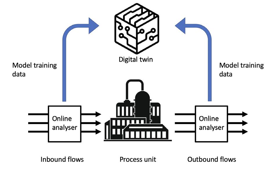
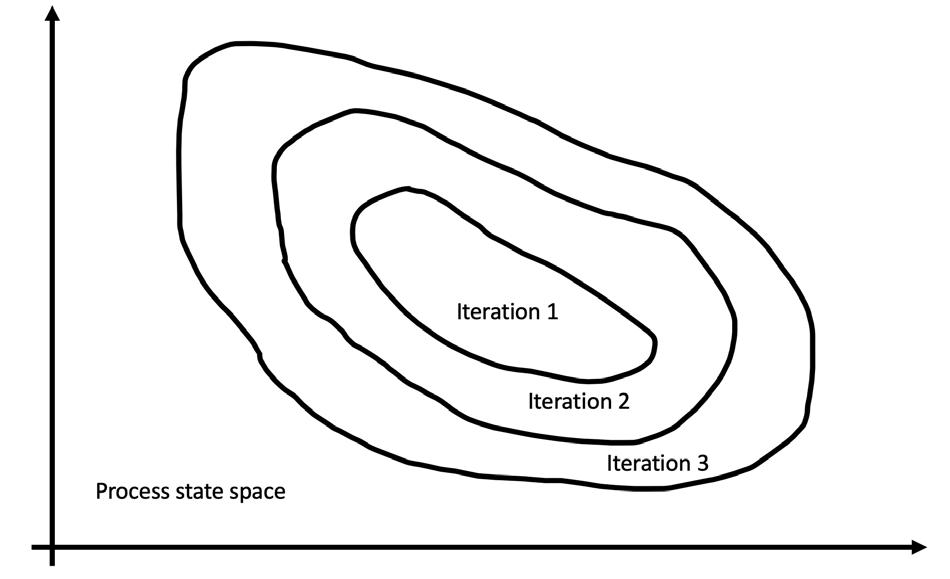
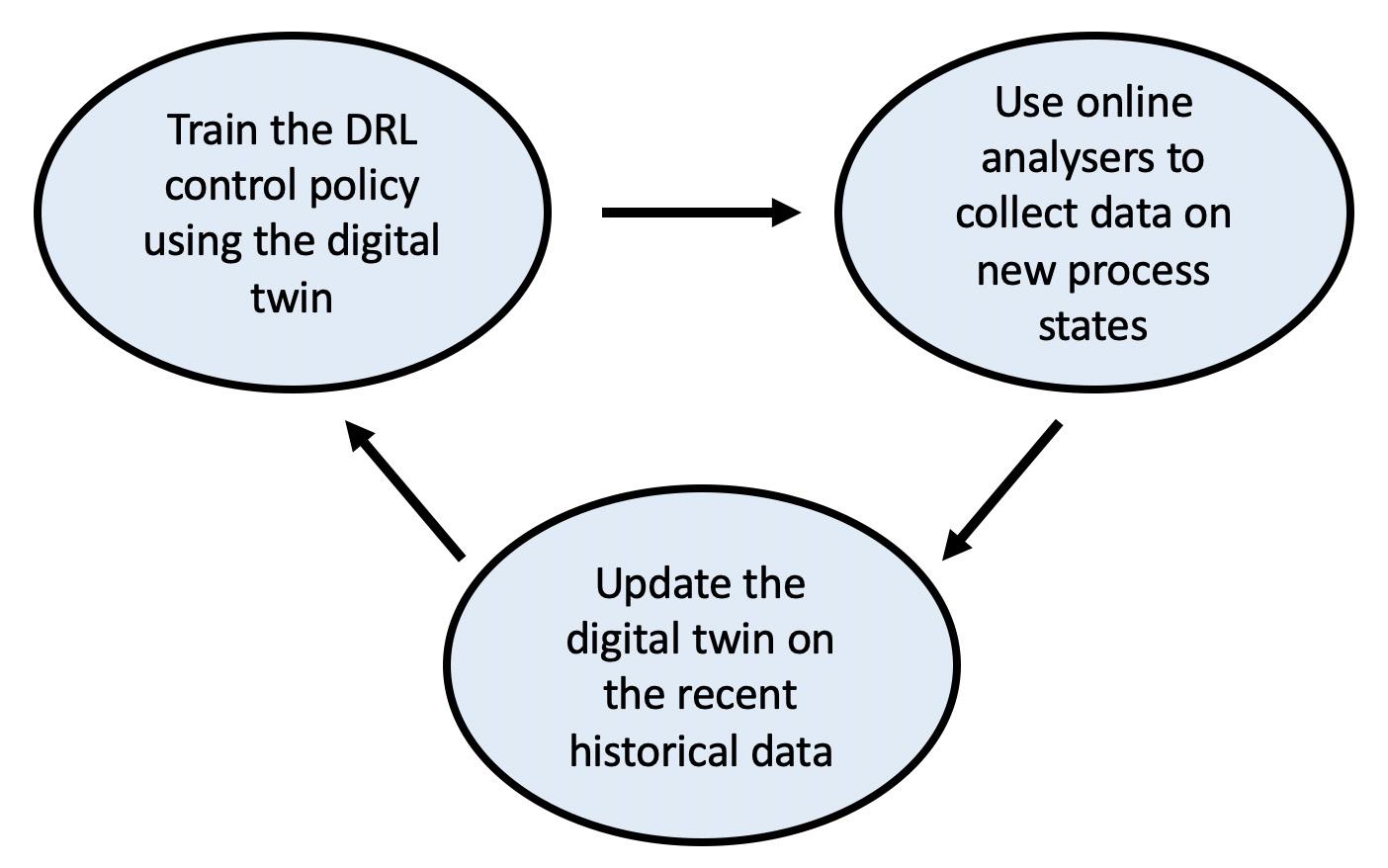
Conclusion Predictable behaviour and safety are the important factors in deciding on an APC solution. This article has shown that DRL technology allows for a scalable optimising control solution, without compromising the fidelity of the process modelling. For the processes modelled by the digital twins, based on ML/AI technology, safe deployment of DRL entails the gradual expansion of the range of permitted process states that the DRL controller can guide the process through. Online analysers are an important part of implementing this approach, as they capture the additional blocks of historical data used to update the digital twin with the process dynamics in the new states visited by the process, as depicted in Figure 3.
area of robotics, where the objective was training a robot without causing it mechanical damage. The fruits of this research are applicable to using DRL in process control. In evaluating the reward accrued by following the DRL control law, the reward collected from the states that are remote from the historically-visited ones is penalised. The successful and safe deployment of a DRL-based, real-time process optimisation solution will involve cyclically repeating the three steps, as depicted in Figure 1. In the first step, the current version of the DRL control law is applied to steer the live process. Under this updated control policy, over time the process will visit new states not visited under the previous versions of the controller, as shown in Figure 2. In the second step, online analysers are installed on the inbound and outbound flows of each of the units within the optimised technological chain to precisely capture the new aspects of the process dynamics. In the third step, the newly-captured historical process data is used to further update the digital twins of each of the optimised units. As the DRL controller takes the state of the process as an input and produces the appropriate process control signal as an output, a decision needs to be made with regards to which elements of the process data should be incorporated into formulation of the state for each process. In process control, the control signals are the MVs that are periodically applied to the controlled unit. For example, when dealing with a technological unit that gradually responds to a change in MVs, a relevant number of the MVs produced by the DRL in a number of the previous iterations may need to be incorporated into the state vector. This is analogous to considering a series of historic values of the MVs when calculating the next one in a traditional MPC multivariate control algorithm. The selection of the parameters constituting the DRL state will require the corresponding choice of the digital twin parameters. If the real process responds gradually to a change in MVs, the digital twin should allow an operator to take a series of historic values of the MV over a certain time horizon as a parameter, to allow for the training of the DRL in simulation.

We have assembled over 20 excellent oil industry strategists and technology experts for our upcoming meeting to tackle the unprecedented challenges facing the crude market and the refining world that have been caused by Russia's invasion of Ukraine and the growing calls for decarbonization. As shown in the agenda (https://opportunitycrudes.com/?topics=conf&subtopics=agenda ), the conference consists of five core sessions to look at changing crudes for sustainability.
5. Refining process and catalyst innovations, biofuel production, and Internet of Things (IoT) technologies for fuel transformations Our meetings are known for providing a stimulating atmosphere for exchanging ideas, reconnecting, networking, and socializing with your colleagues over meals and receptions as well as productive discussions in townhall meetings. This conference is coordinated with the Crude Oil Quality Association's ( www.coqa inc.org) Oct. 26 27 event which will focus on the challenges and opportunities in upstream and midstream businesses because of crude quality matters related to current shifts in global procurements and increas ing exports of US oil abroad. So, come to join us at this special Opportunity Crudes COQA summit!
3. Crude management to improve feed quality and to aid in refinery decarbonization
Register today to take advantage of pre conference discount by visiting: https://opportunitycrudes.com/registration22.php

Sponsored By:

Refining in Transition: from Vision to Execution amid Crude Disruptions

OPEN FOR REGISTRATION
Media Partners:


1. Outlooks and insights of shifting global oil supply and demand in uncertain times amid the energy transition 2. Crude selection and trading: favoring low-carbon-intensity crudes
Hosted By: Hydrocarbon Publishing Company Translating Knowledge into Profitability® Frazer, PA (US), 1 610 408 0117, info@hydrocarbonpublishing.com

Hydrocarbon Publishing Co. is inviting you to attend the 8 th Opportunity Crudes Conference, which will be held in person (in Houston, Texas, US) and virtually (via Zoom) during October 24 26. Please visit https://opportunitycrudes.com/ to learn more about this 2½ day meeting, which is centered on the theme:


4. Refiners' flexibility to process changing crudes and to meet product shortfalls

T he demand for stronger cybersecurity controls in the oil and gas industry soared in 2021. High-profile cyber incidents in the past five years, including the Colonial Pipeline incident, the 2020 ransomware attack at an unnamed US natural gas facility, and the devastating TRITON attack, all garnered significant media attention because of the real-world impacts that were felt by both the companies and their customers. Although cybersecurity has had an increased presence in the news cycle, it is not a new phenomenon. In 2012, Chinese hackers broke into the systems of one of the largest gas supervisory control and data acquisition (SCADA) system providers, and stole project files and source code. The industry’s reaction was muted, with the system vendor downplaying the incident. Heads were stuck in the sand, and over a decade was lost for most companies that desperately needed to address the issue. These systems are still widely deployed.
September 202269HYDROCARBON ENGINEERING
Jim Crowley, Industrial Defender, USA, outlines the importance of cybersecurity in the oil and gas industry, and provides a step-by-step guide to cultivating a more cyber-aware business.

1. Safety/security matrix Safety issue Cybersecurity issue Near safety misses Near security incident – i.e. malware detection Minor safety incidents Breach with no operational downtime Safety incidents that lead to downtime Cyber incident that requires remediation and leads to facility downtime Fatalities Fatalities
OT vs IT security
“You can’t manage what you can’t measure” is a common quote in management consulting circles, and it truly does apply in this context. Managing risk is what a successful cyber program is all about. A program will never be 100% risk-free, but by implementing a cyber standard and getting the organisation on board to reduce risk, a program can be truly effective over time.
n Vulnerability monitoring – proactively identify and mitigate vulnerabilities to minimise the window of opportunity for attackers.
September 2022 HYDROCARBON ENGINEERING 70
Once the foundational controls are in place, companies should start to work on more advanced program enhancements, such as the following: n Establish metrics on the program and measure them. Companies should ask themselves: how many critical unpatched systems do we have? How many devices are not communicating or need to be onboarded? Is someone reviewing baselines daily or weekly?
Playing catch up Step one: carry out an assessment Across social media, television and other outlets, there are an increasing number of advertisements promoting ways to protect systems from a cyber attack. Whilst it might be tempting to implement these readily-available tools quickly, it is best to undertake a cyber assessment to determine where the biggest risk lies, and where investments need to be made in order to plug the gaps. There are quite a few consulting companies that specialise in carrying out OT assessments, with different scope and price points. Deloitte, Accenture, ABS and Burns & McDonnell all have dedicated OT security teams for the oil and gas industry that can conduct a risk assessment and make recommendations on setting up a program.
Most OT cyber standards come from the same playbook, but choosing one such as the Center for Internet Security (CIS) Controls, NIST CSF (this may be a requirement for some firms in the near future) or IEC 62443 will help to successfully manage risk in an OT environment, and demonstrate results to senior management or the board.
Some technologies can be the same, such as firewalls that exist between plants and corporate networks, or anti-virus software that an original equipment manufacturer (OEM) has tested and recommended to run on human-machine interfaces (HMIs) and servers. However, other technologies with heavy footprint agents that block processes, such as managed detection response (MDR) tools, are disliked by OT engineers, as expert human operators need to remain in the loop with regards to any changes to real-time processes. Further complicating matters, IT usually has specialised tools and skillsets to manage the different disciplines. There might be a network engineer that has sophisticated IT network tools, a data centre specialist that has tools to manage corporate Linux and Windows servers, or a desktop specialist that has desktop tools. If a company has a security operations centre (SOC), it may have security information and event management (SIEM) and MDR tools to manage risk on IT assets.
Step four, five, six and beyond: focus on maturing the security program
n Develop policies and monitor users and passwords, and implement the recommended policies stipulated by company’s chosen standard. For example, passwords should be of sufficient strength and aged out periodically.
All of the common cybersecurity standards will recommend deploying foundational security controls on OT assets as part of their program. In fact, the CIS – a non-profit cyber standards body – has published studies that demonstrate that by implementing just the top five controls to systems, the risk of breach can be reduced by 85%.
Step three: deploy foundational OT security controls
n Deploy an OT network intrusion detection system (IDS) to monitor outbound communications and carry out Table
n Configuration change management – monitor for any configuration changes in hardware and software.
Step two: choose a standard
The top five recommended controls are: n Inventory of hardware assets – create and maintain an accurate inventory of all hardware devices in OT environments. n Inventory of software assets – create and maintain an accurate software inventory for the end points in OT environments.
As anyone working at an industrial facility knows, real-time systems are different to the systems found in the data centre, or applications that are cloud-based. The real-time nature and network protocols of SCADA-based technologies create challenges for deploying standard IT tools and technologies in oil and gas infrastructure.
Oftentimes, OT faces all of the same challenges as IT when it comes to managing industrial networks, but not the specialists or tools to run them. Operators should be looking for strategies and tools that are OT-focused in order to manage the unique requirements of their control system infrastructure.
n Event log management – create, maintain and monitor OT security event logs to help detect and respond to a cyber attack.
September 2022HYDROCARBON ENGINEERING 71 For all your critical infrastructure needs, o shore and onshore. O shore automation control systems face cyber risks that may not have been identified or addressed. Enhanced risk assessments and mitigation, field verification, training and continuous detection improves system preparedness to meet threats and challenges head-on. Learn more at 1898andco.com/HydrocarbonEngineering22.


n If an organisation is large enough, companies could consider building a security operations team to review alerts 24 hr/d, or outsource to a group that has OT security operations experience.
Conclusion Reducing a company’s cyber risk is not a one-time event or CAPEX. Instead, it is a journey that requires constant attention, just as with safety considerations. Whilst it is a large challenge, it can be managed just as any other risk to a business. When broken down into achievable goals, companies can avoid downtime and substantially reduce the risk of unpleasant surprises.
A company’s cybersecurity journey can commence simply by adding the topic of cyber safety into the conversation during internal meetings, in order to begin creating a culture of cybersecurity awareness, just as the industry did with safety.
n For very large organisations, there are also advanced machine learning technologies – as well as threat intel feeds – that can help provide situational awareness on top of the foundational controls to augment standards-based programs.
HSE best practices can be closely aligned to a cyber program. An OT cyber incident is not just a business issue. Rather, it is a safety issue, as recently demonstrated by hacks into OT systems in several different industries.
Cultivating executive support
September 2022 HYDROCARBON ENGINEERING 72 deep packet inspection (DPI) on traffic. Having an IDS will provide an additional layer of visibility into what is happening on a network. Understanding what outbound connections systems might have – or start to have – as well as examining network activity for suspicious traffic, could be an early indicator of compromise.
The connection between safety mitigation and cybersecurity can help position a cyber program with senior management and the board. For oil and gas companies, an important concept to consider is that the safety of employees and the environment depends upon the strength of that organisation’s cybersecurity. Much of the success that the oil and gas sector has had in mitigating the risks of working with a combustible element in a dangerous environment has been by implementing stringent health, safety and environment (HSE) procedures that track incidents and near misses, not just injuries and fatalities.
Framing the discussion as cyber safety and bringing the discipline of a safety program to the table as a means to mitigate risk has been an effective way for executives to understand the risks and the investments that are required to ensure the safety and operational integrity of an asset base.
Page Number | Advertiser 71 | 1898 & Co., part of Burns & McDonnell 35 | ABC 63 | ADIPEC 59 | Advanced Refining Technologies LLC (ART) 44 | Albemarle 31 | API Storage Tank Conference & Expo OFC & 25 | Athlon, a Halliburton Service 09 | Axens 07 | BASF 53 | Chevron Lummus Global (CLG) 47 | Crystaphase 04 | Eurotecnica 35 | General Atomics Electromagnetics 55 | Heat Transfer Research, Inc. 17 | Hitard Engineering 27 | Koch Engineered Solutions 37 | MERYT Catalysts & Innovation 68 | Opportunity Crudes Conference 21 | Optimized Gas Treating, Inc. 50, 56, 61, IBC | Palladian Publications Ltd 49 | Paratherm 43 | Sabin Metal Corp. 13 | Saint-Gobain IFC | Selective Adsorption Associates, Inc. 02 | Topsoe 19 | VEGA 67 | Watlow 41 | W. R. Grace & Co. OBC | Zeeco Inc. AD INDEX