World news 07 Connecting the oilfield of the future
Ross Mahler, Moxa.
12 FPSO reliability and filtration
Pete McGuigan, Parker Filtration Group.
Abaco delivers the power to drill faster, deeper and farther by creating advanced engineering designs and technologies that enhance power section performance and reliability. Fieldproven innovations like OPTIFIT® stators and high temperature 350 - 400˚F elastomers have successfully powered thousands of runs worldwide. Abaco’s specialised power sections, in diameters ranging from 1-11/16 in. to 11-3/4 in., deliver the durability and optimised performance the oil and gas industry demands in challenging, corrosive, high-temperature, hightorque, and high-wear conditions. https://abacodrilling.com/
20 Flow remediation in subsea environments
Leonard Hamill, Pipetech.
The pressure of protection
Julian Yeo, United Electric Controls.
Beyond NPEs
Dr. Silke Hoppe and Dr. Cornell Stanciu, Sasol Chemicals.
Developing a retrievable remote open barrier plug
Geir Melhus, TCO.
Embracing remoteness
Mike Brown, Blackline Safety.
Why is OPTIFIT the optimum choice for drilling in 350°F - 400°F temperatures?
OPTIFIT
It ’s been done thousands of times. More than 10,000 successful OPTIFIT runs in three years. We employ leading-edge technologies to overcome harsh, high temperature drilling conditions you face. Engineering innovations like patented deviated profiles that reduce friction on the lower end. Proprietary elastomer formulas like HPW (up to 350°F) and HPT (up to 400°F) address elevated downhole temperatures. These power section advancements deliver higher power output, increased bond strength, maximized durability and improved fluid resistance.
Explore Abacodrilling.com and learn how OPTIFIT Power Section Stators can handle the heat.
LEADING POWER SECTION TECHNOLOGY
Comment
March/April 2025
Elizabeth Corner, Senior Editor elizabeth.corner@oilfieldtechnology.com
At the end of March, global oilfield services giant SLB secured a significant drilling contract from Australian independent Woodside Energy for the ultra-deepwater Trion project offshore Mexico.
Located in around 2500 m of water in the Perdido Foldbelt, approximately 180 km off the Mexican coastline and 30 km south of the US maritime boundary, the US$7.2 billion Trion development marks a major upstream investment. Under the contract, SLB will manage the delivery of 18 ultradeepwater wells, leveraging an integrated services model and AI-driven drilling technologies to enhance efficiency and well performance.
Petróleos Mexicanos (Pemex) still dominates the upstream market in Mexico, especially offshore, but its financial struggles and production decline have created space for more private investment and partnerships, albeit cautiously. Mexico’s landmark 2013 energy reforms opened the upstream sector to private and foreign investment, which led to some promising offshore discoveries. However, under President Andrés Manuel López Obrador (AMLO), new bidding rounds were frozen, and the policy stance doggedly favoured Pemex. This has slowed momentum and created investor uncertainty.
Mexico’s offshore Gulf of Mexico acreage is geologically promising, on par with the US side, but investment appetite hinges heavily on regulatory clarity and fiscal terms. Elections in summer 2024 made Claudia Sheinbaum Pardo the new President. During polling she expressed her determination to continue AMLO’s policies, particularly with regards to private investment in the country’s energy sector. Opposition candidates had argued for greater involvement of private firms in the energy sector and downsizing Pemex refining capacity.
Pemex has registered net profits in only three of the past 14 years (2012, 2022 and 2023) and is overwhelmed by debt and lower-than-projected crude oil production. According to the Center on Global Energy Policy at Columbia, crude oil production is an “area of concern. While the [AMLO] administration can be credited with slowing down the pace of decline registered in previous years, production increases (excluding condensates) have not been achieved. Between 2018 and 2023, crude oil production shrank by 0.22 million bpd, or 12%.”1
The task of turning Pemex into a profitable organisation that can stand on its own relies on a delicate balance of operational efficiency, strategic investment, fiscal discipline, and supportive policy reform, as well as meaningful collaboration with the private sector to bring in capital, technology, and expertise.
The resilience of offshore activity, despite the political challenges, is encouraging. There are some notable upstream offshore developments in Mexico that reflect ongoing activity and progress, including Talos Energy’s Zama field (a world-class shallow-water discovery), although it has been caught in a tug-of-war with Pemex over operatorship. Companies like Eni and Wintershall Dea have continued drilling and appraising offshore blocks, showing long-term commitment to the region. Mexico’s offshore upstream sector still holds promise, especially where earlier bidding round awards are being matured, even in a challenging policy climate.
I hope you enjoy this issue of Oilfield Technology, which covers wellsite monitoring, drilling performance, autonomous oilfields, FPSOs, subsea production challenges, and well pump operations. 1. https://www.energypolicy.columbia.edu/understanding-pemexs-post-election-challenges-through-six-charts/
Contact us
Editorial
Managing Editor: James Little james.little@oilfieldtechnology.com
Editorial Assistant: Alfred Hamer alfred.hamer@oilfieldtechnology.com
Design
Production Designer: Iona MacLeod iona.macleod@oilfieldtechnology.com
Production Manager: Kyla Waller kyla.waller@oilfieldtechnology.com
Sales
Sales Director: Rod Hardy rod.hardy@oilfieldtechnology.com
Sales Manager: Chris Lethbridge chris.lethbridge@oilfieldtechnology.com
Sales Executive: Daniel Farr daniel.farr@oilfieldtechnology.com
Events
Head of Events: Louise Cameron louise.cameron@oilfieldtechnology.com
Digital Events Coordinator: Merili Jurivete merili.jurivete@oilfieldtechnology.com
Junior Video Assistant: Amélie Meury-Cashman amelie.meury-cashman@oilfieldtechnology.com
Website
Digital Content Coordinator: Kristian Ilasko kristian.ilasko@oilfieldtechnology.com
Digital Administrator: Nicole Harman-Smith nicole.harman-smith@oilfieldtechnology.com
Marketing
Administration Manager: Laura White laura.white@oilfieldtechnology.com
Reprints: reprints@oilfieldtechnology.com
Palladian Publications Ltd, 15 South Street, Farnham, Surrey GU9 7QU, UK Tel: +44 (0) 1252 718 999 Website: www.oilfieldtechnology.com
Still pioneers.
World news
Equinor brings Johan Castberg oilfield onstream
Equinor has announced the Johan Castberg oilfield in the Barents Sea has come onstream. The field will be producing for 30 years. At peak, Johan Castberg can produce 220 000 bpd of oil, and recoverable volumes are estimated at between 450 and 650 million barrels.
“This is a red-letter day. The Johan Castberg field will contribute crucial energy, value creation, ripple effects and jobs for at least 30 years to come. We expect that this major field development with a price tag of NOK 86 billion (2024) will be repaid in less than two years,” says Geir Tungesvik, Equinor’s Executive Vice President for Projects, Drilling and Procurement. 12 of the 30 total wells are ready for production, and this is sufficient to bring the field up to expected plateau production in 2Q25.
“Johan Castberg opens a new region for oil recovery and will create more opportunities in the Barents Sea. We’ve already made new discoveries in the area and will keep exploring together with our partners. We’ve identified options to add 250-550 million new recoverable barrels that can be developed and produced over Johan Castberg,” says Kjetil Hove, Equinor’s executive vice president for Exploration & Production Norway.
The Norwegian supplier industry has accounted for more than 70% of deliveries to the project during the development phase. In operation, this will increase to more than 95%, with a Northern Norwegian share of more than 40%. One of three employees on board the FPSO lives in Northern Norway. 84% of the revenue from the field will be transferred to the Norwegian state through tax and the state’s direct participating interest. The field’s supply base and helicopter base are in Hammerfest and will be operated from Equinor’s office in Harstad. A total of 30 wells will be drilled on the Johan Castberg field, and drilling operations are expected to continue towards late 2026, which will yield significant activity in Hammerfest.
“Johan Castberg has been a massive and challenging project, and I want to extend my very sincere thanks to everyone who contributed on the road leading to first oil and operation, both our partners Vår Energi and Petoro, our suppliers and our own employees. 79 million hours of work have been recorded in the project, and the HSE results are very good. Now the field will produce for 30 years and generate substantial values,” Tungesvik says.
DNO announces North Sea oil and gas discovery
DNO ASA, the Norwegian oil and gas operator, has announced an important oil and gas discovery in Northern North Sea license PL1182 S in which the company holds a 40% operated interest. The discovery was made in Paleocene injectite sandstones of excellent reservoir quality with preliminary estimates of gross recoverable resources in the range of 39 - 75 million boe, with a mean of 55 million boe.
The Kjøttkake exploration well encountered a 41 m oil column and a 9 m gas column. A sidetrack drilled horizontally 1350 m westwards along the reservoir in the Sotra Formation confirmed the presence of the oil column throughout the discovery
“We are on a hot streak in Norway,” said Executive Chairman Bijan Mossavar-Rahmani. “Our latest and most exciting discovery this year, Kjøttkake, is close to existing infrastructure in the Troll-Gjøa area, and we will be relentless in pursuing its commercialisation.”
Located 27 km northwest of the Troll C platform and 44 km southwest of the Gjøa platform, Kjøttkake is DNO’s tenth discovery since 2021 in the Troll-Gjøa exploration and development hotspot, following Røver Nord, Kveikje, Ofelia, Røver Sør, Heisenberg, Carmen, Kyrre, Cuvette and Ringand. The Company has also racked up discoveries in other parts of the Norwegian Continental Shelf, including Norma (2023) and Othello (2024), both play-opening finds and both operated by DNO. Partners in license PL1182 S include Aker BP ASA (30%), Concedo AS (15%) and Japex Norge AS (15%). The wells were drilled using the Deepsea Yantai rig.
Following its exploration success, the company has stepped up purchases of producing assets to balance its Norwegian portfolio and help fund coming developments. In early March, DNO announced the transformative acquisition of Sval Energi Group AS, which will increase North Sea 2P reserves from 48 million boe to 189 million boe post-closing and 2C resources from 144 million boe to 246 million boe (pro forma figures as of year end 2024).
March/April
2025
Nigeria
Aquaterra Energy has secured a multimillion-dollar well intervention contract with Intrepid Energy in Nigeria.
Norway
Island Drilling Company AS has been awarded a three year contract for well plugging on Equinor-operated fields on the Norwegian continental shelf.
UK
Ithaca Energy has announced its acquisition of JAPEX UK E&P Ltd, building interest in the Seagull field.
Iraq
bp has received final government ratification for its contract to invest in the redevelopment of several giant oilfields in Kirkuk, in the north of Iraq.
Brazil
TechnipFMC has been awarded a major contract by Shell for its Gato do Mato greenfield development offshore Brazil.
Thailand
Horizon Oil has announced the acquisition of 7.5% interest in Sinphuhorm and 60% of Nam Phong producing gas fields, onshore Thailand.
Libya
Libya’s National Oil Corporation has resumed oil production at the Mabruk oilfield after a 10 year hiatus. The field is currently producing 5000 bpd, with an expected increase to 25 000 bpd by July.
Guyana
The ABS-classed Liza Unity has become the first FPSO in the world to receive the SUSTAIN-2 notation from ABS.
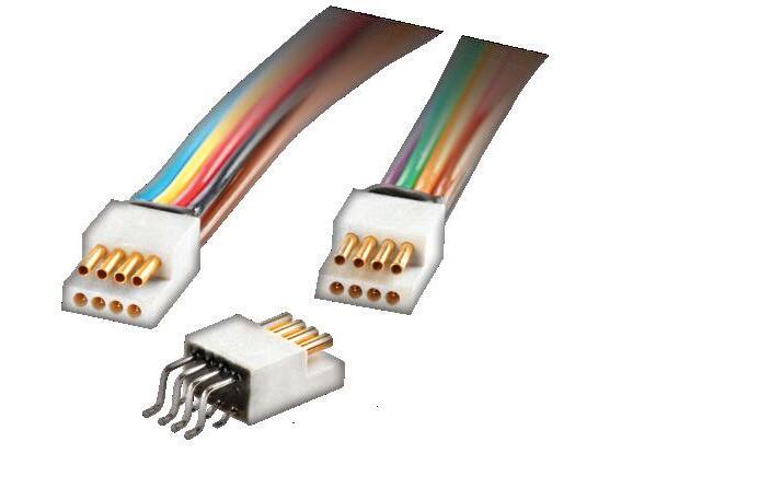
Connecting the oilfield of the future
Ross Mahler, Moxa, discusses the technologies providing upstream oil and gas operators with reliable visibility and live connectivity to their artificial lift assets, increasing equipment uptime and hydrocarbon production while reducing the need for manual intervention.
The upstream oil and gas sector, characterised by harsh remote environments and reliance on ageing infrastructure, often lags behind other industries in embracing the transformative power of digitalisation. This hesitancy to retrofit stems from a complex interplay of factors, including a persistent tried-and-true run-to-failure mentality, the cyclical nature of oil prices – which impact funding for capital improvement projects – and the perceived complexity of integrating new technologies with legacy systems.
However, with the rise of the industrial internet of things (IIoT) and these factors in mind, the industry is at a crossroads. Mounting pressures to optimise production, reduce operational costs, minimise environmental impact, and enhance worker safety are forcing upstream operators to rethink traditional maintenance and control approaches, and to explore implementing the oilfield of the future.
Among the emerging innovators, Boomerang is leading the way with cutting-edge monitoring, control, and data acquisition solutions tailored to the upstream oil sector. Founded in 2012, Boomerang is located in Houston, Texas in the heart of the oil and gas industry. By providing
the tailored software for accessing high-availability sensor data and deploying it on hardware supplied by Moxa, a provider of industrial communication and networking technologies, this platform is providing operators with insights to optimise oil field operations.
Equipping wells with SCADA capabilities
For decades, the upstream oil and gas industry operated in a data-scarce manner, where manual data collection, on-site inspections, and reactive maintenance strategies were standard. This approach resulted in inefficiencies, unexpected downtime, increased costs, and compromised safety in the worst cases because sites are often distributed over large areas.
There is a large installed base of legacy equipment still in use today. With an estimated one million overland oil and gas wells in the US, a staggering 60% of them still lack any form of automated and real-time telemetry, and this delay in manually gathering critical operational data can postpone decision-making, increase risk, and compromise optimisation opportunities.
Small producers are often more open to introducing new technologies, while largescale rig operators have more rigorous procedures for adopting upgrades. However, teams of all sizes are being tasked to do more with less. Like many industrial sectors, upstream oil and gas is struggling with an ongoing shortage of skilled personnel, which is increasing the need for automated solutions to reduce manual workloads, inspections, and equipment adjustments.
As a result, industry is striving for autonomous oilfields. For these geographically distributed operations, IIoT-based supervisory control and data acquisition (SCADA) platforms are helping achieve this vision by connecting previously isolated assets to digital networks, enabling real-time data collection, analysis, and action based on vast amounts of operational information. This in turn is empowering rig operators to make informed decisions, optimise production, reduce downtime, and improve safety.
Purpose-built, yet industry agnostic
Capitalising on the vast potential of IIoT for upstream oil and gas, Boomerang is an out-of-the-box control, data acquisition, and analytics solution that drives efficient field operations, and helps users access their valuable data and put it to work. Boomerang also provides holistic complex closed-loop control capabilities for automated well management, including anomaly identification and correction.
The platform is tailored to address the specific challenges of this sector, yet it is versatile enough for deployment in other industries. The primary goals of Boomerang are to quickly consolidate real-time data from remote units across an enterprise, and to provide a centrally connected hub with intuitive dashboards for monitoring and control of all forms of artificial lift. These include gas lift, electric submersible pump, jet pump, plunger lift, and sucker rod pump.
Unlike traditional SCADA systems – which are often far more complex and expensive to deploy – Boomerang SCADA prioritises ease of use, affordability, and seamless integration with existing infrastructure, empowering companies of all sizes to make data-driven decisions. The platform’s low-code setup enables even users with limited IT expertise to easily configure and customise the visual interfaces to meet unique monitoring and control preferences, reducing barriers to adoption.
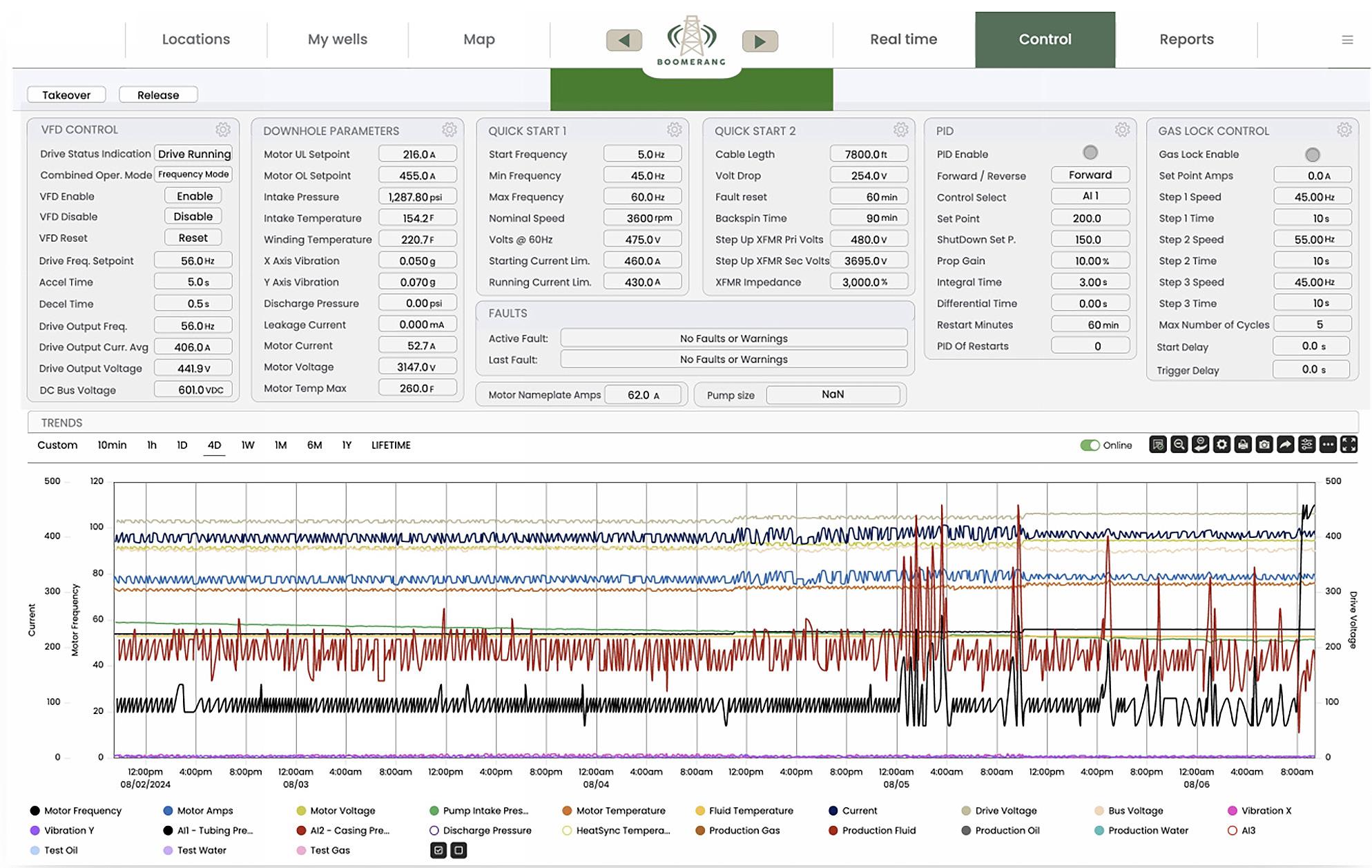
At its core, Boomerang encompasses a suite of userfriendly yet powerful tools, such as real-time dashboards, that provide operators with an at-a-glance equipment view, highlighting key parameters like production rate, pressure, temperature, and alarm status (Figure 1). This rapid access to critical information promotes proactive decision-making and rapid response to potential issues, minimising downtime and maximising production efficiency.
Figure 1. Boomerang’s easy-to-read dashboards provide personnel with an at-a-glance equipment view, highlighting key performance parameters.
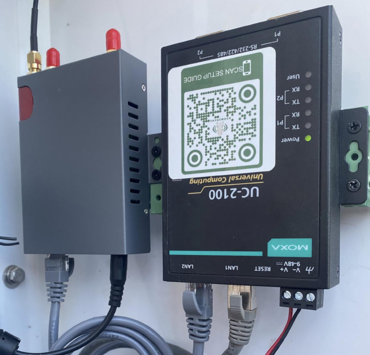
Figure 2. The Boomerang application is built on Moxa’s durable UC-2100 industrial IIoT gateway, providing reliable and cybersecure oilfield connectivity regardless of the environmental conditions.
Furthermore, historical data analysis tools enable users to investigate past performance, identify trends, and mitigate problems before they escalate into costly shutdowns. By understanding historical well behaviour, operators can fine-tune production parameters, optimise maintenance schedules, and extend the lifespan of their equipment.
Additionally, automated reporting capabilities simplify regulatory compliance and performance tracking. The system is equipped out-of-the-box to generate reports on production, downtime, alarms, and other key metrics, freeing up valuable time for operators to focus on optimising operations, instead of manually building reports.
Effective alarm management is critical in every industrial setting, but especially for equipment in the remote and hazardous environments customary to upstream oil and gas. Therefore, Boomerang’s alarm management system is specially crafted to draw attention to abnormal conditions, prompting operators to take swift action. This proactive approach minimises downtime, reduces the risk of costly equipment failures, and enhances worker safety.
Addressing connectivity challenges with Moxa
While establishing the right set of user-friendly monitoring and control tools is essential, the success of an IIoT implementation also depends on reliable and cybersecure communications infrastructure. Recognising the critical importance of stable oilfield connectivity, Boomerang partnered with Moxa – a global leader in industrial networking and communications solutions – to provide ruggedised, industrial-grade hardware for uninterrupted connectivity. A proven track record and demonstrated supply chain competencies were key to this decision. Moxa’s UC-2100, 3100, and 8100 series of industrial IIoT gateways comprise the backbone for Boomerang deployments, ensuring robust data transmission even in the most challenging environments (Figure 2).
These gateways are made to withstand extreme temperatures – ranging from -40°F found in North Dakota winters to 120°F experienced in Texas summers – and also vibration and electromagnetic interference present at these locations, while maintaining steady connectivity for continuous data feeds from the well site to the control room.
Many remote well sites lack access to traditional wired network infrastructure, so the cellular capabilities of these gateways provide a cybersecure and reliable wireless connectivity
solution. These IIoT gateways include a cybersecure microservices cloud environment on which custom applications, such as Boomerang, are built. This enables remote monitoring and control from any authenticated device with a web browser, unlocking valuable data and enhancing control (Figure 3).
Each gateway has the capability to manage wells at the pad level, with complete scalability in mind. A typical Boomerang install base extends to about 3000 IIoT gateway devices, brokering connectivity among 3500 – 4000 wells in total.
The collaboration between Boomerang and Moxa extends beyond the hardware and software. Boomerang developed a custom communications protocol based on industry-standard MQTT and optimised for the unique constraints of oilfield operations. This protocol prioritises high-frequency, ‘on-change’ data transmissions, enabling reliable communication even over bandwidth-constrained connections, which are common in remote oilfield locations.
Efficiency, safety, and data-driven success
The combined expertise of Boomerang and Moxa is accelerating upstream oil and gas digital transformation. End-users who have installed the joint solution report significant improvements across various key performance indicators, demonstrating the tangible benefits of this strategic partnership.
Boomerang has converted every one of its pilot projects to permanent deployments, a testament to the platform’s effectiveness and user appeal. Commissioning is overwhelmingly simple, exemplified by one end-user who deployed more than 20 devices per day, connecting multiple lift types and wells on each device.
The most noticeable end-user benefits are increased production efficiency, decreased downtime, and lowered operational costs. These efficiency gains are a result of platformprovided real-time insights into well performance, which enable proactive maintenance through automated alerts. Increased uptime translates directly to higher production rates and increased revenue, and the reduced need for manual intervention results in improved safety.
Preparing the oil and gas sector for the future
The upstream oil and gas industry is undergoing a period of profound change. The old ways of operating are not viable in the new labour market, and the need to optimise production, enhance worker safety, and improve overall efficiency is driving a rapid shift towards digitalisation. By automating tasks, enabling remote monitoring, and optimising well management strategies, the Boomerang software solution built on Moxa’s reliable hardware is streamlining workflows and operational efficiencies for upstream operators.
Boomerang is committed to constant innovation, a continued focus on developing advanced closed-loop control schemes, expansion into international markets, and delivering exceptional end-user value. In an industry where operating costs are constantly under scrutiny, the ability to improve efficiency and minimise expenses is critical.
Complex challenges often require cooperative solutions, and partnerships like the Moxa-Boomerang collaboration are critical for successful IIoT industrial implementations. The Boomerang solution demonstrates the power of leveraging the complementary strengths of different entities to accelerate innovation and deliver digital transformation.
Figure 3. The Boomerang solution enables remote cybersecure connectivity to wellsite sensor data from any authenticated device with a web browser.
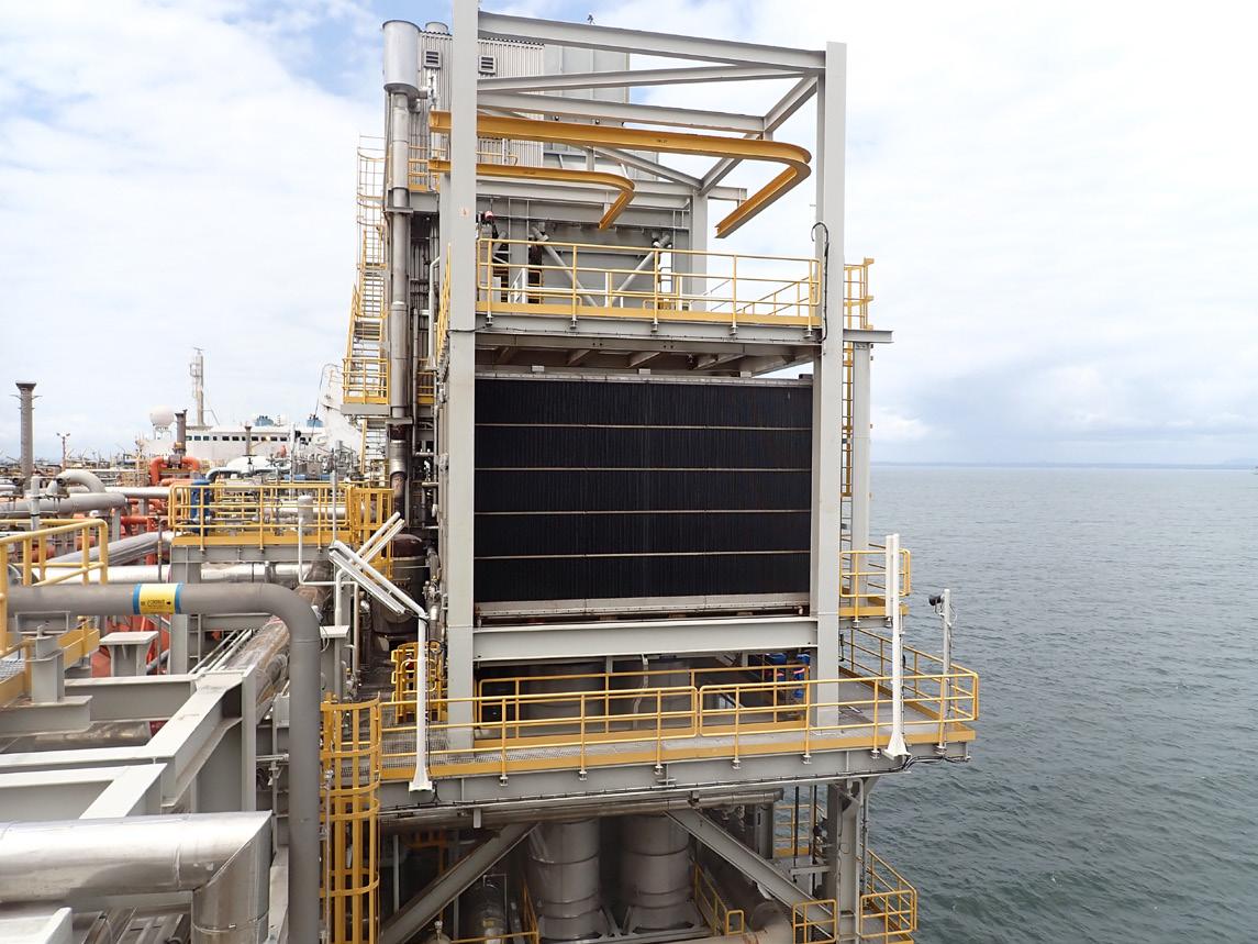
FPSO reliability and filtration
Pete McGuigan, Global LNG Market Manager, Filtration & Energy Solutions Division, Parker Filtration Group, explores the critical factors in selecting air intake filtration equipment for FPSO applications.
While floating production storage and offloading (FPSO) deployment is rising to become a major element of the offshore oil and gas production asset base there is no less emphasis on the must-run nature of key equipment onboard. For the gas turbines that provide electrical power as well as key equipment mechanical drive, the critical denominator of performance and reliability is effective combustion air intake filtration.
Oil and gas exploration and production increasingly rely on FPSO vessels that allow hydrocarbon production in remote, deep-water areas that would be uneconomic to develop using conventional tension leg or fixed pile structures. The changing economics of oil and gas production has led to sharp growth in
the deployment of FPSO vessels. Today, they tend to dominate the space in place of more permanent platforms and structures that have previously been the preferred choice. A key benefit of FPSO technology is its flexibility, allowing expensive production assets to be relatively easily relocated in response to changing reserve economics. It is also typically easier to obtain permitting and licensing for structures that are not permanent. As a result, today FPSOs are commonly found working oil and gas reserves in regions such as the east of Brazil and offshore of West Africa.
Typically located far offshore, like their fixed forebears these must-run applications demand the highest reliability to keep production running at full capacity no matter how harsh the environment.
One of the most important pieces of production equipment for FPSO vessels are the gas turbines which provide electrical power as well as mechanical drive for various critical processes. Like any gas turbine, efficiency, performance, and operational longevity are all directly affected by contamination and potential erosion or corrosion of turbine internals. However, even though FPSOs
are slightly less challenged from a filtration perspective than on older generations of fixed platforms – they typically flare less for example –the marine environment hasn’t changed and is particularly unforgiving when considering precision equipment like an advanced gas turbine. A critical consideration then is to prevent corrosive materials and other contaminants from entering the machine at all and that places huge emphasis on effective filtration of the intake air.
Clean air and the challenge of the marine environment
Operating gas turbines consume huge volumes of air, making airborne contaminants a significant issue. Any materials entering the turbine can adhere to the blades of the machine where even a modest coating can have a substantial negative impact on aerodynamic efficiency. Any loss of efficiency has a cost implication but for demanding FPSO applications this can have much more serious consequences. One of the responses to turbine contamination is to execute an offline wash cycle. While this can restore some of the lost performance associated with contamination it also necessitates shutting down the turbine with a potential loss of production that could be worth millions of dollars. Even more significant is the threat of erosion or corrosion of the turbine internals. Accelerated wear can be catastrophic. It not only affects the compressor section as contaminants can be ingested deep within the machine and can therefore also affect components in the hot gas path such as combustors, bearings and the turbine section. Repairing worn components can be a lengthy and costly procedure, especially if, as in the case of an FPSO, the asset is typically located far out to sea. As with offline washes, turbine downtime also likely represents an extremely costly loss of production capability.
While the challenges of air intake filtration are broadly understood, FPSO installations face additional challenges associated with the harsh offshore environment such as bad weather and water coming from sources like rain, mist, fog and sea spray. They must also manage constraints that do not apply to nearly the same degree when considering their terrestrial equivalents. Principally this is a lack of space on board a marine production vessel. Consequently, not only are turbine islands for these applications designed to be as compact as possible, but this also applies to all the related ancillaries, including the air intake filtration system.
Compact and fast is key
Given the extreme limitations of available space onboard FPSOs, gas turbine and compressor package OEMs have dedicated considerable resources to making high-performance systems that still deliver appropriate air quality for the turbine intake, but without the footprint commonly associated with terrestrial GT intake filtration. The Baker Hughes SeaSmart offshore packageTM solution is one such advance.
Achieving this performance within a reduced and compact footprint has led to the development of filtration systems which are very high velocity (compact) but have also relied on technical breakthroughs to ensure that the high velocities do not result in excessive pressure differentials across the required filtration components. To do so would impart significant performance losses. Parker, for example, offers several product ranges that support this compact high-velocity high-performance requirement.
Handling salt
One of the most important contaminants facing gas turbine operations offshore is airborne salt. Salt absorbs moisture readily and can move easily from solid to liquid form with changes in ambient relative humidity. A filtration system therefore needs to efficiently defend the turbine from both liquid and solid phase contaminants. When salt is
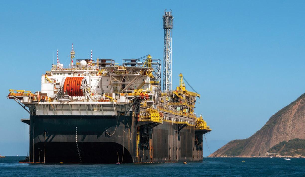
Figure 1. FPSO vessel temporarily moored close to Rio de Janeiro.
Figure 2. Parker designed PGT25+G4 combustion air intake system onboard a floating production vessel.
Figure 3. Typical Parker FPSO compact/high velocity GT air intake system configuration.
wet, it easily sticks to turbine blades and attracts other contaminants, quickly affecting the aerodynamic performance of the turbine. Unlike contaminants that cause fouling, one of the major problems with salt, however, is that the corrosion it causes is often not perceived in monitored turbine performance data until something physically breaks. Not only is salt highly corrosive but it is also technically very challenging to remove given it can change phase and then also combine with other contaminants like airborne particulate to create sticky mud-like substances that can clog filter media and impact the performance of other important GT air intake system components. In choosing air filtration equipment, the ability to prevent salt ingress without inducing high differential pressures is therefore critical and this starts by preventing water from entering the depths of the filterhouse.
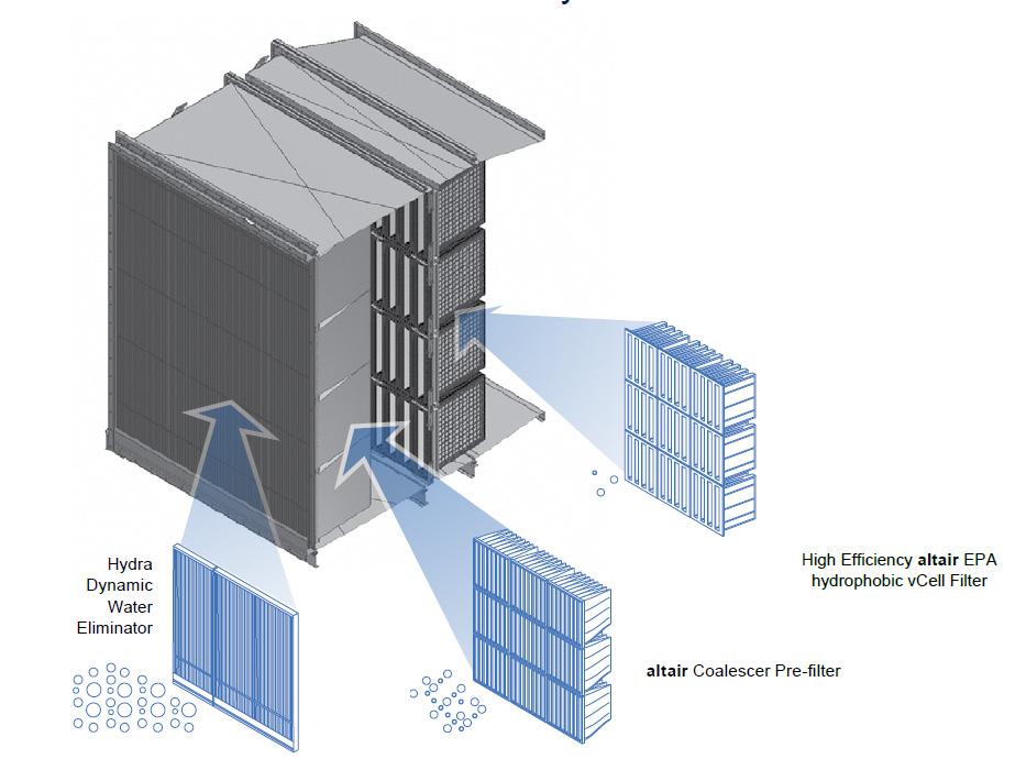
Salt can be difficult to handle because of its hygroscopic nature, meaning it has an affinity for water. Marine vessels, by their very nature, will always be exposed to a great deal of salt laden sea spray. To handle this salt effectively, a filtration solution needs to allow for input concentration, aerosol size distribution and aerosol physical state, whether droplet or particle. The right solution must also consider the impacts of increased pressure drop introduced by adding multiple filtration stages with salt protection. In order to stop salt getting downstream to the GT on an FPSO production vessel, designs have evolved so that the use of final stage hydrophobic EPA-rated filtration is today considered essential.
Beyond the design of the core equipment, other key performance factors include the build quality and the effectiveness of edge sealing. Any air that succeeds in bypassing the filtration system arrives at the turbine intake plenum complete with all its contaminants and effectively preventing any bypass is therefore critical. Dimensional stability, quality control in manufacturing, correct materials choices
and, in the long term, addressing factors like frame corrosion all have a major role in protecting marine gas turbines.
Underpinning performance
Nonetheless, the performance of this and other filtration system elements is underpinned by stringent testing and ongoing R&D investment. This is the only possible approach to revealing which air intake filtration systems are effective in real-world applications. In the case of the FPSO and their gas turbines, performance cannot be compromised. A series of tests and benchmarks have been established to understand saltwater removal performance that allows evaluation over multiple cycles and extended periods. Uniquely within the filtration industry, Parker Hannifin has established standards which have subsequently been adopted by many GT OEMs. Baker Hughes general specification SMO9981635 for offshore and coastal installations, as an example, details and references the Parker established MMBL reference salt aerosol to be used for system salt removal efficiency calculations. Parker’s extensive product development teams globally continue to illuminate filtration performance as it relates to saltladen water along with many other critical characteristics such as dust holding ability, pressure loss, fog and mist testing, heat ageing evaluation, acoustic testing and many others.
GT reliability for power production and mechanical drive are critical for FPSO applications and depend on effective gas turbine air intake filtration. Operational longevity and asset availability are essential characteristics for the core power production island in the face of dust and debris, hydrocarbons, salt water and harsh weather conditions that can all hurt turbine performance. When selecting air intake filtration equipment for FPSO applications, critical factors are the high velocity and compact footprint, performance of salt and contaminant removal, longevity, the package design and build quality, and for must-run applications, the GT air intake system OEM pedigree too.
Pete Cariveau and Jonathan Thiele, Abaco Drilling Technologies, USA, outline a project to address the thermal and mechanical challenges in downhole mud motor power sections.
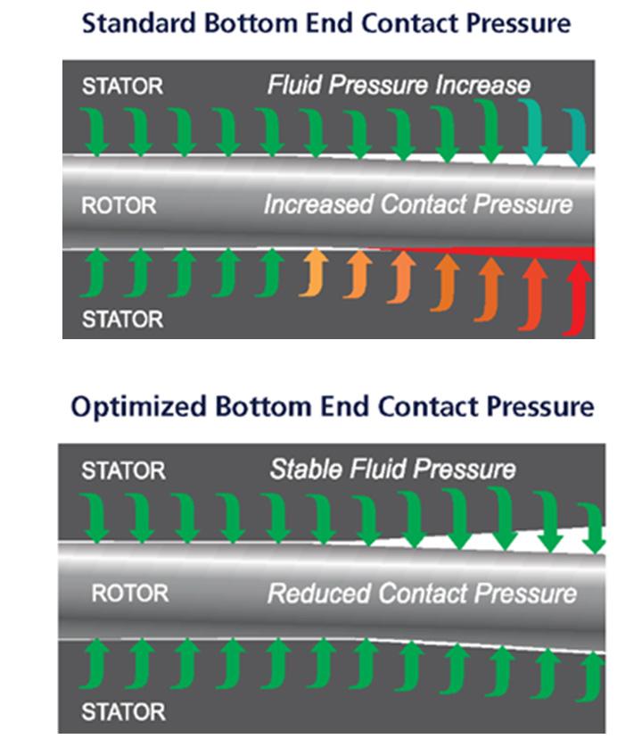
It has long been known that power sections used in downhole mud motors predominantly fail the stator elastomer at the lower end, and that this section of the stator builds up the largest amount of heat. The failure of the elastomer becomes more pronounced as the need to drill at higher efficiencies and associated drilling parameters has become the norm. The power section industry initially responded to these needs by using hard durometer elastomers to improve the differential pressure capability of stators and making high stage count extended length designs. Both of these improvements increase the pressure capability of motors but they did not address the stress concentration at the lower end of the motor. In some cases, the additional pressure capability can damage the lower end of the stator in fewer hours due to the uneven power section loading and the dynamic stresses created by drilling with high parameters and aggressive drill bits.
Development and lab testing
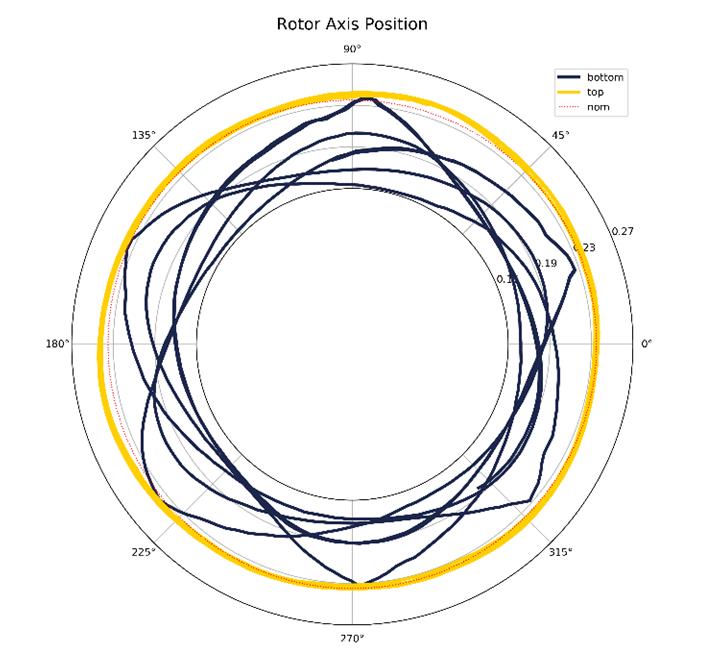
Abaco Drilling Technologies launched a project to document and improve the lower end stresses of the stator in early 2019. The Abaco OPTIFIT patent US 11,421,533 discusses in detail the deflection of power section rotors and stators under differential pressure loads. Devices are used to measure these deflections on an X-Y plane. These deflections give clues to the high stresses seen in the lower end of the power section.
An example of the X-Y location data collected from dyno tests is shown in Figure 1 and reveals the non-ideal procession of the rotor at the power section exit plane. The yellow circles represent the inlet behavior of the rotor and stator; it shows the rotor processing in a smooth design orbit. The lower end of the power section produces many deflection patterns that create deviated rotor orbits causing excess interference with the stator elastomer and destructive vibration (orbit) patterns are repeated.
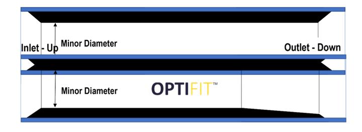
The OPTIFIT feature is used to reduce the high stresses by providing a tapered fit that follows the deflection pattern of the rotor. In doing so, the unintended interference pattern is reduced, friction is reduced, and stress is reduced. An optimum taper is applied that reduces stress yet
still allows enough interference fit to provide maximum power output. Figure 2 shows a simplified comparison of the OPTIFIT stator design when compared to a conventional stator. A graphical depiction from an FEA model showing the reduced stresses in the lower end of an OPTIFIT stator is shown in Figure 3.
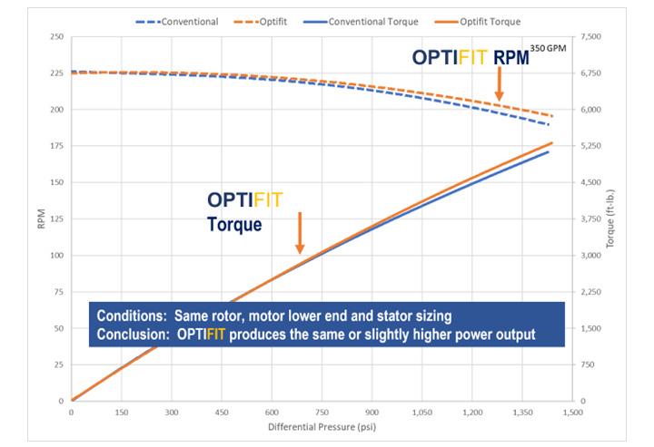
When applying OPTIFIT design principles, we see much improved reliability and dull condition of stator elastomer. Dyno testing has shown that tapering the interference fit pattern improves power section efficiency by reducing friction in the high rotor deflection areas. This is seen at the high load portion of the power curve. OPTIFIT tapered stators consistently show that the torque output remains linear slightly longer than a conventional fit power section. Abaco has conducted numerous tests to validate and quantify the torque output with an OPTIFIT stator. Figure 4 shows a comparison of a typical OPTIFIT power curve when overlaid with the output of a corresponding conventional stator.
Initial field testing
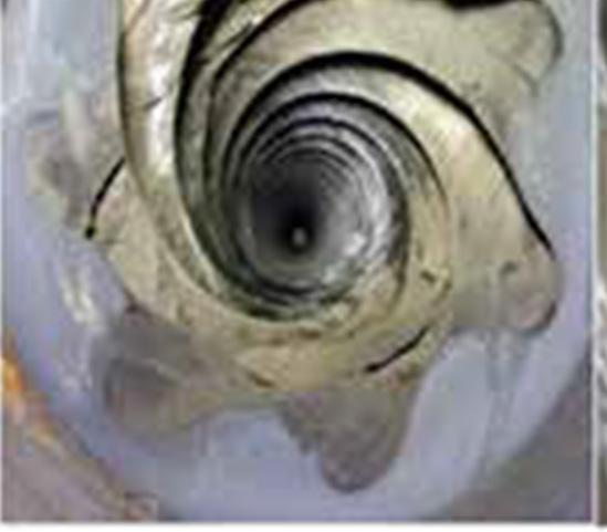
A customer was running an Abaco 700 series power section in a performance drilling application with high parameters and was generating frequent stall events. The results with conventional fit stators were not meeting the operator’s desired completion rate, as 20% of the stators were chunking out severely enough to end the drilling and required replacing the motor to finish the interval. Upon tear-down and inspection of the stators, 75% of the product had significant cracking and at least some chunking. An example of the type of elastomer chunking observed is shown in Figure 5.
Abaco used this as a testing opportunity for the OPTIFIT stator design. The same elastomer was used in the OPTIFIT stator as in the previous runs and the average fit or group sizing of the up-hole end of the stator was the same as the conventional fit stators. Results were compiled for over 30 stator runs and showed that the field failures were eliminated. Tear-down inspection showed that only 15% of the stators had minor chunking or cracking. Due to the increased reliability, average hours on the stators increased 58% and allowing the operator to improve results in achieving their objectives.
Field results
Continuing from the initial field-testing stage, Abaco launched the OPTIFIT product at the end of 2020. This was followed by a period of early-stage commercial production, which saw the introduction of the product to the market and the resulting exponential growth experienced in the ensuing periods, as the product was fully commercialised. To date, the company has delivered more than 10 000 units and has created a database of verifiable field results that provide feedback necessary to further quantify success in the field.
Reliability
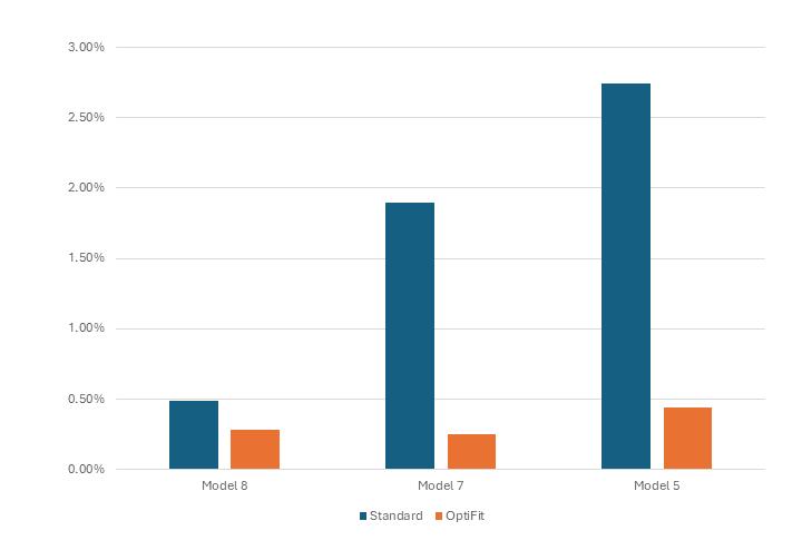
Abaco retains data each year on the production, quality, and reliability of its products. Included in this are the documentation of products returned as part of a warranty analysis, based on the performance of the product in the field. One measure of reliability is to view macro data on products returned that have exhibited instances of stator chunking earlier than anticipated. Comparing the return rates of various models with, and without, the OPTIFIT feature can provide insight into the efficacy of the design.
Early in the commercialisation phase, Abaco created an OPTIFIT version of a highly versatile 8 in. power section that was used in multiple applications in all the major shale basins in the US. Over the course of the past five years, the company has delivered more than 5000 units of this specific 8 in. product to over 30 separate customers. The introduction and proliferation of OPTIFIT stators as an upgrade in this environment offers provides an excellent opportunity to measure the reliability of the
Figure 1. Rotor eccentric motion.
Figure 2. OPTIFIT design illustration.
Figure 3. OPTIFIT stress reduction.
stator on a macro level. In the time frame of our study (from 2019 - 2024) the 8 in. stator returns for the conventional design of this model was a rate of 0.49% of the models delivered. The warranty return rate for the OPTIFIT version of this same stator model was 0.28%. This comparison is shown as Model 8 in Figure 6.
Similar results are found across other models, as shown in Figure 6. Model 7 represents a 6.3/4-7 in. power section that has been used primarily in the Eagle Ford shale trend in South Texas. The warranty return rate from 2019 to present is 1.9% for a standard stator, while the corresponding return rate for OPTIFIT stators of the same model is 0.25%. An additional note here is that in 2024 there were zero returns for the OPTIFIT stator of this model, out of 220 total runs for the year.
Model 5, in the same figure, depicts a high-speed/high-torque 5 in. range power section that is employed extensively in both the Bakken and Haynesville shale plays. The return rates observed here are 2.74% for the standard version of the stator, versus a return rate of 0.44% for the OPTIFIT version of the stator.
In examining this data, it is worth noting that all the results presented here are based on total sample sizes of 2000 or greater for each power section model. Additionally, all the studies depicted are confined to one elastomer type. Further observations within the company’s database show that OPTIFIT stators improve reliability in almost every case. The magnitude of improvement is greatest in power sections that deliver the most power, as well as in the wells that have the highest temperature.
Drilling performance
Revisiting the drilling performance of Model 7 referenced in our reliability studies, we can quantify the improvements in drilling performance. We frequently have stators returned that have performed as expected but which also exhibited a slight amount of elastomer degradation in the form of chunking. This information is all logged and recorded as part of our archived data in our warranty return database. Returning to the data set collected from Model 7, we used a subset that considered only the South Texas – Eagle Ford sections. Additionally, we confined our analysis to only instances in which the interval reached ‘TD’ – a planned end to the section.
A summary of the data, shown in Figure 7, depicts the average depth out and average footage drilled of the conventional 7 in. stators as compared to the 7 in. OPTIFIT stators of the same model (Model 7). The results show that the OPTIFIT stators, on average, drilled 11% further than the conventional version and were generally pulled at depths 19% greater. Another observation of the data showed a greater portion of the OPTIFIT stator runs achieved lateral intervals in excess of 10 000 ft.
Conclusion
From the moment a drilling motor is run in a wellbore, the elements present begin to degrade the assembly, inclusive of the elastomer in the stator. All elastomers are subject to the degradation by the chemicals in the drilling mud, as well as the heat present in the well. This is all exacerbated by the mechanical stresses associated with the delivery of power to the drilling motor. OPTIFIT stators will not eliminate these conditions, nor will they eliminate the degradation to the elastomer that ultimately results in chunking. However, they will reduce the stresses that are present and improve both the life and the reliability of the stator and drilling motor.
OPTIFIT stators have been a significant driver in the advancement of the performance of drilling motors. Since the development of the concept we have been able to define and quantify the benefits provided by the technology. OPTIFIT stators are known to improve the reliability of stators in any directional application: vertical, curve or lateral, as well as in every basin in which it has been applied. The result is longer runs and the ability to drill deeper as the industry moves to longer horizontal wells.
Figure 4. OPTIFIT power curve.
Figure 5. Examples of stator chunking.
Figure 6. Warranty return rates for conventional and OPTIFIT stators.
Figure 7. OPTIFIT performance in the Eagle Ford.
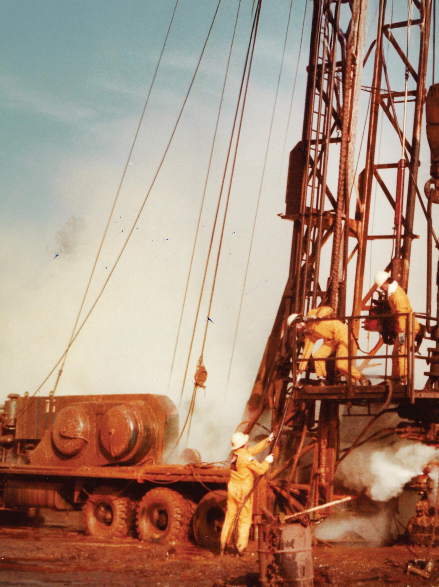
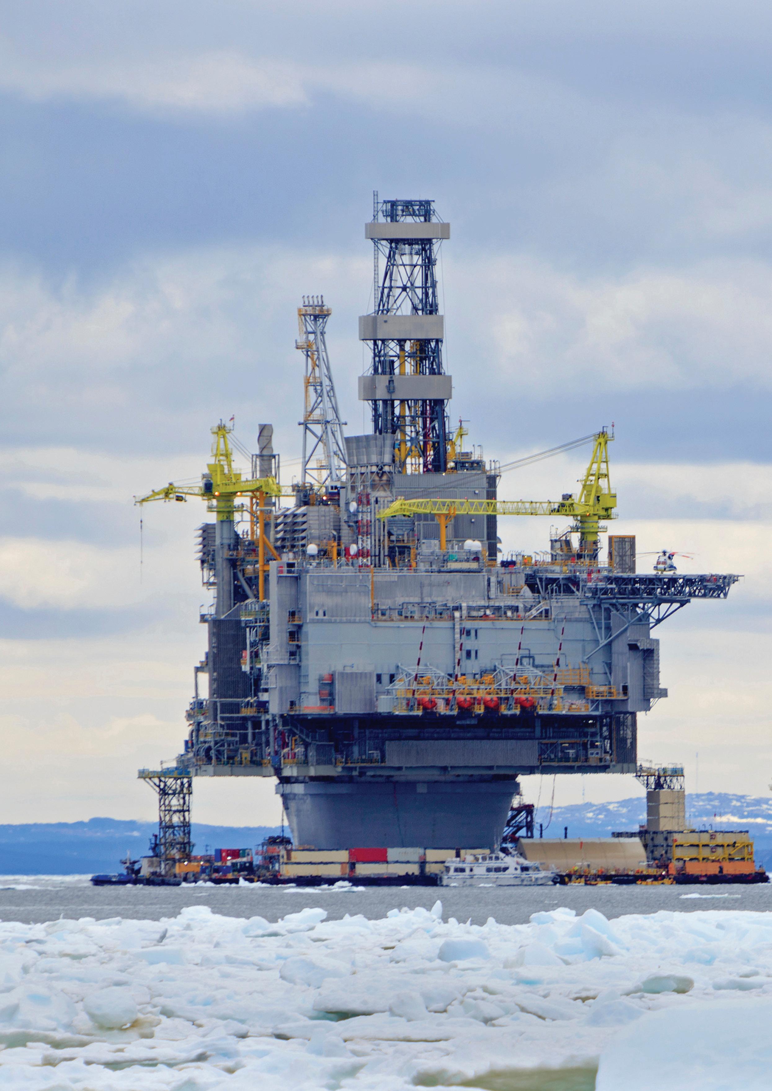
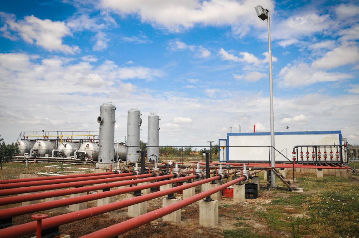
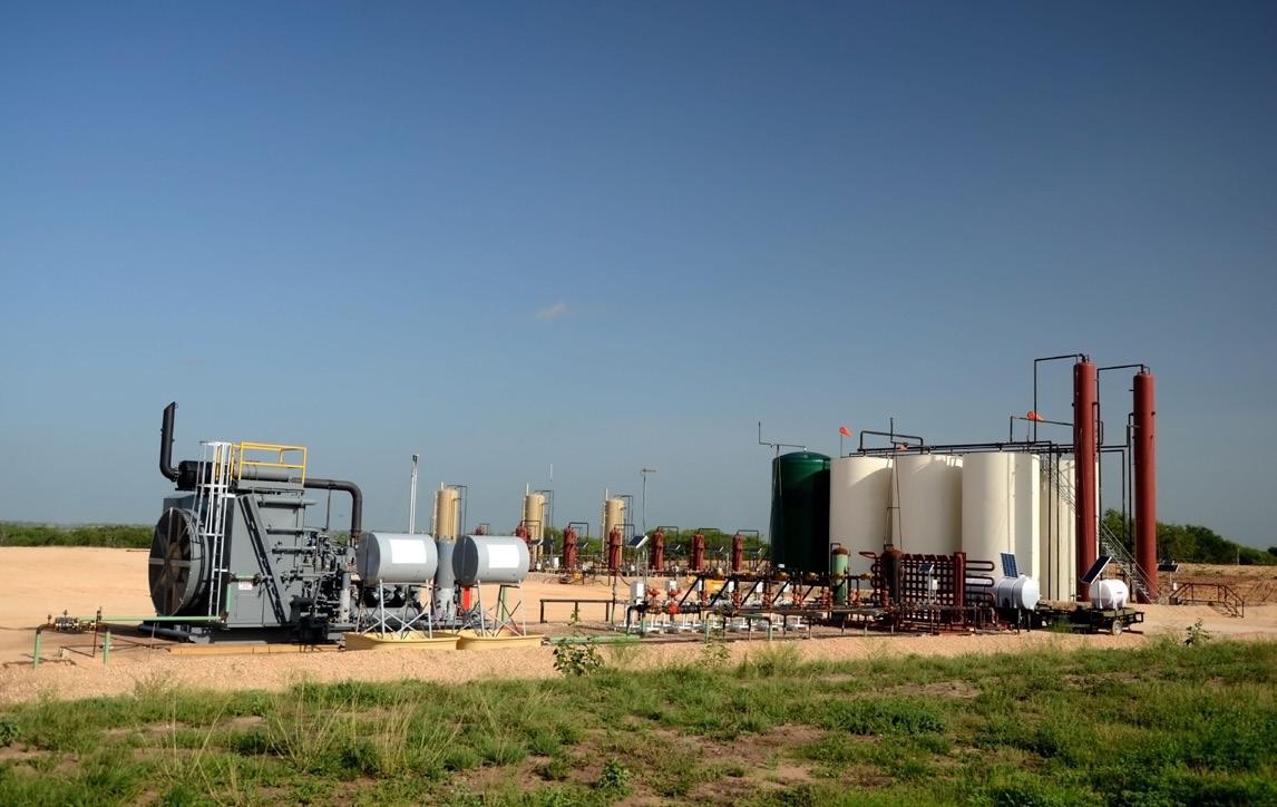
Figure 1. Energy security will take operators to harsher and more restrictive locations.
Leonard Hamill, Operations Director, Pipetech, discusses the issues facing downhole wells in deepwater environments and how the development of new technologies can address these issues.
Global energy security is an ever-present point of contention and discussion. Whether in traditional oil and gas or new energy sources, operators and the diverse supply chain that supports them are united by one common goal: to secure the infrastructure, technology, processes, and people to deliver international energy demand.
The history of the oil and gas industry has been characterised by innovation, technical excellence, and reinvention. Leadership and collaboration have been crucial to overcoming evolving demands and regulations, and these qualities will continue to be front and centre as we move into a new era of energy efficiency. Although the future of renewable energy is promising, traditional
Collaboration is also fundamental in R&D. Cross-industry collaboration can help unlock new solutions to both longstanding issues and emerging challenges. When we work together across the supply chain, we gain a deeper understanding of the most pressing issues facing energy security and how we can collaborate to create the tools, technologies, and solutions that drive progress. An open industry allows us to break down the barriers that often limit innovation, whether accessing funding, having the appropriate resources in-house, or getting the opportunity to test developments in the field.
Flow remediation specialists Pipetech has placed collaboration and R&D at the heart of its latest, industry-first innovation.
Leading the way in flow assurance
A subsidiary of Ramco Pipetech Holdings Limited (RPHL), Pipetech has established a growing presence in the industry thanks to its reputation for delivering flow remediation solutions across applications, including its track record of addressing both topside and subsea oil and gas asset challenges. Pipetech’s catalogue of cleaning technologies has been developed to tackle a wide variety of naturally forming materials that have historically led to costly production downtime and in extreme cases, the premature abandonment of otherwise viable wells.
These materials and deposits, including scale and wax, can and do lead to a decline in production, necessitating well intervention solutions. Light well intervention, such as well cleaning and maintenance, play a vital role in the longevity of production by maximising optimal flow while helping to extending well life and avoiding costly well abandonment.
Traditionally requiring lower costs and producing a quicker turnaround than heavier methods of well intervention, light well intervention solutions are incredibly practical for frequently occurring well issues while also helping with the flow of an oil well.
It is these issues that Pipetech has built a reputation addressing and led to the creation of the Downhole Scale Remediation (DSR) technology.
Case study: DSR development
Inspired by Pipetech’s scale removal experience, the development of the DSR signals an important pivot in tackling scale-related issues within downhole wells in a bid to support the longterm success of existing and upcoming campaigns. Offering an efficient, precise, and more environmentally responsible cleaning solution than previously standardised, the DSR has been developed to support evolving industry needs.
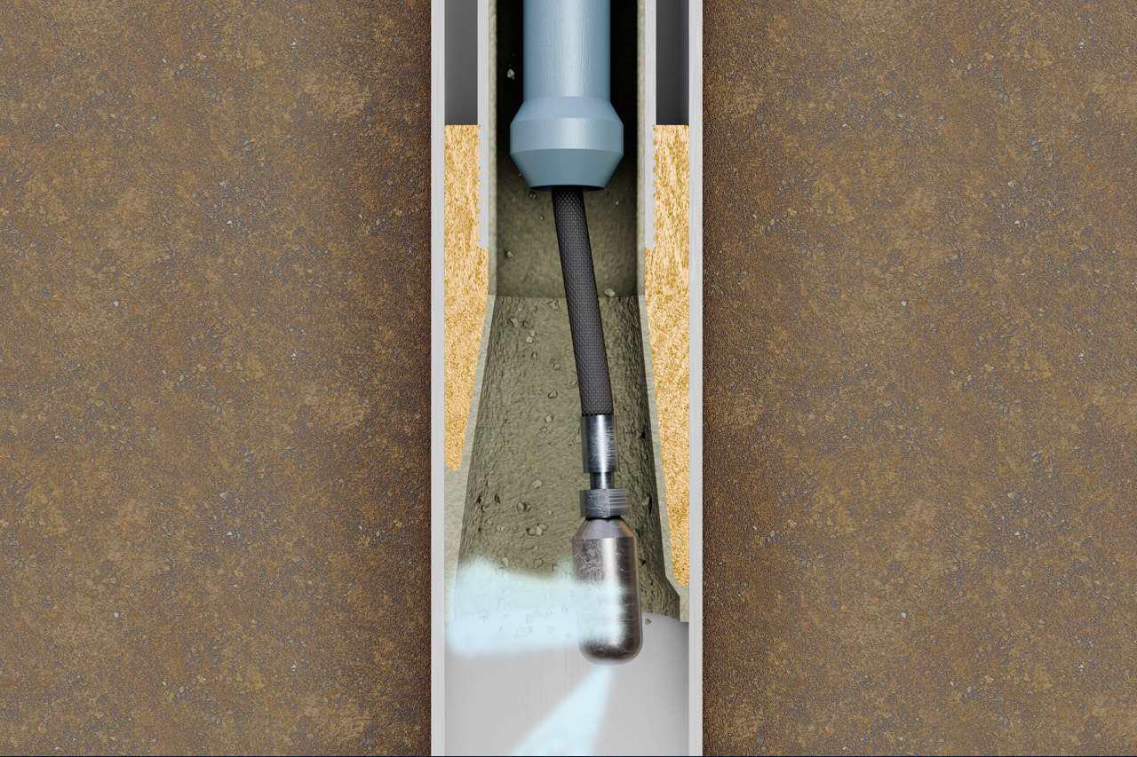
Leveraging a rotational high-pressure water-jetting system, the DSR targets and removes stubborn scale deposits within wellbores, subsurface safety valves and perforations. By cleaning the inside of a wellbore back to the bare metal, the DSR restores wellbore surfaces and addresses common issues which compromise production efficiency or even lead to the risk of well abandonment.
Historically, operators have relied on chemical and mechanical methods to tackle the challenges surrounding wellbore clogging. Looking to the future though, these
traditional approaches are facing increasing scrutiny due to inefficiencies, limitations, and the negative environmental impact they cause. Although chemical treatments are proven to dissolve deposits, they are often hazardous, corrosive, and leave a lasting negative impact on the surrounding environment. Additionally, mechanical tools typically struggle to access complex wellbore geometries, resulting in incomplete cleaning.
Instead, the industry is on a journey towards more advanced and long-term sustainable solutions that align with operational goals and unavoidable environmental responsibilities. By investing in innovative technologies, we can maximise the value of existing assets while navigating uncertainties and contributing to broader sustainability goals.
The DSR itself is a testament to R&D and collaboration. The Pipetech team kickstarted the campaign to bring the DSR to life by working closely with the industry to gain a deeper understanding of the common challenges they were facing and the day-to-day consequences these challenges were having in production. Aiming to support subsea operators with the move into deepwater environments, Pipetech looked at how it could expand its own technology portfolio and transfer its expertise in the topside market into the subsea downhole sector. Following the extensive R&D phase, Pipetech collaborated with key individuals and organisations, including established industry experts, industry bodies, and global operators.
These collaborations led to the DSR achieving proof of concept via comprehensive qualification trials, undertaken at Pipetech’s testing facilities in the north-east of Scotland. Independently verified by third-party consultants, the trials validated the DSR’s potential to support production efficiency and reduce environmental impact. Over the coming months, the DSR’s capabilities will further be demonstrated via a series of field trials on redundant wells in the UK, Norway, and the Middle East. These variations will help to establish the DSR’s adaptability in diverse field conditions.
Looking to the future
As operators seek new ways to extend the life of a well amidst a changing industry and times of uncertainty, the development of innovative technologies (like the DSR) will help to offer compelling solutions that address several of the challenges in deepwater production.
Figure 3. The DSR’s nozzle head rotates to maximise its capacity to clean.
EXHIBITION & CONFERENCE
9-12 SEPTEMBER 2025
FIERA MILANO - MILAN
Powering a sustainable energy future
Join the world’s largest event for natural gas, LNG, hydrogen, climate technologies and AI.
50,000 Attendees
1,000 Exhibitors
1,000 Speakers 7,000 Delegates
BOOK YOUR STAND
150 Countries represented
Join 1,000 exhibitors and connect directly with global procurement teams from EPCs and major energy companies driving LNG and energy infrastructure projects worldwide. Brought to you by
Julian Yeo, United Electric Controls, USA, explores the idea of creating an independent protection layer at the wellhead with SIL certified integrated devices as an effcient instrumentation approach for well pump operations.
Wellsite accidents can be attributed to various causes such as overpressure conditions. A wellknown international insurance company addresses the daunting subject of ‘planning for an oil and gas well control emergency’ this way: “Operators within the oil and gas industry typically manage numerous operational risks. Failure to adequately manage exposures, such as the threat of oil spills, the challenge of finding qualified contractors and the need to protect new workers on the job, could drastically affect an operator’s production goals and bottom line. Though the severity of risk can differ among these exposures, no other threat has the potential to challenge an organisation more than a well control event.” 1 This article explores the idea of creating an independent protection layer at the wellhead with a case study illustrating how a large petroleum company in South America adopted a new approach to pump overpressure protection in remote oilfields.
Risk reduction
Risk reduction experts in upstream oil and gas production are focused on exploring techniques for reducing risk and maximising
uptime. The well control event such as the overpressurisation of flow lines is an area of strong interest, especially because of the significant impact on production and potential for environmental repercussions.
Risk and reliability experts, Henry Johnston and Genebelin Valbuena, prescribed several recommendations for safe wellsite operations in their 2015 white paper entitled ‘An Integrated Approach to Design Hybrid Independent Protection Layers’.2 Some recommendations include:
Ì Having reliable methods such as layer of protection analysis (LOPA) for assessing risk related to well control.
Ì Having a combination of mechanical and instrumented systems used as safeguards known as independent protection layers (IPLs).
Ì A guided way of integrating mechanical and instrumented subsystems into a single protection layer such that it provides sufficient risk reduction for the risk scenario.
The paper opens up a discussion of how innovative pressure instrumentation available in the industry today can contribute quantitatively and qualitatively to risk reduction.
Wellhead independent protection layers
According to the American Institute for Chemical Engineers Center for Chemical Process Safety (AIChE CCPS), an IPL is a combination of mechanical and instrumented safeguards that must be specific, independent, dependable, and auditable3, and provide valid risk reduction. By definition, that risk reduction is limited to 10 on the risk reduction scale. An IPL is valuable because it can help prevent a scenario (e.g., overpressure condition) from escalating to the undesired consequence, without itself being adversely affected by the initiating event. It is also independent of other protection layers like a safety instrumented system (SIS).
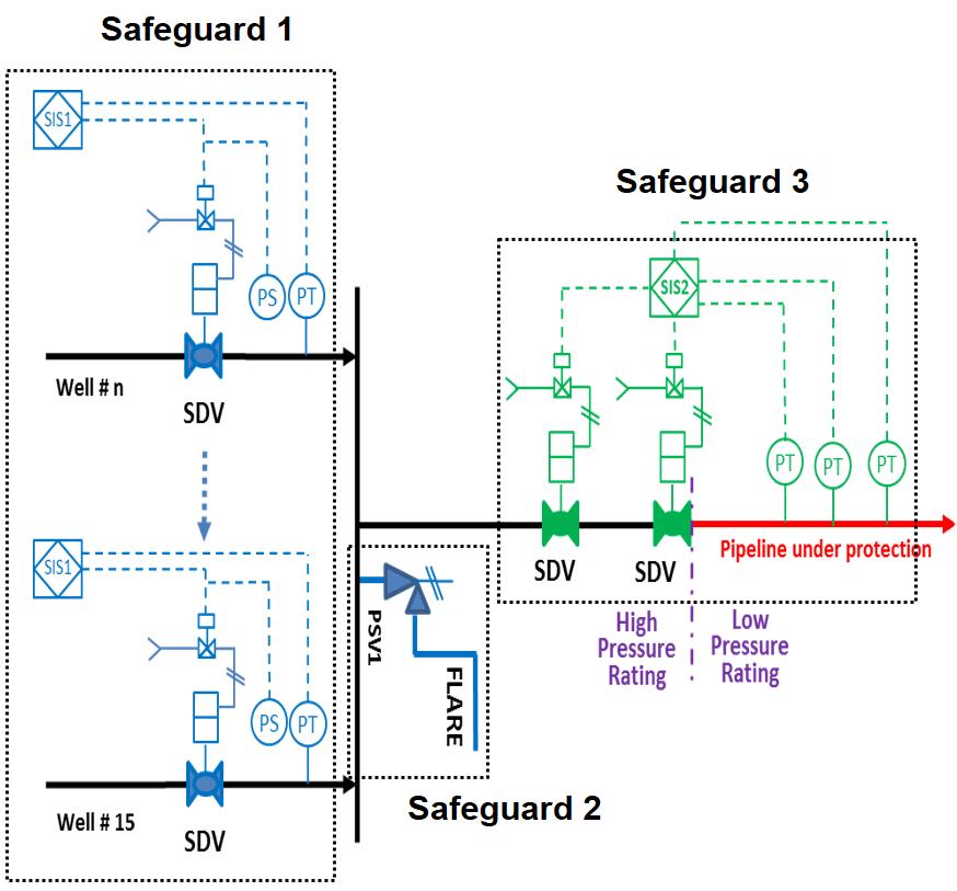
Johnston and Valbuena outline a risk scenario involving the over-pressurising of flow lines from 15 well sources (Figure 1). Employing LOPA to model the risk scenario, they determine the right safeguards, including looking at initiating causes, their likelihoods, and what kind of IPLs might best be employed.
In Figure 1, the authors highlight a non-compliant legacy process that fails to meet the tolerable risk criteria of the operator. The LOPA team considered a combination of three safeguards in order to provide protection for the overpressure of the wells and protection of the low pressure export pipeline. Safeguard 1 defines the boundaries of an instrumented system at the wellhead – a safety instrumented function using a pressure transmitter (PT), pressure switch (PS), logic solver and an emergency shutdown valve (SDV). This combination is intended to automatically isolate any one of 15 wells flowing into the common manifold during an overpressure condition.
Unfortunately, the 15 out of 15 voting dilutes the risk reduction to a degree that Safeguard 1 no longer qualifies as an IPL (i.e. RRF<10). Safeguard 1 fails to meet the ‘dependability/reliability’ criteria of an IPL because the reduction of identified risk is unable to be quantified by a known and specified amount. Since this scenario can be a common concern in remote oilfields, the setup can be adjusted so that Safeguard 1 is qualified as an IPL, which would be a desirable goal.
Proposed solutions
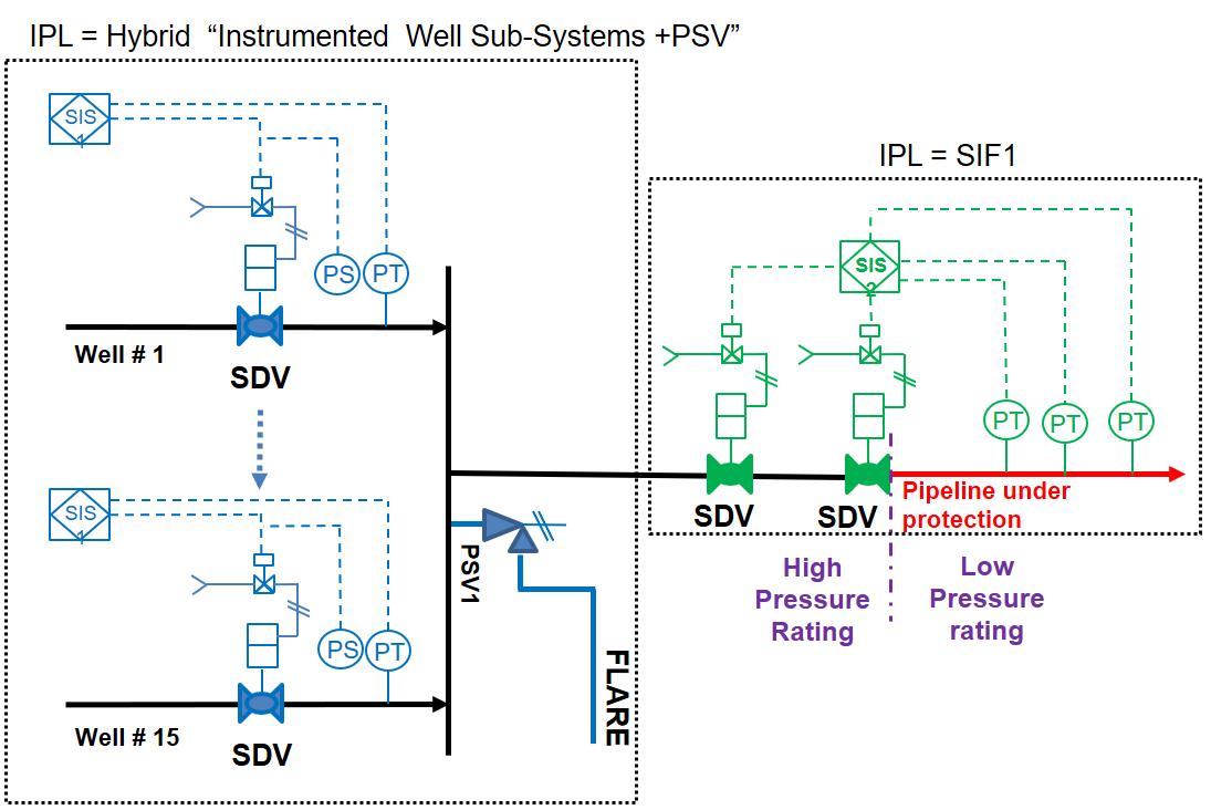
One solution Johnston and Valbuena proposed is to integrate Safeguards 1 and 2 into a single IPL. Safeguard 2 is a mechanical system consisting of a pressure relief valve (PSV) and flare. JohnstonValbuena observed that the combination of Safeguard 1 and 2 can be a valid IPL when the boundaries of the safeguards are re-drawn (Figure 2). When Safeguard 1 and 2 are integrated, the hybrid consisting of the instrumented well sub-system, pressure safety valve and flare achieves the target risk reduction.
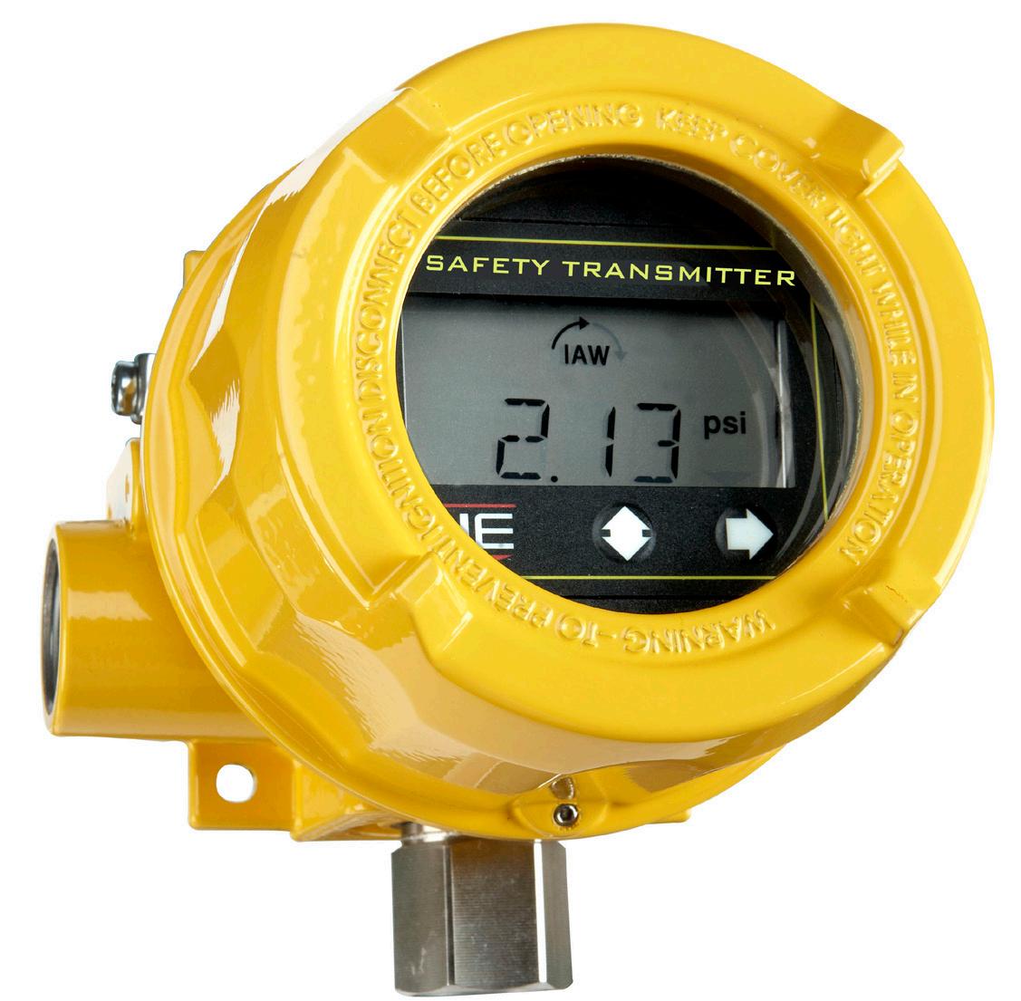
The second solution outside the scope of the Johnston and Valbuena approach is to increase the reliability factor of the instruments (e.g. pressure transmitter, pressure switch) in Safeguard 1. By upgrading devices to safety integrity level (SIL) certified instrumentation, the risk reduction factor (RRF) of the system can be improved, such that the instruments can be deployed in the same conventional setup while qualifying Safeguard 1 as a valid IPL. SIL certified instrumentation can bring about quantitative and qualitative improvements to a wellsite, specifically pump operations.
SIL certified instrumentation for pump overpressure protection
While certified functional safety experts exercise complex quantitative risk assessment (QRA) and develop methodologies and innovative risk reduction approaches, instrument hardware manufacturers have been responding to industry’s needs by designing SIL certified instrumentation (e.g., pressure controls) that
Figure 1. Simplified process diagram of risk scenario at the wellsite. (Diagram courtesy of www.isa.org).
Figure 2. Redrawing of IPL boundarie. (Diagram courtesy of www.isa.org).
Figure 3. SIL certified integrated instrumentation, combining functions of a transmitter, switch and gauge in a single device.
Beyond NPEs Beyond NPEs
Dr. Silke Hoppe and Dr. Cornell Stanciu, Sasol Chemicals, weigh in on the necessity and opportunities of increasing use of narrow-range ethoxylates in the oil and gas industry.
In an era where sustainability is a top priority, many large oil and gas producers find themselves at a critical crossroads. While the industry still has a choice, increasing societal and customer pressures for sustainability are driving companies to seek out alternative solutions. No longer just a trend, sustainability is a guiding force that is shaping corporate strategies across all sectors. Businesses that respond to these pressures are not only meeting the demands of their customers and employees but are also positioning themselves as leaders in a rapidly evolving landscape.
One specific challenge for oil and gas producers is the chemical processes used to expand access to these resources through hydraulic fracturing, commonly known as ‘fracking.’ As regulatory bodies, non-governmental organisations (NGOs), local governments, and consumers increasingly demand environmentally responsible practices, the industry must strongly consider making a conscious choice to begin seeking alternatives that can offer it a pathway to a more sustainable future, ensuring long-term viability and success in a world that prioritises environmental stewardship.
Narrow range ethoxylates (NREs) – a more sustainable alternative
For decades, non-ionic surfactants, particularly nonylphenol ethoxylates (NPEs), have been the standard choice in many oil and gas chemical formulations where controlling oil/water interaction is necessary. NPEs are widely used for their effectiveness in critical fluids employed in drilling, completion, production enhancement and flow assurance. Their popularity stems from their affordability, scalability and consistent performance across various applications. However, despite these advantages, NPEs are now facing increased regulatory scrutiny due to their significant environmental drawbacks.1 Aquatic and animal studies have shown that NPEs are toxic to fish and are associated with reproductive and developmental effects in rodents.2 This has led to bans not only in certain regions but also in consumer-based markets and some industrial processes as concerns grow about their long-term impact on ecosystems and human health.
The global regulatory landscape surrounding chemicals like NPEs is evolving rapidly, driven by these growing concerns about environmental impact and worker safety. For example, the European Union’s REACH regulation (Registration, Evaluation, Authorisation and Restriction of Chemicals) imposes strict limits on NPE concentrations, signaling a global shift towards more ecofriendly alternatives. Similarly, in North America, the Environmental Protection Agency’s (EPA) proposed Significant New Use Rule (SNUR) under the Toxic Substances Control Act (TSCA) and California’s stringent limitations on NPEs in detergents reflect this trend.3
In response to these challenges, the industry is proactively seeking alternatives. Though there are several surfactant chemistries a formulator can evaluate, the first-choice alternatives with similar performance, availability and price are non-ionics based on linear or branched alcohols. These types of surfactants are generally classified into two categories: broad-range ethoxylates (BREs) and narrow-range ethoxylates (NREs). Based on the production catalyst used and the resulting distribution of ethoxymers, BRE and NRE surfactants offer a performance profile comparable to NPEs while significantly reducing the environmental impact of the oil and gas production fluids.
NREs represent a significant step forward for the oil and gas industry. There are performance and sustainability advantages associated with NREs that make them the preferred choice by operators wanting to demonstrate their commitment to environmental stewardship and improve worker safety while
Figure 1. Ethoxymer distribution in conventional BREs (green curve) and NPEs (purple curve) compared to NRE surfactants (blue curve). The NRE contains more of the target ethoxymer desired (in this case the 9-mole) compared to NPEs or BREs. There are several advantages to removing the low- and high-mole portions of the ethoxymer distribution. Source: Sasol Chemicals.
potentially reducing operational costs associated with handling and disposal.
As research and development efforts continue to expand the range of NRE applications and optimise their performance, these advanced surfactants are poised to play an increasingly vital role in responsible oil and gas production.
A closer look at NRE advantages
NREs are a type of surfactant made with special catalysts and offer distinct advantages over NPEs in certain oilfield applications:
Ì Reduced environmental impact: NREs do not use the endocrine-disrupting nonylphenol alcohol starting material which results in the significant aquatic and human health concerns associated with NPEs.3 NREs are biodegradable and produce less harmful byproducts upon degradation than NPEs, minimising their environmental footprint and reducing the risk of long-term ecological damage with use in oil and gas productions. This characteristic aligns with the industry’s increasing focus on sustainable practices and reducing its impact on water resources.
Ì Enhanced performance: the narrow ethoxymer distribution of NREs allows for optimised performance in specific oilfield applications. They have the ability to achieve precise hydrophilic-lipophilic balance (HLB), which is a number that indicates the relative hydrophilicity/hydrophobicity among surfactants. The narrow ethoxymer distribution also makes NREs highly effective in applications requiring clean separation interfaces, such as demulsification or for designing spacer fluids or in applications when more precise HLB values are helpful, such as organoclay activation.
NREs exhibit properties that support handling processes in oil applications:
Ì Lower volatile organic compound (VOC) and odours: for example, by removing low-mole ethoxymers, NREs reduce free alcohol content, resulting in lower VOC emissions and reduced odour.
Ì Low melting points: by removing the high-mole ethoxymers, NREs have also proven to have lower melting points compared to BREs, making them safer and easier to handle for oilfield personnel. This can be advantageous in colder environments where maintaining fluid properties at lower temperatures is critical or where heating is not available. These characteristics can also help reduce energy consumption and potentially lower transportation and storage costs.
NREs in action: key oilfield applications
The advantages of NREs can be applied to various oilfield applications. Two areas where NREs are making a significant impact are organophilic clay activation and demulsification/ emulsion breaking.
Ì Organophilic clay activation: fracking operations can use polymer slurries that utilise organophilic clays as viscosifiers to maintain proper fluid properties to carry the proppant under challenging downhole conditions. NREs effectively activate these clays, ensuring optimal viscosity and stability of the slurry. Their precise ethoxymer distribution ensures efficient interaction with the clay, leading to improved performance compared to BREs, which may require higher concentrations to achieve similar results.
Ì Demulsification/emulsion breaking: the separation of oil and water is a critical step in oil production. Emulsions, however, often form during the oil production process, hindering separation efficiency and requiring specialised demulsifiers
to break them down. NREs excel in this role, effectively breaking emulsions and facilitating faster flowrates. This is particularly evident during flowback operations.
Case study
Alpha Energy Technologies LLC (AET), an emerging leader in the oilfield industry, has seen several advantages with NREs. Incorporating the narrow distribution additives into their products has enabled their end-users to increase flowback rates significantly after completion by reducing problematic emulsions often observed with BREs. According to AET representatives, narrow distribution additives have enabled them to design for and customise this aspect of their products to maintain a desired HLB throughout the initial production timeframe.
Meeting the demand for more sustainable solutions
The demand for more environmentally sound solutions in the oil and gas industry is not limited to surfactants. Operators are increasingly seeking ways to reduce their overall environmental footprint across all aspects of their operations. This includes minimising water usage, reducing greenhouse gas emissions and adopting technologies that promote responsible resource management. For example, the American Petroleum Institute is supporting its members with sustainability driven certifications, safety programmes and industry-led initiatives dedicated to improving the industry’s environmental performance.
The incentive to switch to alternative solutions like NREs is also driven by clean ingredient and profile listings. For example, NREs typically have higher ranked safety, health and environment (SHE) profiles. Additionally, a number of NREs are listed on CleanGredients list of products that meet the US EPA’s Safer Choice Standard.
To support the responsible use of NREs, particularly in sensitive environments like the North Sea, Sasol has secured approvals for specific NRE formulations supported by its NOVEL® technology. This includes assessments by the Centre for Environment, Fisheries and Aquaculture Science (CEFAS), which play a key role in evaluating the potential environmental impacts of offshore activities.
The adoption of NREs aligns perfectly with this broader industry shift towards more sustainable solutions. By choosing NREs over traditional, more harmful surfactants, oil and gas companies can prove their dedication to environmental responsibility and contribute to a cleaner energy future.
Finding the right partners to drive adoption of NREs
Successfully integrating NREs as a standard practice within the oil and gas sector requires a collective commitment to progress from all stakeholders. By sourcing and collaborating with partners who are at the forefront of NRE innovation, operators can leverage external expertise and capabilities that will help drive this transition.
Recognising that every oilfield presents unique challenges and requirements, it is critical to work with partners that focus on customising surfactant formulations to meet the specific needs of each well. This approach will achieve optimal performance while minimising environmental impact.
Finally, innovation extends beyond formulation. Partners who are continually expanding the use of NREs across various oilfield applications will unlock new performance benefits and set the standard for more environmentally responsible surfactants.
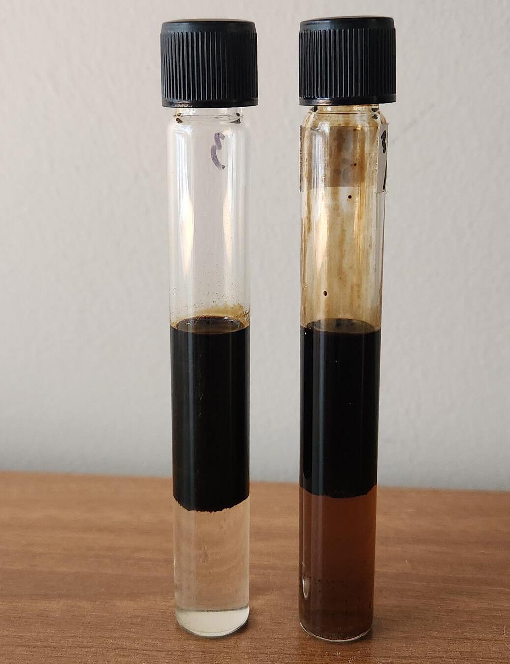
Figure 2. NREs and NPEs in demulsification applications. Image A on the left using NREs shows superior phase separation and water clarity compared to that of the Image B on the right using NPEs. This highlights the efficacy of NREs in the crucial demulsification process.
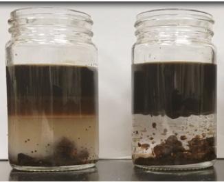
Figure 3. Difference in separation and clarity of the lower aqueous phase in the two jars following a bitumen extraction from a solid sample. In the left jar, BRE surfactants were used while in the jar to the right NRE surfactants were utilised. Sharp phase separation and better water clarity were achieved using the NRE surfactant.
References
1. ChemSafetyPRO: Nonlyphenol and Nonylphenol Ethoxylates: https://www. chemsafetypro.com/Topics/Restriction/REACH_annex_XVII_Nonylphenol_ and_Nonylphenol_Ethoxylates.html
3. California Department of Toxic Substances Control: https://dtsc.ca.gov/scp/ nonylphenol-ethoxylates-npes-in-laundry detergents/#:~:text=Domestic%20 and%20foreign%20manufacturers%20of,products%20by%20November%20 30%2C%202024.
Geir Melhus, Vice President Operations, and Johannes Nesse, Field Service Manager, TCO, Norway, examine the process of developing a new type of shallow set barrier plug, and its implications for upstream technology.
Apartner company challenged TCO to develop a new type of shallow set barrier plug that could be deployed on wireline, remotely opened and even retrieved after opening to retain a full wellbore. The resulting R&D project successfully solved the challenge. It also ushered in technological innovations that migrated successfully to TCO’s wider product portfolio.
The case was a drilling campaign for a large North Sea field development. Eight wells were planned for drilling, but the wells needed to be suspended for up to a year while waiting for the vertical Christmas trees (VXTs) to arrive. The operator needed to suspend the wells in a manner that was safe, cost effective and did not limit future
operational options. The ability to optionally retrieve the entire plug after opening was regarded as additional benefit.
A new option
At that time, retrievable barrier plugs were not an option in the production portfolio for the company. For shallow barriers, they had relied on the first generation of the disappearing tubing hanger plug (DTHP) for years as a tried and tested barrier plug with remote open features and bypass capabilities. The first generation DTHP plugs were limited in design due to small ID through the assembly, which was not ideal for future well intervention operations. The restricted ID
into the plug casing sleeve and sealed tight. The inherent property of security glass is that it can withstand high differential pressure but will shatter when impacted sharply by an object. Just as car windshields or glass tables will. It was now imperative to design a fail-safe mechanical solution for plug opening.
Making the right moves
So instead of making the sharp object come to the glass, TCO looked at solutions for making the glass move towards the sharp object. As the glass is a fairly large mass at a minimum of 4 in. in diameter, a certain amount of force was also needed to get the glass moving at the necessary momentum required for breaking.
Of course, being in an oil well, applied pressure from topside provided the necessary force for moving the glass. As the E-trigger records the completed opening sequence through pressure differentials, the release mechanism supporting the glass plug is opened. The plug, no longer fixed in place, reacts to the applied pressure, gains momentum and is shattered when impacting the stationary breaking mechanism.
Adding new moving parts to a product with size restrictions proved to be the biggest engineering challenge. New parts also require additional testing to ensure that the additions meet the ISO standards requirements. Testing completed; the new design has worked flawlessly. The redesigned opening mechanism has proven to be the most consequential part of this R&D project for TCO. It has migrated to other products in their barrier plug portfolio, which is now 90% non-explosive. Explosive plugs are still used for special purposes, mainly in the North Sea, but are now a smaller part of TCO’s installations.
Six month suspensions
The DTHP-R plugs were set as shallow barriers on all 8 wells using wireline. When entering the seal area, plugs were jarred down and locked in place before the drilling platform completed the campaign.
The operator had specified that plugs should be operable up to one year after installation. As the DTHP-R is battery operated, lifetime is dependent on both time and temperature, with temperatures as the most limiting factor. Due to a shallow installation in low temperatures, this ensured that a one-year suspension was well within operating capabilities.
The plugs were suspended for six months from installation. Upon successful installation of the VXTs, all plugs were remotely opened using the pre-determined pressure key. With completion done and plugs cycled open, the wells were producing with rates from 1000 – 2000 boe/d.
Full flexibility for the operator
The DTHP-R can be installed with both wireline or drill pipe and then later be cycled open remotely or pulled mechanically. For this campaign three DTHP-Rs were successfully retrieved during a planned well intervention at a later stage. Removal is done by running the retrieval tool that latches onto the plug assembly, disengages the locking dogs, and pulls the entire plug assembly out of hole, ensuring the full bore required by the operator. The remaining five DTHP-Rs are verified to still be in the locked positions in the well with no indication of shifting.
This is the main feature of the DTHP-R: The barrier plug gives the operator full flexibility in well operations. Either leave the plug assembly in place as barrier, cycled open for production or completely removed to preserve the full wellbore in the case of future operations.
About the authors
Ì Geir Melhus has over 30 years of experience in the energy sector. He has worked in drilling and completion with perforations as a specialty with Schlumberger. For TCO he has held roles in management and is now VP Operations.
Ì Johannes Nesse has 15 years of experience in the oil industry, mainly related to completion and intervention. Johannes has worked in various roles within TCO and is now Field Service Manager – Completions.
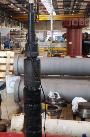
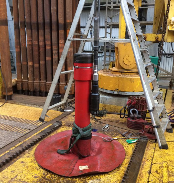
Figure 4. DTHP-R components at supplier facility.
Figure 5. From testing procedures at the Ullrig test facility in Stavanger, Norway.
Mike Brown, Blackline Safety, Canada, outlines the benefits of remote monitoring technologies when overseeing wellsite operations.
Embracing remoteness
In the world of oil and gas extraction, remote wellsite monitoring is critical to ensure operational efficiency and environmental safety. With wellsites located in remote, difficult-to-access or inaccessible areas, traditional monitoring methods can be challenging, costly, and sometimes ineffective. This is where the advent of remote monitoring technologies comes into play, offering a more practical and efficient approach to overseeing wellsite operations.
One of the key challenges in wellsite management is the ability to promptly detect and respond to leaks. Leak detection is not only crucial for maintaining operational integrity, but also plays a vital role in protecting the environment. Unchecked leaks can lead
to significant environmental damage and financial losses due to wasted resources and potential regulatory fines. Unchecked leaks can also pose a safety hazard for workers when they arrive onsite, as they could be entering a potentially dangerous and volatile situation with no advance notice.
Leak detection and repair (LDAR) programmes are required and are evolving in most jurisdictions. More than 50 federal regulations require businesses to have a formal LDAR programme or mandate the use of an LDAR methodology. LDAR is defined by the US Environmental Protection Agency (EPA) as “a work practice designed to identify leaking equipment so that emissions can be reduced through repairs.” According to the EPA LDAR Guide1 (Section 3.0, P.3), leaking equipment emits an estimated 70 637 t of volatile organic compounds (VOCs) per year, with 600 - 700 t coming from leaking equipment in each refinery or chemical plant.
Emerging remote wellsite monitoring and leak detection technologies provide a solution to challenges associated with leak detection. They enable operators to continuously monitor wellsite conditions from afar using various technological tools. This enhances the ability to respond quickly to any irregularities, such as equipment malfunctions or leaks, minimising potential risks and ensuring compliance with environmental regulations.
Traditional wellsite monitoring methods
Traditional wellsite monitoring methods have played a crucial role in the oil and gas industry for decades. Relying heavily on manual labour and direct observation, they have been integral
in ensuring the safety, efficiency, and productivity of oil and gas extraction processes.
Visual inspection
The most fundamental wellsite monitoring method is visual inspection. Engineers and technicians physically visit the site to check equipment, identify signs of wear and tear, and check for dead grass (which indicates a leak) or any visible leaks or damage. Visual inspections are essential for routine maintenance to provide direct, real-time feedback on the condition of the wellsite. However, this method is labour intensive and subject to human error, limiting its effectiveness, especially in remote or harsh environments. In these environments, helicopters can perform visual inspections from the air, yet this method can cost upwards of US$1 million annually per site, depending on location and inspection requirements.
Manual gauge reading
Manual gauge reading involves checking mechanical gauges installed on various equipment to measure parameters such as pressure, temperature, and flowrate. This method allows operators to monitor operational conditions and make adjustments as needed. Despite its simplicity, manual gauge reading is timeconsuming and can be inaccurate, as gauges need regular calibration and maintenance.
Periodic sampling
Periodic sampling of oil, gas, and water from wells involves analysing samples in laboratories to assess properties like viscosity, gas composition, and the presence of contaminants. This method is great for understanding reservoir behaviour and planning extraction strategies, however, sampling is a sporadic process and does not provide continuous monitoring, which can result in delayed responses to changes in well conditions.
Acoustic listening tools
Acoustic listening tools are used to detect underground sounds associated with fluid movement and machinery operations. Operators use ground microphones and listening devices to identify anomalies such as leaks or equipment malfunctions. These tools can be useful for early leak detection, but their operation requires skilled personnel and regular maintenance, and can be affected by surface noise and environmental conditions.
Pressure and temperature charts
Recording pressure and temperature over time using chart recorders has been a longstanding practice. These charts help to understand well performance and identify potential issues like blockages or leaks, yet provide only a historical view and lack real-time data or analysis capabilities.
SCADA systems
Supervisory control and data acquisition (SCADA) systems collect data from various sensors which is transmitted to a central control room. SCADA systems improve data collection and processing, but are limited by their reliance on wired networks and need for on-site sensors and equipment.
Advanced wellsite monitoring methods
In recent years, the industry has been shifting towards more advanced and automated monitoring solutions.
Figure 1. Remote processing operations.
Figure 2. Remote production site.
These technologies offer continuous, real-time monitoring capabilities and higher accuracy, reducing the need for manual intervention. Remote monitoring consists of a range of tools to collect and transmit data, which greatly enhances operational oversight.
Sensors and internet of things (IoT)
Sensor technology has become a cornerstone of remote monitoring, measuring parameters such as pressure, temperature, and flowrate, and providing critical data for assessing wellsite conditions. IoT technology interconnects these sensors, allowing for the seamless collection and transmission of data, and significantly improving real-time data acquisition and decision-making for wellsite operations.
Advantages of IoT-based monitoring
` Real-time data collection and scalability.
` Enables direct-to-cloud continuous monitoring, leading to quicker response times and more informed decision making.
` Portable IoT area gas monitors are easy to deploy and transportable as needed, without requiring expensive fixed infrastructure.
Disadvantages of IoT-based monitoring
` Dependence on network connectivity.
` Vulnerability to hacking and data breaches, emphasising the need for robust security protocols.
Satellite monitoring
Satellite technology offers wide-area surveillance, essential for monitoring extensive pipeline networks and remote wellsites. Advances in satellite imagery allow for higher resolution images and more frequent updates. Satellite data, integrated with geographic information systems (GIS), can effectively monitor changes in wellsite conditions over time, even in inaccessible locations.
Advantages of satellite monitoring
` Can cover vast areas.
` Works in remote locations.
Disadvantages of satellite monitoring
` Resolution and latency issues can be significant.
` Satellite imagery may not always provide the level of detail necessary for certain monitoring tasks, such as leak detection.
` Delays in data transmission.
Drone monitoring
Drones have become increasingly popular for wellsite monitoring, offering high-resolution aerial imagery and the ability to inspect hard-to-reach areas. Drones equipped with thermal cameras and other sensors can identify leaks that might be invisible to the naked eye. Drone surveillance can drastically reduce the time and cost associated with traditional inspection methods, while improving safety by minimising human exposure to hazardous environments.
Advantages of drone systems
` High-resolution imagery and flexibility to gather detailed information about wellsite conditions.
` The evolving regulatory landscape and restrictions have the potential to affect drone usage.
Infrared and laser monitoring
These techniques involve detecting changes in thermal patterns or gas concentrations around pipelines and equipment. Infrared cameras can visualise gas leaks as plumes of warmer air in cooler surroundings, while laser-based systems can detect specific gas molecules at low concentrations.
Advantages of infrared monitoring
` Infrared can identify gas leaks from a distance without risking direct contact with the gas.
` Real-time visualisations of gas plumes make it easier and faster to locate the source of leaks.
` Infrared is sensitive to a variety of hydrocarbon gases.
Disadvantages of infrared monitoring
` Infrared is affected by environmental factors like rain, fog, or high winds, which can interfere with accuracy.
` It requires a clear line of sight to the gas plume, since obstructions can hinder effectiveness.
` There is a high initial cost.
` The technique requires training and expertise.
Advantages of laser monitoring
` High sensitivity and can detect specific gases, even at very low concentrations.
` Can detect gas leaks over long distances.
` Allows for quick response in case of a leak.
` Can quantify the concentration of gas, providing valuable data for assessing the severity of leaks.
Disadvantages of laser monitoring
` Systems are complex and very expensive, both in terms of initial setup and maintenance.
` A clear path is required between the detector and gas source.
` There is a limited detection range for certain gases, particularly a broad range of hydrocarbons.
` The technique requires specialised training and expertise.
Emerging technologies
The EPA LDAR Guide (Section 4.5, P.8) estimates that an effective LDAR programme can save companies US$730 000/yr in product loss alone.1 It also greatly reduces the risk of spill cleanup, which can cost millions or billions to remediate.
Emerging technologies such as Blackline Safety’s EXO portable area monitor are key in implementing cost-effective LDAR programmes. From data analytics to automated sensor technology and easy-to-use portable leak detection solutions, emerging technology is changing the way companies monitor remote wellsites, making it easier and more efficient to find out what is happening and respond accordingly. The solution allows companies to log in from anywhere in the world and see live and historical events and readings, check gas levels, and change device configurations.
Data analytics and automated reporting
The increase in data that comes with more advanced remote wellsite monitoring is changing the way companies make
decisions. Blackline Safety, for example, offers automated reporting, which helps organisations get a complete view of worker and site safety without having to wait for manual collection of usage data and gas readings. The insights gleaned from data analytics and automated reporting help optimise safety and efficiency while reducing risk, and give workers advance notice of dangerous conditions before they arrive at a wellsite.
Reporting also directly feeds into records maintenance – a critical element to an effective LDAR programme. The EPA LDAR Guide1 (Section 7.12, P.26) states that “well-kept records may also indicate that the LDAR programme is integrated into the facility’s routine operation and management.”
AI-based analysis
Artificial intelligence (AI) is increasingly being used to interpret the vast amounts of data generated by remote monitoring systems. AI algorithms can help predict equipment failures, allowing organisations to optimise maintenance schedules and reduce downtime while improving site safety. AI also enables predictive analytics, allowing operators to use gas concentration trends to anticipate and address potential leaks and gas exposures before they escalate.
Wireless and energy-efficient monitoring
Making use of direct-to-cloud IoT technology, remote monitoring systems are becoming more energy-efficient and less reliant on fixed infrastructure and traditional power sources. Blackline’s EXO, for example, can connect to both cellular and satellite networks. Paired with real-time connectivity and GPS location-enabled technology, it is easier than ever for companies to remotely monitor where and when leaks may be happening so they can respond immediately.
EXO also integrates long battery life, solar panels, and wireless communication systems, which not only reduces the environmental footprint of the operation, but also ensures
continuous operation in areas where power availability is a challenge.
Automated sensor technology
The automated gas detection technology built into the EXO portable area monitor reduces the need for physical site visits (customers report saving approximately US$8000 per site, per year, as a result), while providing continuous wellsite monitoring. The ability to automatically bump test and calibrate the monitor without needing to be physically onsite ensures gas detection devices are compliant with all regulations while allowing companies to manage remote wellsites more efficiently. Real-time gas notifications from automated sensor technology can rapidly accelerate leak detection and repairs.
Portable area gas monitoring
Portable area gas monitoring technology allows companies to implement LDAR processes to ensure compliance and avoid penalties at remote wellsites. The easy-to-use drop-and-go EXO gas monitors operate at a significantly reduced cost compared to fixed systems. Built for extreme weather conditions, EXO offers companies the flexibility to move monitors around where they are needed most.
Conclusion
Environmental considerations are increasingly critical in selecting remote wellsite monitoring technology. Emerging portable and wireless devices help reduce carbon footprints of oil and gas operations by minimising the need for travel. Paired with automated remote sensor technology, organisations can proactively monitor sites, and detect and manage gas leaks in a way that maximises employee safety while minimising environmental impact.
As more innovative and lower cost options become available, organisations can continually improve their wellsite safety and environmental compliance, while maintaining or reducing their operational costs.