

A podcast series for professionals in the downstream refining, petrochemical, and gas processing industries

A podcast series for professionals in the downstream refining, petrochemical, and gas processing industries


Sponsored by

EPISODE 4
Rasmus Rubycz, Market Manager for New Energy at Atlas Copco Gas and Process, considers how heat pumps as an industrial technology are gaining greater attention as a result of the increased drive for sustainability, and the challenges and opportunities of electrification of process heat.
EPISODE 5
Mike Logue, Owens Corning Business Director – Specialty Insulation, delves into factors that can support the performance, safety, and longevity of insulating systems installed in hydrocarbon processing environments, including cryogenic facilities.
EPISODE 6
Leakhena Swett, President, ILTA, and Jay Cruz, Senior Director of Government Affairs and Communications, ILTA, consider the importance of trade associations and industry collaborations.
EPISODE 7
Susan Bell, Senior Vice President within Commodity Markets – Oil, Rystad Energy, discusses the impact of trade wars on global oil demand and oil prices, in light of recent US trade tariffs.


Chris
Francisco

Drilling through hard, aggressive rock formations can generate excessive torsional vibrations in your bottomhole assembly (BHA). Left unchecked, these vibrations can limit penetration rates, shorten tool life, and lead to wellbore instability. The GuardVibe™ high-frequency torsional oscillation dampener from Baker Hughes takes a holistic system approach to eliminate critical torsional vibrations throughout the BHA. By dissipating vibrational energy in the BHA, GuardVibe benefits your drilling operations in several ways.


Across energy and critical infrastructure, we bring expertise where complexity is highest. With globally local teams and proprietary technologies unmatched in the sector, we move projects forward, no matter the challenge.
We’re here to partner on how our specialist welding and coating solutions can help you power tomorrow.


ADNOC has announced multiple agreements with US energy majors during the UAE-US business dialogue with US President Donald Trump. The agreements will potentially enable US$60 billion of US investments in UAE energy projects across the lifespan of the projects. They include a landmark field development plan with ExxonMobil and INPEX/JODCO to expand the capacity of Abu Dhabi’s Upper Zakum offshore field through a phased development. ADNOC also signed a strategic collaboration agreement with Occidental to explore increasing the production capacity of Shah Gas field’s capacity to 1.85 billion ft3/d of natural gas, from 1.45 billion ft3/d, and accelerating the deployment of advanced technologies in the field.
The agreements reinforce the shared commitment of the UAE and US to maintaining global energy security and the stability of energy markets. The enterprise value of UAE energy investments into the US is set to reach US$440 billion by 2035, as part of the UAE’s US$1.4 trillion investment plan into the country.
bp Trinidad and Tobago (bpTT) has announced that the Mento development has safely delivered first gas through connection of the initial discovery well and the drilling campaign for the remaining seven gross wells on the platform will now begin. Mento is a 50/50 joint venture between EOG Resources Trinidad Ltd (EOG) and bpTT, with EOG as the operator. The development features a 12-slot, attended facility that is located in acreage jointly licensed by bpTT and EOG off Trinidad’s southeast coast. Mento is one of bp’s 10 major projects expected to start up worldwide between 2025 and 2027 that bp announced earlier this year as part of its strategy to grow the upstream. Production from Mento will make a significant contribution towards the 250 000 boe/d combined peak net production expected from these 10 projects.
CNOOC Ltd has announced a major oilfield discovery of Huizhou 19-6 in the deep and ultradeep plays of the South China Sea, which adds over 100 million t of oil equivalent in-place. Huizhou 19-6 oilfield is located in the eastern South China Sea, with an average water depth of approximately 100 m. The main oil-bearing plays are Paleogene Enping Formation and Wenchang Formation, and the oil property is light crude. The discovery well HZ19-6-3 was drilled and completed at a depth of 5415 m, which encountered a total of 127 m oil and gas pay zones. The well was tested to produce 413 bpd of crude oil and 2.41 million ft3/d of natural gas. Through continued exploration, the proved in-place volume of Huizhou 19-6 oilfield has exceeded 100 million t of oil equivalent.
Amplus has selected the Astican Shipyard in Las Palmas de Gran Canaria to undertake a major multi-million-dollar work scope in preparation for the redeployment of one of the offshore industry’s most iconic FPSO units. The Petrojarl I – most recently in operation offshore Brazil –will undergo a critical reactivation and readiness programme. As the most frequently redeployed FPSO in the industry, the vessel continues to attract strong market interest.
EIA estimates that the average number of wells completed simultaneously at the same location in the Lower 48 states has more than doubled, increasing from 1.5 wells in December 2014 to more than 3.0 wells in June 2024. By completing multiple wells at once rather than sequentially, operators can accelerate their production timeline and reduce their cost per well. The increasing number of simultaneous completions reflects significant technological advances in hydraulic fracturing operations, particularly in equipment capabilities and operational strategies.
AIS Bardot has secured another successful award from Saipem Group for Total’s Kaminho project in Angola. The award is for the manufacture and supply of three complete hybrid riser lines of 100 m each.
TotalEnergies announced first oil from the fourth development phase of the Mero field on the Libra block, located 180 km off the coast of Rio de Janeiro, Brazil, in the pre-salt area of the Santos Basin.
Rhino Resources has announced the delivery of two exploration wells on Block 2914 within Petroleum Exploration License (PEL) 85 offshore Namibia. These exploration wells are the first to be completed entirely from in-country infrastructure through Halliburton’s newly established operational bases in Walvis Bay, Swakopmund, and Lüderitz.
MOL Group and Turkish Petroleum have signed concession agreements with the Ministry of Energy of Hungary, granting rights for joint hydrocarbon exploration in two Hungarian concession areas, Tamási and Buzsák.
EnerMech will provide pre-commissioning services at the Salamanca Platform in the Gulf of Mexico.
10 - 11 June 2025
Gas, LNG & The Future of Energy 2025 London, United Kingdom
https://www.woodmac.com/events/gaslng-future-energy/
9 - 12 September 2025
Gastech Exhibition & Conference Milan, Italy
https://www.gastechevent.com/visit/ visitor-registration/

Editorial
Managing Editor: James Little james.little@oilfieldtechnology.com
Editorial Assistant: Alfred Hamer alfred.hamer@oilfieldtechnology.com
Design
Production Designer: Iona MacLeod iona.macleod@oilfieldtechnology.com
Production Manager: Kyla Waller kyla.waller@oilfieldtechnology.com
Sales
Sales Director: Rod Hardy rod.hardy@oilfieldtechnology.com
Sales Manager: Chris Lethbridge chris.lethbridge@oilfieldtechnology.com
Sales Executive: Daniel Farr daniel.farr@oilfieldtechnology.com
Events
Head of Events: Louise Cameron louise.cameron@oilfieldtechnology.com
Events Coordinator: Chloe Lelliott chloe.lelliott@oilfieldtechnology.com
Digital Events Coordinator: Merili Jurivete merili.jurivete@oilfieldtechnology.com
Junior Video Assistant: Amélie Meury-Cashman amelie.meury-cashman@oilfieldtechnology.com
Website
Digital Content Coordinator: Kristian Ilasko kristian.ilasko@oilfieldtechnology.com
Digital Administrator: Nicole Harman-Smith nicole.harman-smith@oilfieldtechnology.com
Marketing
Administration Manager: Laura White laura.white@oilfieldtechnology.com
Reprints: reprints@oilfieldtechnology.com
Palladian Publications Ltd,
15 South Street, Farnham, Surrey GU9 7QU, UK
Tel: +44 (0) 1252 718 999 Website: www.oilfieldtechnology.com

Elizabeth Corner, Senior Editor elizabeth.corner@oilfieldtechnology.com
Energy markets used to hinge on OPEC meetings. When OPEC meetings were the main event, twice a year we’d ritualistically pore over the reports coming out of Vienna. Analysts would dissect the quota news like it was gospel and markets would react immediately. Traders would mull over production targets vs actual output, speculate about compliance and make estimates about spare capacity. It was all about decoding OPEC’s body language, and what that meant for global supply/demand balance going forwards.
In 2025, it seems the energy markets swing on tariff tweets and trade disputes. Now, we find ourselves decoding presidential social media posts, watching customs data and monitoring LNG shipping routes, to see how the latest tariffs are playing out. Supply and demand models that forecast wellhead output also need to simulate global chess moves. We must now consider concepts such as ‘tariff pass-through’ and ‘retaliation windows’ when we forecast market behaviour. How have we got here, to a place where tariffs are now a frontline force shaping the energy landscape? Tariffs are a tax on imports, commonly used to protect domestic industry or to counteract ‘unfair’ trade practices imposed by another country. When tariffs are applied to commodities like oil and gas (or the steel, machinery and technology they rely on), those taxes ripple through entire value chains. In the late 2010s, the US imposed sweeping tariffs on key trading partners, including China, under the banner of economic nationalism; this has now become a long-term trade policy. In the early months of 2025, President Trump announced a raft of new tariffs, including tariffs on steel imports. US tariffs have now become a rolling feature of global energy negotiations.

A new report from GlobalData states that tariff-related disruptions will outweigh other oil and gas themes in 2025.1 ‘Top 20 oil & gas themes - 2025’ asserts that “tariff-induced trade tensions might exert downward pressure on the US and global economy in the near term, potentially affecting the energy demand. It is therefore important for the industry to assess the impact of macroeconomic themes of tariffs, along with geopolitics, and supply chain while charting out its growth plans”.
Wood Mackenzie released a modelling scenario in May (‘Trading cases: Tariff scenarios for taxing times’) that presents three distinct futures for the global energy landscape, highlighting the farreaching implications of ongoing trade tensions for the energy and natural resources sectors.2 The report presents three possible outlooks for the global energy and natural resources industries: Trade Truce (the most optimistic), Trade Tensions (the most likely) and Trade War (the worst outcome). Each paints a different picture for global GDP, industrial production and the supply, demand, and price of oil, gas/LNG, renewable power and metals to 2030. The modelling shows how divergent trade paths could create oil demand swings of nearly 7 million bpd by 2030.
Investors in upstream projects must now consider things like: will this rig get hit by a steel import tax? Will China retaliate by pulling its LNG demand? Will essential technology be delayed at customs?
Of course, for some domestic producers, tariffs will be a windfall. Protectionist trade policy can act as a buffer against foreign competition, driving demand for local resources and equipment, and renewing interest in homegrown business. Regardless, upstream players can no longer afford to be passive: trade policy is now energy policy, and those who read the tea leaves fastest may just stay ahead of the curve.
1. https://www.globaldata.com/store/report/top-20-oil-and-gas-theme-analysis
2. https://www.woodmac.com/horizons/tariff-scenarios-taxing-times/
how new digital solutions can offer enhanced efficiency, performance and collaboration within the upstream industry.
n the ever-evolving landscape of the oil and gas industry, efficiency, collaboration, and innovation stand as pillars of success. Yet, conventional approaches often fall short, leading to inefficiencies and missed opportunities. This is why digital solutions are poised to revolutionise operations in this sector. This article explores the essential features and impacts of the IDEX Collaboration Platform, exploring its effects on well planning and execution

workflows, and the industry’s sustainable future. The article will also analyse a case study detailing how operations can be streamlined, driving notable improvements in both productivity and cost-effectiveness.
Given the evolving challenges within the industry, embracing digital innovation is crucial for ensuring a sustainable future. Digital solutions such as the
IDEX Collaboration Platform offer operational efficiency, increase production rates, and reduce nonproductive time throughout the well lifecycle.
By leveraging such solutions, digital technologies empower organisations to reach new heights of operational performance. This results in efficiency gains and enhanced collaboration among industry stakeholders, fostering the exchange of knowledge and


best practices for optimised, sustainable, and consistent operations.
A notable success story is on the horizon for AkerBP in the North Sea, as the company aims to slash average well planning time from seven days to just one day by utilising the IDEX Collaboration Platform. This represents an 86% reduction, demonstrating the platform’s efficacy in optimising workflows and expediting project delivery.
IDEX Planner, the job planning app on the platform, improves the efficiency of well planning workflows in the oil and gas sector. Working on a cloud-enabled platform with on-premise capabilities for secure collaboration, facilitates teamwork from any location, allowing for adjustments to meet evolving project needs. This collaborative environment fosters better communication and decision making amongst stakeholders, resulting in streamlined planning processes.
A key feature of the platform is its ability to automate data integration, removing the need for redundant data entry. Essential information like trajectory and casing details can be imported directly, saving time and improving accuracy. Preformatted final well programme outputs also minimise manual formatting, allowing engineers to focus more on optimising designs and mitigating risks.
Moreover, the platform’s traceability of any edits made during the programme preparation process helps ensure accountability and transparency.
The IDEX Collaboration Platform Performer app integrates with Planner to share the approved programme with the operations team. Performer is then used to capture how the job is actually performed against the planned programme, reporting all activities directly. With new digital solutions, companies can see savings of nearly 60% of their daily reporting effort by automating the generation of draft reports using available data and sensor information, allowing field personnel to focus their efforts on critical tasks, enhancing efficiency rather than the administrative burdens which can sometimes interfere with the ongoing operations.
In addition to optimising execution workflows throughout well operations, the platform can enable field personnel to capture real-time insights and lessons learned, essential for continuous improvement through reviews, discussions, and the refinement of future well plans.
An important aspect of the platform is its capability to maintain a database of experiences and lessons learned on a global, field, or well level. This facilitates the identification of trends, anticipation of challenges, and driving continuous improvement by enabling cross-project learnings. Furthermore, it streamlines change management processes by ensuring prompt documentation and addressing deviations from planned activities.
By optimising operations and supporting ongoing improvement, companies utilising new digital solutiOns can heavily improve their operational uptime. Capturing real-time insights, experiences and lessons learned and centralising them in a cloud-based database is projected to yield a significant decrease in non-productive time, estimated between 10 - 25%. This approach not only improves

performance but also enhances risk management and amplifies continuous learning within and across teams.
Shell has leveraged the IDEX Collaboration Platform to streamline its operations and enhance efficiency across the company’s global projects. Through the implementation of Planner and Performer, Shell has improved its well planning and execution processes, resulting in notable enhancements in productivity and cost-effectiveness.
In a specific case study, Shell utilised IDEX Planner to standardise well planning procedures and automate repetitive tasks. By centralising planning activities on the platform, Shell’s engineering teams achieved more effective collaboration, leading to faster decision making and more accurate well programmes. Consequently, the company reduced its well planning time by up to 50%, facilitating quicker project delivery and cost savings, whilst allowing engineers to focus on robust risk planning.
Furthermore, the company is currently in the process of implementing IDEX Performer to streamline execution processes and enhance real-time reporting capabilities. By digitising daily reporting tasks and capturing lessons learned, the company has identified areas for improvement and is driving operational excellence across its projects. The platform’s database of experiences and lessons learned is set to enable Shell to continuously optimise its operations and effectively mitigate risks.
The platform places an emphasis on collaboration, which in an industry where projects often involve multiple stakeholders, is vital for success. It provides a centralised hub for teamwork, irrespective of geographical locations or different domains. This helps improve communication and decision making, fostering a sense of unity among project members and eliminating silos amongst organisations.
All stakeholders, including service companies, have access to the latest data and information in real-time due to the platform’s cloud-based nature, eliminating the need for email chains or manual updates. This streamlines the workflows and reduces the likelihood of errors by maintaining a single source of truth.
By automating repetitive tasks like data entry and reporting, the platform frees up valuable time for engineers and field personnel to concentrate on critical aspects of their work. This boosts productivity and reduces the risk of human error, enhancing overall efficiency and accuracy.
Additionally, the platform’s risk management capabilities are essential for ensuring safe and compliant operations. By maintaining detailed risk registers and facilitating change management processes, companies can identify and mitigate potential hazards before they escalate into costly train wrecks.
These features and functionalities enable companies to streamline operations, improve collaboration, and promote performance – all essential for long-term success in a competitive market.
As the oil and gas industry continues to evolve, so will new digital solutions. With ongoing technological advancements and an expanding user base, the platform is poised to play an even greater role in shaping the industry’s future.
Continued development is ongoing in artificial intelligence and machine learning, enabling the platform to analyse vast
amounts of data, identify trends, optimise processes, and make predictive insights. This will improve efficiency and allow companies to make informed decisions based on data-driven evidence.
As the industry navigates increasingly complex environments, robust risk management solutions will become even more critical. The IDEX platform will therefore continue to enhance its risk management capabilities to help companies identify and mitigate uncertainties effectively, ensuring the safety and compliance of their operations.
Furthermore, it will adapt to meet the evolving needs of its users. Whether expanding capabilities to support new project types or integrating with other industry-leading software solutions, the platform will remain at the forefront of innovation in the oil and gas sector.
The widespread adoption of the platform across the global oil and gas industry holds immense potential. So, how do companies worldwide embrace the platform and its impact on their operations? One key word here is scalability. It has been crucial to tailor the solution to organisations of all sizes, from small independent operators to multinational corporations. The software solution offers flexibility that allows companies to streamline operations and drive efficiency, regardless of their scale.
Additionally, the platform helps to facilitate partnerships and alliances between industry players. By providing a common platform for teamwork, it promotes a sense of community and cooperation, vital for addressing common challenges and driving collective progress.
Looking ahead, the global adoption of the platform is expected to accelerate as companies recognise the value of digital transformation and collaboration. This will drive further innovation and development within the platform and fuel broader industry-wide transformation.
Industry leaders are spearheading a digital revolution in the oil and gas sector. Their strategic adoption of the platform to transform well planning, workflows, and data analytics positions them to enhance operational efficiency, increase production rates, and minimise non-productive time across the well lifecycle.
Shell’s implementation of the Planner and Performer has streamlined well planning and execution processes, yielding significant improvements across the company’s global projects. By reducing well planning time by up to 50% and integrating the Performer to enhance real-time reporting capabilities, Shell is driving operational excellence and fostering improvement. Similarly, AkerBP’s continuous achievements in well planning and the company’s target to reduce average well planning time from seven days to one day highlights the platform’s importance in optimising workflows and expediting well delivery.
With enhanced collaboration and digitised workflows, the IDEX Collaboration Platform is paving the road for a dynamic and more efficient future for oil and gas operations. As more companies embrace this digital transformation, the platform’s momentum is poised to accelerate, driven by the recognition of its value in enhancing performance and collaboration. This collective momentum will fuel further innovation and development, unlocking new levels of performance and efficiency.
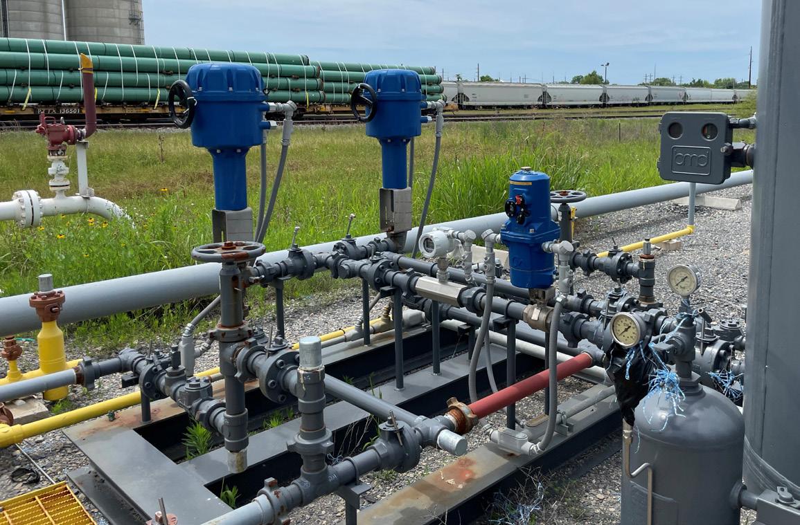
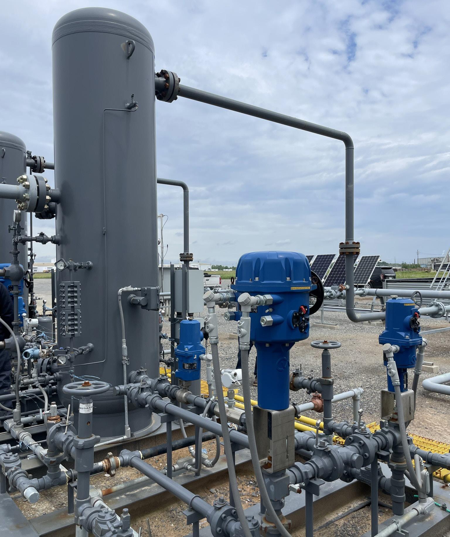
Chris Hardy, Rotork, USA, explains how reliable and advanced automation solutions can help operators reduce emissions, improve process efficiencies and increase production output.
ethane is a powerful greenhouse gas that traps heat in the atmosphere. It is the second most abundant human-made greenhouse gas, after carbon dioxide (CO2), and is more than 28 times as potent at trapping heat in the atmosphere over a 100 year period. It has, therefore, become increasingly important for governments and companies internationally to try and reduce their overall methane emissions throughout industrial processes.
The oil and gas industry is responsible for approximately 80 million tpy of methane, representing about 40% of methane emissions from human activity. These emissions can be reduced by over 75% with solutions such as leak detection, repair programmes, and upgrading leaky equipment. Methane abatement in oil and gas is very cost-effective to achieve. Around 40% of methane emissions could be avoided at no net cost.
Automation in upstream oil and gas operations and processes helps reduce emissions while delivering advanced control, lower power consumption, high reliability, and easy field serviceability. An effective method of reducing upstream methane emissions is installing electric actuators over pneumatic ones.

Electric actuators vs pneumatic actuators relative to overall performance
Electric actuators use electricity as their power source instead of well-stream natural gas. Upstream production process control valves have traditionally been operated by pneumatic diaphragm actuators that use the well-stream gas for their motive power, releasing methane every time the valve is stroked. Electric actuators do not vent during operation.
Maintenance requirements for electric actuators are significantly lower than those for pneumatic actuators and control instruments. Rotork electric actuators deliver selfcontained one-piece actuation solutions, which reduces the risk of failure.
Servicing a self-contained electric actuator vs a pneumatic solution with multiple parts and systems also results in cost savings and increased operational efficiency.
These electric actuators, feature userfriendly interfaces and software tools that


simplify the commissioning process, making them a solution for valve applications in the oil and gas industry.
There are significant advantages to electric actuator technologies vs pneumatic. Pneumatic actuators consist of multiple parts, not just an actuator, which can all suffer from air quality fluctuations, temperature variations, and other environmental factors.
Electric actuators are less susceptible to these influences. They are more energy efficient as they only consume electricity when in operation. In contrast, pneumatic actuators and controls require a constant supply of either motive pipeline gas or locally produced compressed air.
Many electric actuators are available with fail-to-position options that automatically return valves to a predetermined position in case of power loss or emergencies, which enhances safety and prevents potential damage to equipment.
They feature advanced diagnostics, allowing remote monitoring of condition, performance, and potential issues. This proactive approach allows early identification and resolution of problems, preventing unexpected failures and associated downtime.
It is vital for actuators and controllers to provide superior performance and reliability. Intelligent flow control solutions deliver:
Ì Advanced control: actuators can achieve all the necessary torques and thrusts, as well as operate at required speeds for choke valves and process control valves in upstream oil and gas applications. Additionally, they provide the highest resolution output and a modulating duty for precise pressure and flow rate control.
Ì High reliability: designed for reliable and repeatable performance in the dynamic and tough environments of remote oil and gas well sites, actuators are built on selfprotection technology, which guards the unit’s integrity and operating performance by continuously monitoring temperature, torque and voltage, thereby ensuring a longer product lifespan.
Ì Low power consumption: whether to optimise in-field solar power infrastructure in remote locations or effectively manage an escalatory environment of higher-priced available grid power, actuation solutions are energy efficient and consume low levels of electric power.
Ì Field serviceability: in-field interventions such as commissioning and recalibration procedures should be fast and seamless, whether conducted remotely, in control rooms, or through direct physical interaction with the actuator. Actuation solutions provide the most user-friendly experience for upstream oil and gas operators.
Ì Electric actuators are well-suited for upstream applications in the oil and gas industry, such as production trees, processing, gas metering, LACT skids, gas lift systems, and saltwater disposal systems.

Read more at p.19
The production tree (or Christmas tree) is an assembly of valves, spools and fittings that regulate the flow of oil or gas from a well.
In case of overpressure, a surface safety valve (SSV) is a fail-safe/shutdown valve installed at the upper wellbore for emergency shutdown to protect the production tunings. To control the flow of well fluids being produced and to regulate the downstream pressure in the flowlines, a production choke valve is used.
Specifically designed electric actuators, deliver advanced production choke valve actuation with non-intrusive operation, easy setup, proportional control, high accuracy, and low power 24 VDC power configuration. They are lightweight, compact and resilient, designed for long-life applications in the field.

Rotork Modular Electro-Hydraulic Solution combines the simplicity of electrical operation with the high torque/thrust and fail-safe fast-action capabilities of hydraulic high-pressure control for both rotary and linear valve actuation for fail-safe operation of the SSV valve.
Pneumatic diaphragm actuators have traditionally actuated upstream production process control valves. These mostly use well-stream process gas as their power medium and release methane whenever the valve is stroked.
To reduce methane emissions, many operators have replaced well-stream process gas with compressed air by deploying air compressor units at production sites.
An advanced, energy-efficient solution, are suitable for dump valves and back-pressure control valves that are common across upstream production processing applications. They not only help in achieving net zero emissions with a solar-powered 24 VDC supply option but also help reduce the overall life cycle costs compared to the instrument air actuator alternative.
Natural gas production metering and lease automatic custody transfer (LACT) for oil production metering represent a commonly accepted pivot between upstream operations and midstream gathering infrastructure.
Pipelines and valves are usually larger than those across the upstream production processing infrastructure and require higher torque/thrust ranges for valve actuation.
Multiple flow control systems operate together on a custody transfer metering skid to ensure low measurement uncertainty and high metering accuracy. Flow control on metering skids must be highly accurate, reliable and always provide safe valve operation.
To enable the automation of large control valves with high-pressure ratings, a high-output actuator, like the CML, can deliver increased linear thrust and stroke length.
CVA (quarter-turn and linear) delivers an accurate and responsive method of automating control valves without the complexity and cost of a pneumatic supply.
For applications that require lower modulating duty, the IQT3M Pro (multi-turn) has a duty cycle of 1800 starts/hour and provides a torque range and speed suited to the requirements of LACT valve actuation.
The gas lift uses high-pressure gas to lift the well fluids. Injecting gas into the tube causes the fluids’ density to reduce, and the bubbles’ ‘scrubbing’ effect on the liquids lowers the bottomhole pressure that flows through it. Due to gas continuously being injected into the production conduit, a reliable, adequate supply of good quality high-pressure lift gas is mandatory. The control valve requires continuous modulation to adjust the flow and pressure of injected gas.
An electric actuator, is designed for a 100% duty cycle and can operate with precision even for continuous modulating applications. It provides accurate and repeatable position control with up to 0.2% accuracy and S9/Class D continuous modulation capability. It is ideal for back-pressure lines in gas compressors and throttling valves on gas lift metering skids to ensure the required injection flow rates and pressures.
Produced water is the largest liquid produced in the oil and gas industry. The water from the well can be between 4 – 5 times the volume of produced gas or oil from the same well. The produced water is trucked or transported to water recycling tanks or saltwater disposal wells via extensive gathering lines. Across the entire produced water gathering, transportation, and disposal infrastructure are many actuated valves that ensure safe, reliable and efficient flow control of produced water.
Most control valves across the produced water infrastructure system need a high degree of controllability to prevent water hammering, while back-pressure control valves need to operate with the necessary high-level frequency and modulation duty to ensure optimal performance of water injection pumps. The CMQ and IQT3M Pro product lines offer adjustable speed, including slow mode for accurate positioning, high accuracy and high-resolution micro-step movement and adjustable torque/thrust protection.
Reliable and advanced automation solutions can help operators reduce emissions, improve process efficiencies and increase production output. Electrification of valve actuation will help reduce emissions from oil and gas operations. Selecting smart, low-power solutions that are perfectly suited for upstream oil and gas processes will help operators achieve emission reduction goals.


preventive maintenance, and safety in upstream oil and gas operations.
As energy consumption grows annually by more than 2%, society seeks responses to improve well-being, with the environmental aspect playing an increasingly significant role. The solution to this balance of addressing growing energy demand and demonstrating societal responsibility lies in emerging technologies, which enable clean energy sources, sustainable mobility solutions, and improved operational efficiency in the oil and gas sector, whose contribution to the energy ecosystem is absolutely essential. Enhancing operational efficiency means, among other things, maintaining productivity without emitting pollutants that contribute to poor air quality and global warming, therefore implying environmental regulation compliance while simultaneously reducing operational costs and increasing safety.
The sensorisation of assets enables operations to be optimised with minimal human intervention, or even fully autonomously. Operators can trust these sensors to anticipate component failures and take preventive corrective actions, as well as to detect early signs of gas leaks, fire outbreaks, or vandalism.
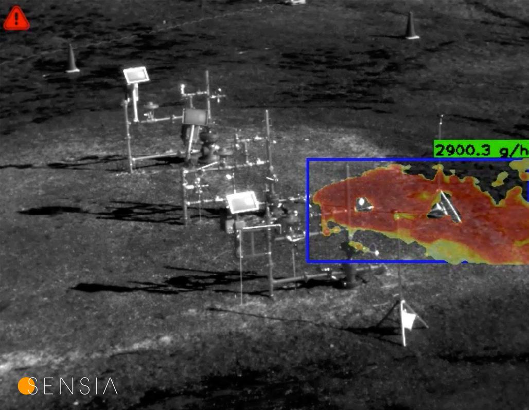
One of the most essential sensing technologies providing the highest level of multi-response capability is intelligent infrared (IR) imaging. Until recently, IR imaging has added significant value to industrial operations by enabling the remote detection of hot spots, gas leaks, and more, but under human supervision. However, advancements in microprocessor computational power and the breakthrough of artificial intelligence (AI) have now made it possible to automate real-time detection in IR cameras.
Smart IR imaging systems, as seen in Figure 1, are already transforming industrial operations with a particular added value in oil and gas operations through methane emissions monitoring at both onshore well sites and offshore platforms around the world. With the integration of AI-powered leak detection and quantification (LDAQ) algorithms to optical gas imaging (OGI) cameras, smart, IR continuous monitoring systems are helping operators meet critical methane emissions reporting under the Oil and Gas Methane Partnership (OGMP) 2.0 framework and regulation from the European Union and the United States while boosting health, safety and environment (HSE) standards. This gamechanging solution for continuous monitoring in upstream oil and gas is already playing a pivotal role in real-world projects, such as measuring flare combustion efficiency and gas leak monitoring at wells in the Permian Basin and autonomous methane emissions monitoring on sustainable platforms in the North Sea and platforms off the coast of Nigeria. This article will explore how smart IR monitoring systems are redefining methane emissions detection and quantification, the role the technology plays in compliance with international regulatory requirements for methane, and how it supports ongoing global efforts toward safer, more sustainable, and more efficient oil and gas production.
Recognising the implied urgency due to increasingly worrying climate reports, regulatory bodies and climate initiatives around the world have increased the pressure on the oil and gas industry to monitor and mitigate methane emissions. This is where advanced technologies like smart continuous infrared monitoring systems come into play, offering precise and reliable solutions that help operators not only identify and manage methane leaks but also comply with increasingly stringent regulations.
One of the key frameworks that smart infrared monitoring systems address is the OGMP 2.0 (Oil and Gas Methane Partnership 2.0) initiative, launched by the United Nations Environment Programme (UNEP). The OGMP 2.0 member framework sets a benchmark for methane emissions reporting for its signees, requiring operators to provide source and site-level quantitative methane emissions data at the highest reporting level. This reporting system is rigorous, given that it requires operators to provide direct quantitative measurements and reconciliation of site-level versus source-level data. Under OGMP 2.0, operators are expected to report methane emissions from five key source categories: equipment leaks, venting, flaring, incomplete combustion, and pneumatic devices, among others. Moreover, upstream operators must also collect this data from both onshore and offshore sites, with an emphasis on reducing methane emissions to meet the broader goals of the Paris Agreement.
Beyond the OGMP 2.0 framework, operators in the oil and gas sector must also contend with a rapidly evolving landscape of national and international methane regulations, particularly in the EU and the Americas. In Europe, the European Commission has rolled out EU Regulation 2024/1787

aimed at significantly reducing methane emissions from the energy sector, requiring quantitative measurements of all aspects of oil and gas operations and will eventually be extended to all oil and gas imports into the EU. Similarly, in the US, methane emissions from the oil and gas sector are under scrutiny. The Environmental Protection Agency (EPA) has introduced sweeping methane regulations OOOOa, OOOOb, and OOOOc requiring operators to use advanced technologies for leak detection and quantification and flare combustion efficiency, including OGI cameras.
Smart IR imaging technology, with its advanced methane leak detection and quantification capabilities, is ideally suited to help operators comply with both EU, US, and other national emissions regulations and paint a more truthful picture of operator emissions. Its ability to detect and quantify methane emissions in real-time not only ensures compliance but also helps operators mitigate leaks before they become environmental, safety, or regulatory nightmares rather than awaiting periodic inspections.
The basics of smart IR imaging technology and the role of AI
Smart IR imaging systems require state-of-the-art IR cameras supported by AI-powered processing software and analytics, forming a complete, autonomous solution very few companies offer and even fewer have mastered. As is widely known, IR imaging is used in a wide variety of applications from surveillance to gas detection. A multitude of gases normally

invisible to the naked eye have an absorption presence in the IR spectrum, including most hydrocarbons like methane. There are clearly defined IR adsorption levels of methane (CH4) and other hydrocarbons in mid-wave (MWIR) and long-wave (LWIR), although SWIR is so similar to visible light that it requires sunlight to perform detection of only very big leaks whereas cameras based in other regions of the IR spectrum can operate day and night detecting smaller leaks as well. OGI cameras are equipped with spectrally tuned IR detectors to see just in narrow IR bands. To summarise, these detectors reveal in infrared what is invisible for the naked eye like the temperature of the components, invisible flames and gases, but that is only the beginning.
AI analytics and the proper electronic components are responsible for the last steps in smart IR imaging, the actual detection confirmation of gas, flame, temperature, people, flares, pilot flames etc. which is then followed by alarm generation and communication to the distributed control system (DCS), report creation, and other preset actions. AI utilised in smart infrared monitoring systems is trained with various laws of physics, hundreds of real scenarios of different detection targets, resulting in faster, more accurate and reliable performance without the need of human oversight. In addition to real-time gas detection and quantification at site and component levels, intelligent infrared imaging technology can perform flame detection, intelligent thermography, surveillance, flare efficiency monitoring, adding even more safety and environmental benefits for operators. Figure 2 and Figure 3 show detection and gas leak quantification examples from the field.
Incomplete combustion of flares is labelled by regulatory bodies and environmental groups as another main source of methane emissions. Smart infrared imaging is able to address new minimum flare efficiency requirements by not only visualising unburned hydrocarbons such as methane, but also simultaneously comparing the unburned input gases to the resulting carbon dioxide output. As carbon dioxide and hydrocarbons are both present in the infrared spectrum but at different wavelengths, a bi-spectral camera such as the system shown in Figure 4, is needed to assess the gases at different infrared bands. As seen in Figure 5, operators are granted realtime reports of flare conditions and efficiency changes in terms of destruction and removal efficiency or combustion efficiency according to operator needs, drastically improving measurement accuracy and frequency to meet regulatory requirements.
Upstream sites, onshore and offshore alike, continue to adopt and consider this new approach to methane emissions monitoring and quantification. From new sustainable platforms in the North Sea, other platforms off the Nigerian coast and in Southeast Asia, to well sites in the Permian Basin, and more regions of the globe, operators from oil and gas majors are acting on the advantages of smart infrared monitoring systems for methane emissions measurements, surveillance, and preventive maintenance. In one offshore case, an intelligent infrared system was implemented in one specific compressor room in an offshore platform. The system offered a real-time view of methane emissions, facilitating quick response to any anomalies with visual confirmation. It resulted in the complete mitigation of leaks, upgrading the safety and environmental standards to the


next level. In addition, the intelligent thermography functionality spotted components that were operating above maximum temperature thresholds and created alerts to anticipate a component failure.
On another offshore case, an explosion-proof camera and panand-tilt system for autonomous emissions monitoring of multiple areas was installed on a sustainable platform running completely off wind power in the North Sea. The system continues to perform at the highest caliber even in the harsh offshore environment, where traditional methane detection methods can be difficult to deploy and maintain. The technology’s ability to provide realtime, site-level emissions data is essential for both regulatory compliance and operational efficiency, allowing the operators to further minimise its environmental impact while maximising production on a sustainable platform.
In the Permian Basin, well site operators from several majors are opting for a semi-continuous monitoring system mounted


on a mast and trailer that autonomously monitors a large area of well sites for a pre-determined period ranging from several weeks to several months around the clock. The system autonomously performs tours of key well sites, spotting, quantifying and recording any leaks it finds. The lower required investment of well operators for this approach and added flexibility due to the ability to transport the system to different locations after a campaign made it even more ideal. Although this is a semi-permanent approach and isn’t considered fully continuous monitoring, the length of the campaigns and 24 operation allows operators to conduct leak detection and quantification campaigns as the conditions change at the site, a major difference from alternative solutions.
As most flaring in the oil and gas sector takes place in upstream sites, flare efficiency monitoring solutions using smart infrared are of the upmost interest. Even capable of observing multiple flares from the ground or a mast with the correct supporting equipment, operators program tours and presets to monitor flares around the clock completely unattended. The continuous readings over long periods of time offer a plethora of valuable information regarding efficiency that before simply were assumed or estimated.
The oil and gas industry is at a crossroads, facing increased pressure to reduce its environmental footprint while maintaining operational efficiency with demand projected to continue increasing. Technologies like smart infrared imaging with AI-powered software and analytics with cutting-edge IR cameras are helping operators navigate regulatory and safety challenges by providing the tools they need to monitor, report and reduce methane emissions and accidents in real-time. As methane regulations continue to tighten, both at the international and national levels, the importance of reliable, precise methane emissions monitoring will only increase. The versatility of intelligent IR systems provides real-time data at both source and site levels and makes it an indispensable tool for any operator looking to stay ahead of the regulatory curve as well as boost operational efficiency and safety. Moreover, as more operators adopt advanced technologies like smart infrared monitoring systems, society as a whole will move closer to achieving its sustainability and digitalisation goals, reducing contributions to global methane emissions, mitigating the impacts of climate change while also overcoming health, safety and environment challenges.
Smart infrared technology for continuous methane emissions monitoring, preventive maintenance, and personnel surveillance represents a significant step forward in digitalisation for the upstream oil and gas sector. By providing real-time, AI-driven insights into methane leaks over longer periods of time compared to intermittent technologies, smart infrared helps operators meet the stringent requirements of frameworks like OGMP 2.0 while also complying with new EU and US methane regulations. Successful deployments and increased adoption at well sites and platforms of oil and gas majors in Europe, the Americas, Africa and Asia highlights its potential to enhance methane emissions monitoring in terms of fugitive emissions and flare efficiency. Smart infrared truly is a game-changer for emissions monitoring, preventive maintenance and safety in upstream oil and gas.
Volker Peters (Germany) and Daniel Bell (USA), Baker Hughes, describe the challenge of HFTO, and how a new torsional dampener tool can suppress oscillations and improve operation.

he ability to drill longer horizontal wells and laterals improves well economics but pushes the technical limits of bottomhole assemblies (BHAs) in complex well designs. A key challenge introduced is high-frequency torsional oscillation (HFTO): self-excited vibration resulting from bit/rock interaction that can cause premature damage to drilling tools and components, leading to increased capital costs and unplanned downtime. Engineers have been working for decades to understand and resolve HFTO, but until recently, tools designed to mitigate vibration have been only marginally successful.

Figure 1. Depth based averaged surface and downhole data. (Image courtesy of Baker Hughes). Graphic is from SPE-217677-MS ‘Effectiveness of HFTO-Dampener Assembly Proven by Extensive Case Study in Permian Basin’ presented at the IADC/SPE International Drilling Conference and Exhibition, Galveston, Texas, March 2024, https://doi.org/10.2118/217677-MS

Figure 2. Depth based averaged surface and downhole data. (Image courtesy of Baker Hughes). Garphic is from SPE-217677-MS ‘Effectiveness of HFTO-Dampener Assembly Proven by Extensive Case Study in Permian Basin’ presented at the IADC/SPE International Drilling Conference and Exhibition, Galveston, Texas, March 2024, https://doi.org/10.2118/217677-MS
HFTO and traditional solutions
HFTO typically occurs in the BHA, generating dynamic oscillations in the range of ~50 Hz to ~400 Hz. The vibration motion-induced twist in the drill string causes dynamic torque, which increases the load on drill string components. One of the unfavourable consequences is premature fatigue damage of tools and components, resulting in slower drilling for mitigation and more nonproductive time (NPT). Another is damage to sensitive components – such as sensors, electronics and even connectors and electrical wires –caused by acceleration.
Many tools that claim to address HFTO have had limited success because they focus exclusively on managing bit induced stick-slip, which is caused by the bit-rock cutting interaction and results in drill bit rotation alternating between periods of slowing down and suddenly accelerating. Stick-slip tools, placed above the BHA, reduce stick-slip vibration between axial and torsional degree of freedom via a mechanical coupling (a spline connection or wire ropes) to initiate axial motion when torque changes occur. The tools themselves mitigate vibration by reducing the depth of cut through reduction of weight on bit (WOB).
If HFTO is not mitigated properly, WOB and/or bit rpm has to be reduced to limit vibrations to acceptable levels, which in turn reduces rate of penetration (ROP). Costly reductions in ROP are impediments for achieving optimal field economics, but an equally significant problem with such axial-torsional coupling tools is that they focus primarily on stick-slip, and only occasionally reduce levels of HFTO. The result is that, although these tools have proven marginally successful in reducing HFTO, in instances where downhole conditions demand higher dampening, the tools are unable to resolve it.
The shortcomings of traditional tools that address HFTO led Baker Hughes to invest in research to better understand what happens downhole to incite excessive vibration and how models could be developed to better comprehend it. Employing the results of this research, engineers designed a torsional vibration dampener tool that is purpose built to suppress all modes and instances of HFTO for all drilling parameters employing a novel design with no load bearing components that have differential motion, unlike the axial - torsional coupling.
The unique tool is one rigid piece that is affixed to the BHA. It has no parts requiring grease-filled compartments that need to be protected with dynamic seals like some stick/ slip solutions. This design eliminates reliability concerns because there are no moving mechanical parts, bearing drilling load. Torque and drilling nodes are fed through rigidly connected collars.
The function principle is based on an internal inertia mass that can freely rotate with respect to the centre of the drilling system but is connected to the BHA by a dissipative force. When no torsional vibrations are present, the inertia mass rotates together with the BHA. In the presence of HFTO, inertia mass resists the motion of the vibration. Designed and built to suppress HFTO holistically, this tool creates sufficient dampening in a frequency band of 50 – 500 Hz.
The dampening tool is most commonly run on top of the BHA, although in cases where a downhole motor is used, the dampener is placed below the motor. In either configuration, the tool is handled like a regular drilling tool, with no need for special setups or electrical configurations. Due to its design and placement on the BHA, the dampener does not compromise formation evaluation sensor positioning or the steerability of the rotary steerable system.

Figure 3. This chart shows the amount of HFTO time per circulating time for runs using the two competitor vibration mitigation tools and the GuardVibe HFTO tool. (Image courtesy of Baker Hughes). Graphic is from SPE-217677-MS “Effectiveness of HFTODampener Assembly Proven by Extensive Case Study in Permian Basin” presented at the IADC/SPE International Drilling Conference and Exhibition, Galveston, Texas, March 2024. https://doi.org/10.2118/217677-MS

This unique technology enables dampening of high-frequency torsional oscillations for the entire BHA, which provides several benefits to the drilling operation. It extends the operating life of the BHA, improves stability, efficiency, and directional control while drilling through transitions, achieves higher ROPs by not holding back ROP because of vibration, and extends run life downhole. It also expands the drilling envelope by allowing harder formations to be drilled without reducing the drilling parameters.
Figure 4. Mean Time between Failure (MTBF) of the BHA. Graphic is from SPE-217677MS ‘Effectiveness of HFTO-Dampener Assembly Proven by Extensive Case Study in Permian Basin’ presented at the IADC/SPE International Drilling Conference and Exhibition, Galveston, Texas, March 2024, https://doi.org/10.2118/217677-MS
To ensure vibration dampening is sufficient, specifications for the entire BHA string that will be used on the drilling job are entered into a software model, and a piece of code adapted for the software optimises the placement and the performance of the dampening devices. The software tries different numbers of devices and all possible configurations and selects one in which the efficiency of the dampeners is maximised for all anticipated scenarios. Tools are positioned according to dampening demand, and engineers can tailor parameters and performance outputs as HTFO levels increase and can dampen them appropriately, so they are not damaging or obstructive. This level of performance is not achievable with other vibration mitigation tools.
All Baker Hughes dampener tools are laboratory tested to extremes for durability and reliability using cyclic bending, shock and vibration, temperature, pressure testing methods. Functional testing of dampening performance is executed with scaled lab samples using multiple sensor elements.
The entire BHA, with the torsional vibration dampener attached at the top of the drilling BHA (but below the
mud motor if one is used) is preconfigured for the job. The appropriate vibration dampening configuration is delivered to the rig site as one piece ready to install. The presence of the tool on the BHA does not restrict drilling in any way. The only noticeable difference between a BHA without the tool and a BHA with the tool is HFTO suppression.
Field tests over the course of more than 350 drilling runs, primarily in harsh environment conditions in the Midland and Delaware sub-basins in the Permian Basin – where extended reach drilling is common – delivered 98% of the circulation time free of HTFO.
Results from two of these field implementations illustrate how the torsional vibration dampening technology performed in real-world conditions in comparison to other HTFO management tools on the market.
In the first application, the Baker Hughes GuardVibeTM high-frequency torsional oscillation dampener technology was employed in the first instance in the curve and drilled the first part of the lateral section (Figure 1). The BHA was tripped because of bit wear and low ROP, and in a second run, the proprietary HFTO tool was used again in the lateral section. In both runs, the BHA experienced
nearly no HFTO and maintained an ROP between 300 ft/hr and 120 ft/hour. In the second run, there were slightly increased levels of tangential acceleration between 13 000 ft and 14 000 ft, indicating that the GuardVibe HFTO tool was dissipating energy to prevent HFTO from rising to its plateau amplitude.
In Figure 1, the green tracks represent data acquired from runs with the GuardVibe HFTO tool. The yellow tracks represent data from a run with a commercially available stick-slip tool. Tangential acceleration (HFTO), represented in the second track from above, is mitigated and suppressed using the GuardVibe HFTO tool. Conversely, HFTO is largely present using the commercially available stick-slip tool. For reference, ROP, WOB and rock formation properties are displayed as well, in the three bottom tracks.
After a motor failure at the end of the second run, a different vibration mitigation tool was deployed (Competitor 2). The results using this traditional tool were suboptimal, with high HFTO levels throughout the run, which negatively impacted ROP. Using the traditional tool also required WOB to be reduced to mitigate vibration. The formation values in this run were similar to those where the GuardVibe HFTO tool had been deployed, indicating that downhole conditions like these are likely to produce high HFTO levels, which can be successfully suppressed using the proprietary technology.
In a second application, the GuardVibe HFTO tool was benchmarked against vibration mitigation tools from two other vendors (Figure 2). A load sensor mounted on the BHA measured dynamic torque, while accelerometers positioned in two areas – one next to the load sensor and the other farther up the BHA – measured tangential acceleration amplitude and dominant frequencies.
The first run was drilled with the tool from Competitor 1, the second run was drilled with the tool from Competitor 2. The third and fourth runs were drilled with the GuardVibe HFTO tool. All runs were conducted in the lateral section.
In Figure 2, the blue and yellow tracks represent data from separate runs using two commercially available stick-slip tools. The green track represents data acquired from runs with the GuardVibe HFTO tool. Tangential acceleration (HFTO), represented in the second track is mitigated and suppressed using the GuardVibe HFTO tool, but HFTO is largely present using the two commercially available stick-slip tools. For reference, ROP, WOB and rock formation properties also are displayed in the three bottom tracks.
The BHAs for both Competitor 1 and Competitor 2 experienced high HFTO-related loads, with different levels/ plateaus of tangential acceleration measured. This was caused by different dominant HFTO frequencies between 200 Hz and 300 Hz. The GuardVibe HFTO tool, on the other hand, mitigated HFTO to amplitudes close to zero. Even in formations that were tougher to drill, represented for example by the section between 14 000 and 16 000 ft, indicating a harder rock formation, where WOB was set to high levels but resulted in comparably low ROP, the GuardVibe HFTO tool eliminated HFTO altogether.
To carry out benchmarking, 44 runs were drilled using the proprietary tool, 113 runs were drilled with
the vibration mitigation tool from Competitor 1, and 39 runs were drilled with the vibration mitigation tool from Competitor 2 (Figure 3 and Figure 4).
In this case, the vibration mitigation tools were placed between the mud motor and the wired part of the BHA. All the runs were carried out in comparable target formations, with similar PDC bits and BHAs.
The duration of HFTO in hours per 1000 hr circulating time for the vibration mitigation tools is shown in Figure 3. The GuardVibe HFTO tool experiences close to zero time with HFTO. The runs with Competitor 1 experienced an average of more than 26 hours/1000 hours drilled, and the runs with Competitor 2 experienced an average of more than 138 hours/1000 hours drilled.
It is important to recognise that the reliability of this tool and the reliability of the other BHA components are all important for project economics. In this drilling programme, the runs using the GuardVibe HFTO tool had a significantly higher reliability with Mean Time Between Failures (MTBF) at least 100 % higher than Competitor 2 and about 50 % higher than Competitor 1 for the complete BHA, including the dampener tool (Figure 4, MTBF).
MTBF is a key performance indicator of NPT and represents cost drivers in drilling operations. Figure 4 shows that mitigation of HFTO exposure directly correlates to reliability measures of the drilling BHA. The runs using the GuardVibe HFTO tool experienced close to zero HFTO (eg ~twice MTBF achieved using the tool from Competitor 2, which had the highest percentage of HFTO). The intrinsic, high reliability of the dampener tool design, along with its ability to mitigate HFTO, are key to the excellent overall performance in the application.
Thus far, nearly all of the tool installations have been in the Permian Basin using 4.75 in. tools, which creates a compelling case for employing the technology elsewhere. Already, the technology is being used extensively in drilling applications in Argentina, and there are opportunities in the Eastern Hemisphere – in drilling programmes in areas like China and Saudi Arabia where HFTO is a challenge – where this technology could significantly improve performance.
Designed to be agnostic, this tool can be used in all rotary steerable drilling applications. Recent field deployments in Saudi Arabia have proven effective in conjunction with complex MWD/LWD (Triple Combo) drilling BHAs. Unlike the deployments in the Permian Basin, the drilling runs carried out in Saudi Arabia were performed using a rotary from surface, without a drilling motor. This is a significant achievement because in Saudi Arabia, where drilling with advanced LWD tools is common and drilling programmes are non-motor assisted, traditional HFTO solutions have been either inefficient (stick-slip mitigation tools) or have displayed other deficiencies, like reducing torque throughput or increasing sensor offset.
As more data is gathered from more drilling environments, it will be possible to tailor solutions for a broader range of applications and in time, develop additional tool sizes to enable more efficient drilling programmes in every corner of the world.
Mariano Guerrico, Global Technology Manager, Tracerco, describes how cutting-edge technology has transformed flow control and monitoring, showcasing a case study from the Santos basin offshore Brazil.

nsuring consistent, efficient production in offshore oil and gas operations has never been more challenging. As reservoirs mature and fields become increasingly complex, operators must contend with issues such as slugging, hydrate formation, and sand production, all of which can compromise flow assurance and pipeline integrity.
Traditional measurement and inspection methods are often intrusive and disruptive, and don’t provide the real-time insights needed to optimise production and maintain regulatory compliance. Non-intrusive, real-time diagnostics help operators maximise uptime, reduce costs and enhance safety.
Overcoming flow assurance challenges through nonintrusive monitoring
Flow assurance issues pose a constant risk to production efficiency. Severe slugging can cause unstable production rates and increase wear on equipment, while hydrate formation can lead to blockages that require costly shutdowns to

resolve. Sand production further complicates operations, risking erosion damage and compromising pipeline integrity.
Historically, identifying and diagnosing such problems relied heavily on intrusive monitoring tools or required halting production to conduct inspections – both of which not only impact operational efficiency, but can also expose personnel to greater safety risks during physical intervention.
Operators today face ever-tighter regulatory scrutiny, making continuous, accurate monitoring essential not only for production optimisation, but also for environmental and safety compliance.
A recent collaboration with Brava Energia in the Atlanta Field, located in the northern Santos Basin approximately 185 km southeast of Rio de Janeiro, perfectly illustrates the benefits of Tracerco’s approach. The field holds an estimated 1.8 billion bbls of original oil in place (OOIP). Discovered in 2001, this ultradeepwater field sits beneath 800 m of overburden at a water depth of 1550 m. It is operated by a consortium led by Brava Energia (80%) and Westlawn (20%).
This case study showcases the evolution of oil and water contribution by using Tracerco tracers and also Autonomous Inflow Control Devices (AICD). Atlanta Field is a post-salt heavy oilfield. Several challenges of the field needed to be considered: unconsolidated sandstone, heavy/viscous oil (14˚ API, 228 cP), high water cut risks, and no injection wells - making precise reservoir management critical.
The primary reservoir, located in the Eocene interval, comprises high-quality sandstone with net-to-gross ratios between 82 - 94%, porosity averaging 36%, and permeabilities ranging from 4 to 6 Darcy. However, despite its favourable rock properties, the oil is heavy (14˚ API), viscous (228 cP), and acidic (TAN = 10 mg KOH/g). The reservoir benefits from a strong bottom aquifer, eliminating the need for injection support.
To manage technical and economic risks, the field development was phased in two parts:
Ì Early production system (EPS) from 2018 to 2024, with four horizontal producers and a 30 000 bpd capacity FPSO. Ì Full field development (FFD) to expand to 12 producers connected to a new FPSO (ATLANTA FPSO) capable of handling 50 000 bpd.
To optimise production and mitigate water breakthrough risks, Tracerco deployed oil and water polymer tracers across multiple horizontal wells. These were paired with AICDs (wells ATL-4HB and ATL-5H) and Open Hole Horizontal Gravel Pack completions. The goal was to assess oil inflow distribution along the wellbore, early water ingress, and AICD effectiveness
in moderating flow and extending well performance.
The EPS was projected to de-risk reservoir uncertainties such as: well productivity, inflow performance along the horizontal section of the well, and aquifer support.
Mariano Guerrico, Global Technology Manager at Tracerco, said: “Understanding these unknowns was essential to define the drainage strategy and Full Field Development (FFD) design. To improve economic results, long Open Hole Horizontal Gravel Pack wells were required. After the completion of the first two wells, the decision was made to integrate Autonomous Inflow Control Devices (AICDs) into the screens. To evaluate oil inflow distribution, water breakthrough, and AICD performance along the horizontal well sections, oil and water tracers were strategically placed at different positions along the screens.
“Tracer production data, combined with EPS dynamic data such as PDG pressures, build-up tests, water cut trends, and Gasto-oil Ratio (GOR) behaviour, delivered a new level of insight into aquifer drive dynamics, water production, and well productivity index performance. This robust dataset was instrumental in shaping the updated FFD plan for Brava Energia at the Atlanta Field.
“The successful application of tracers played a vital role in mitigating reservoir risk and optimising the development of this heavy oil deepwater asset with a significant underlying aquifer. With encouraging first results from the Atlanta FPSO’s full production phase, the Early Production System project stands as a clear success that de-risked and accelerated the path to full-field execution.”
Tracers were installed in four key EPS wells and high-frequency oil sampling along with lab GC-MS analysis were used to track flow from individual zones. Tracer results were used to refine the Full Field Development (FFD) design, including artificial lift (seabed multiphase pumps). To understand the behaviour of each sand zone identified in the Atlanta reservoir, the tracers were strategically positioned considering at least one oil and water tracer per each sand zone. Also, at least one oil and water tracer was positioned in the well heel and toe.
Tracer results and flow behaviour are presented for wells ATL-2HP, 3H, 4HB, and 5H.
ATL-2HP
Ì Oil flowed from all tracer points.
Ì Initial flow favoured toe region (3332 - 3462 m).
Ì After shut-in, flow contributions shifted, and production became more evenly distributed.
Ì Water flow also initiated from toe zone, declining post shut-in.
ATL-3H
Ì Oil flowed from all sections.
Ì Early flows were toe-dominant, later shifting to the heel.
Ì This dynamic inflow shift indicates evolving pressure and saturation patterns over time.
ATL-4HB
Ì Heel (2819 - 2996 m) contributed most of the oil production (63%).
Ì Water ingress was highest at tracer T-931 (3458 m), activating AICDs and limiting flow there.
Ì Adjacent oil tracer T-701 became undetectable, confirming AICD effectiveness in high-water zones.
Ì Heel-mid zones dominated oil production; toe flow declined in later samples.
Ì Water entry was highest in the heel; toe water increased over time.
Ì This evolution reflected the balancing effect of AICDs in response to rising water saturation.
This strategy proved highly beneficial - equalised inflow and water breakthrough delay was observed in the wells equipped with AICDs and tracers. Well ATL-4HB, located at the reservoir’s structurally highest point, showed the slowest water production increase and strongest AICD effect. The non-intrusive insight into fluid dynamics helped optimise completion design and de-risk the FFD strategy - directly improving productivity and reducing OPEX.
In order to enable the inflow tracer analysis, oil samples were collected after the startup of the wells or expected shutdowns usually for a 48 hour high frequency sampling campaigns. For the water tracer analyses, when absent of free water, the oil samples were submitted to the procedure of extraction using mainly proper demulsifiers. Then, the oil and water samples could be analysed for chemical tracers at the Tracerco laboratory in Rio de Janeiro by gas chromatography with mass spectrometry (GC-MS).
The project delivered a clear, quantifiable impact: the EPS phase alone yielded 30.7 million bbls of oil and informed a refined full field development plan involving 12 producers. By providing real-time, zone-specific inflow and water data without the need for intervention, Tracerco helped reduce operational uncertainty and supported more confident, data-driven decision-making.
Overall, the Atlanta EPS phase achieved its main objective: de-risking the reservoir and informing the FFD strategy. Key takeaways include:
Ì AICDs significantly enhance water control and flow uniformity.
Ì Tracer data validated inflow behaviour and confirmed well productivity trends.
Ì Multiphase seabed pumps outperformed in-well ESPs in terms of reliability and economic efficiency.
Ì The FFD wells maintain strong productivity with no observed design-related performance issues.
Future tracer data from ATL-6H and 7H will further refine the understanding of Atlanta’s reservoir performance, supporting ongoing production optimisation and field longevity.
Beyond specific case studies, the broader advantages of Tracerco’s non-intrusive flow monitoring solutions are clear. Operators benefit from faster diagnostics, allowing for immediate decisionmaking and remediation before problems escalate. Production efficiency is significantly enhanced by optimising flow rates and separation processes without the need for interruption. Cost savings are achieved not only by reducing downtime but also by limiting the frequency and cost of maintenance interventions.


sampling period during the clean out.
As offshore fields become more complex and production systems more demanding, the role of advanced, non-intrusive monitoring will only continue to grow. By offering real-time, accurate, and safe solutions for flow monitoring and integrity assurance, Tracerco is helping operators in North America, the UK, Europe, and South America stay ahead of operational challenges, optimising production while safeguarding both people and assets.

Kostas Sklikas, MBA, Global Product Marketing Manager, Brooks Instrument, summarises the roles and advantages of variable area flowmeters in offshore drilling.
Offshore oil platforms face some of the most demanding environmental and operating conditions. There is constant exposure to extreme temperature ranges, saltwater, severe storms and corrosive spray. These rigs typically operate roundthe-clock, reaching thousands of feet down into the water and then drilling through multiple geologic layers for well exploration and production.
Under these hazardous and challenging conditions, offshore rig operators need rugged and reliable instruments to help measure, monitor and safely control all their complex systems. Accurate flow measurement of the delivery of drilling fluid at controlled high pressures is one of the most critical drilling rig system requirements. Variable area (VA) flowmeters offer that performance. They are proven, reliable, well-engineered flow measurement devices used in a wide range of oilfield and offshore platform applications.
Drilling fluid, also called mud, is a complex, often proprietary chemical mixture that performs multiple functions when drilling

a well. It is typically a heavy, viscous mixture, with many types of fluids used on a day-to-day basis. Some are water-based, some are oil-based or synthetics, and all can incorporate a range of additives, such as lubricants, shale inhibitors and fluid loss materials.
Different types or combinations of fluids are used as substrate conditions change. Fluid management involves a complex delivery and recirculation system that performs several functions during drilling. These include:
Ì Cleaning the hole by transporting drilled cuttings to the surface, where they are removed from the fluid before it gets recirculated down the bore hole.
Ì Supporting and stabilising the walls of the wellbore until casing can be set and cemented into the wellbore.
Ì Preventing or minimising damage to the producing formation.
Ì Cooling and lubricating the drill string and bit.
Ì Transmitting hydraulic horsepower to the bit.
Ì Providing rig operators with information about the producing formation through cuttings analysis, logging-while-drilling data and wireline logs.
VA flowmeters offer rugged reliability and accuracy
While there is a range of options for monitoring drilling mud flow, one of the most effective and reliable tools is the metal tube VA flowmeter. VA flowmeters are extremely versatile and widely used in a range of industrial applications, particularly in chemical plants, oil refineries and offshore rigs, to measure and control applications involving high fluid flowrates and pressures. The basic technology, first developed over a century ago, provides a simple and reliable means to measure fluid flow.
The main elements of a VA flowmeter include the tube and the float. The tube is fixed vertically, and the fluid is fed from the bottom. The float inside the tube moves in proportion to the rate of fluid flow and the area between the tube wall and the float. When the float moves upward, the area increases while the differential pressure decreases. A stable position is reached when the upward force exerted by the fluid is equal to the weight of the float. This enables measurement of the flowrate by a scale, or a mechanical or magnetic follower connected to the float and driving a meter display external to the tube.
Due to the conditions in offshore drill rig applications, metal tube VA flowmeters are typically specified. They

Figure 1. Variable area flowmeters like the MT3809G from Brooks Instrument are durable and accurate for high-pressure and extreme temperature applications. For offshore applications, well-constructed VA flowmeters typically use 316/316L Dual Certified stainless steel with Alloy 625, Hastelloy C-276 or Titanium GR II.
are suitable for temperatures and pressures common in these environments and are generally manufactured of stainless steel, aluminum or brass. For offshore applications, well-constructed VA flowmeters typically use 316/316L Dual Certified stainless steel with Alloy 625, Hastelloy C-276 or Titanium GR II.
Easy to install, use and maintain, VA meters offer many benefits in flow metering solutions:
Ì No power required – a majority of VA applications are mechanical indicator-only, and therefore no power is needed to measure flow. Costly wiring is not required and the VA meter can be installed in any hazardous area.
Ì Low pressure drop – VA meters can be installed in multiple locations over one process line without significant pressure loss.
Ì Repeatability – VA meters are often used for flow measurement due to high repeatability of measurement.
Ì Cost-efficiency – VA meters are generally lower in initial cost as well as lifetime costs, with little need for maintenance.
Ì Versatility – manual control valves are available, from very small meter sizes to 2 in. line size meters.
Ì Material availability – options are available for different types of metal tubes.
Given these key functional and operational features, many offshore rigs utilise metal tube VA flowmeters to monitor and control drilling fluid flowrates. Devices like the MT3809G VA flowmeter from Brooks Instrument offer key advantages for consistent, repeatable pumping of drill mud under severe process conditions.
They are engineered and manufactured for years of use, with corrosion-resistant and stainless-steel housings that can withstand high pressures up to 885 bar. They are also designed for reliable performance, regardless of the range of drilling fluid mixtures used throughout the drilling process, which can change as conditions change in the producing formation.
Once the mud reaches the drill bit, the mud will cool off and lubricate the bit and efficiently transport the cuttings back to the surface. VA flowmeters can support a range of temperatures, from -198°C/135°F to 420°C/788°F, ideal for the broad span of temperatures encountered on offshore rigs, from the Gulf of Mexico to the North Sea.
When selecting VA flowmeters for use in drilling fluid systems, it is useful to understand several key criteria to determine if the device provides the right performance and control the system requires. These considerations can include:
Application flowrate: knowing an application’s required flowrate is necessary when specifying a VA meter. The goal is to select a VA meter where the normal operating flow is in 60 – 80% of the meter’s range, because a VA meter is more accurate in the upper part of its range. Additionally, the meter must also handle the minimum and maximum flows. The other important component of flowrate is units. If the unit is too small for the meter selected, the flow number can be minuscule or too large.
Fluid density and viscosity: physical characteristics of drilling fluids must be considered when specifying a VA meter. This can be a challenge if an offshore operation is using different fluids at different points in the well-boring process, due to a variety of operational and condition factors unique to that well — conditions that can change as the drill operators analyse data from the drilling cuttings.
Fluid density and viscosity are important because these two values allow engineers to select the right meter size. Performance data is usually collected on different VA meters so that manufacturers know which ones will fit the supplied process conditions (density and viscosity).
Hardened and safe housings: VA flowmeters need to operate reliably for years in harsh environments. In addition, some models are incorporating electronics that need to be kept secure from water contamination. Technology suppliers are responding to these needs with VA flowmeter housings engineered for heavy-duty use where electronics like transmitters, alarms and local operator interface displays must operate in harsher outdoor environments. For example, the Brooks Instrument MT3809G VA flowmeter with an intrinsically safe aluminum housing has an IP66/67 NEMA 4X rating that offers improved corrosion resistance and better performance against water penetration. It has been tested against both power spray down and submersion in up to 3 ft of water without impacting its flow measurement accuracy.
Accuracy: VA meter accuracy is computed using a fullscale accuracy method rather than one of rate accuracy. VA meters are much more accurate in the upper end of a flow range, but more VA meters are used for repeatability of flow measurement. This means, given the same process

conditions, the float will repeat and be at the same scale reading.
Every offshore drill platform has unique environmental and geologic producing conditions that determine the composition of the drilling fluid and the operation of the fluid system. These conditions can affect VA flowmeter selection, including how many meters to incorporate in the system and how their output should be integrated into drilling control operations.
There are advantages to working with an instrumentation provider that has extensive experience with flow measurement and control devices in rugged offshore applications. This includes companies like Brooks Instrument, which can offer a robust global service and support infrastructure if device servicing or calibration is needed, or if replacement flowmeters are needed quickly out in the field.
It’s also important to choose a flowmeter supplier who can provide applicable approvals for your specific hazardous environment and conditions. Brooks Instrument, for example, has a dedicated approvals and certifications resource webpage and a team of experts to help users get the approvals they require.
To be successful and bring producing wells online, offshore drilling rigs need precise and reliable control of their drilling fluid systems. The metal tube VA flowmeter provides rugged, proven performance, as well as simplicity and ease of installation, to help ensure that drilling fluid systems operate with maximum efficiency and accuracy.


anaged pressure drilling (MPD) progressed deepwater operations by delivering a critical safety advantage for drilling the world’s most complex and challenging wells. Now a common practice globally, MPD is advancing novel methods and technologies that will push drilling beyond the conventionally un-drillable — and into the next frontier of subsea exploration.
With safety and efficiency driving performance, drillers can standardise their MPD operations by integrating a singular system onboard their offshore assets to minimise risk. Integrating a riser joint into MPD operations provides a streamlined approach to help drilling contractors simplify processes while easing rig-to-rig transfer of technology and crew expertise.
MPD is an adaptive and advanced drilling solution that has made historically challenging wells feasible. By accurately controlling the annular hydraulic pressure profile throughout the wellbore, MPD provides the dynamic control necessary to drill into difficult reservoirs safely and efficiently, resulting in less nonproductive time (NPT).
MPD is not a singular, standardised process, however. It requires multiple tools and techniques to control pressure while drilling complex formations. Drillers can take a variety of approaches in this closed system to control back pressure and circulating friction, adjust mud density as well as the annular fluid level, and modify fluid rheology among other activities.

In some deepwater pressure reservoirs, such as those found offshore near Brazil, MPD has become a requirement to ensure wellbore pressure is overbalanced and under control. If pressurised mud circulation is too heavy, the formation can crack, or if it’s too light, other issues can occur. Consequently, MPD traditionally adds additional layers of operational complexity with regard to equipment, processes and workflows.
To resolve these application challenges, the Oil States MPD Integrated Riser Joint (IRJ) system enables efficient wellbore pressure control and flow management while also improving the safe handling of gas influx. This combination can significantly reduce the NPT typically encountered with deepwater MPD operations, simplifying deployment and increasing safety.
Unlike legacy equipment, the Oil States IRJ is specifically designed to enhance MPD operational efficiency on-site. With twin retrievable annular seals, the system can remain in place for easy change out between conventional drilling and MPD, simplifying operations through instrumentation integration and NPT. Supplied with the appropriate riser connection and auxiliary line configuration, it seamlessly integrates with a vessel’s existing riser system as it’s compatible with multiple risers and topside equipment from various MPD suppliers. As an advanced automated technology, the IRJ system also gives

Garry Stephen, Vice President, UK and Asia, Oil States, examines the new bar being set in safety and efficiency standards for drilling complex wells.
drillers predictive well control when working in MPD mode to help them mitigate drilling hazards.
Reducing operational complexity by seamlessly switching from MPD operations to conventional drilling using an integrated joint system can save a substantial amount of rig time. This is significant with spread rates breeching US$1 million/d and NPT costing over US$800/min. At 40 – 43 ft in length and a tripping weight of 19 000 kg, the IRJ can be deployed in as little as seven hours – up to 29 hours faster than conventional designs – which can save at least US$1.2 million per deployment. From a health, safety and environmental (HSE) perspective, the integrated system mitigates the need for tandem lifts which minimises equipment damage risks and the amount of time drilling rig personnel are working in the red zone.
Rather than repurpose legacy equipment, the riser joint is purpose-built to be a custom solution for more efficient MPD operations. Its design is more compact and lightweight to allow for safer and easier handling with greater functionality compared to conventional MPD systems. Additionally, its unique retrievable stripper sealing system replaces the large spherical strippers used on conventional systems, which require pulling the full integration joint. Retrieving the stripper packers to the surface through the telescopic joint saves time and operational costs.
The ability to perform function and pressure testing while on deck is very advantageous – and preferred by operators. A suite of pressure test caps allows on-deck full function and pressure testing of all pressure paths, including flowline hoses to the manifold, prior

to deployment. The RCD bearing assembly and annular seals can be run and retrieved independently or together. Additionally, the integration joint is hard faced, which reduces NPT from running and pulling the wear sleeve.
A correct riser connection and auxiliary line configuration reduces the need for crossovers – as well as the associated cost, assembly time and inspection. A pull-in bridle connects the umbilical and flowline hoses allowing for one, simplified, handsfree action. Field-proven in the North Sea and Newfoundland, this functionality saves operators the cost, space and complexity of conventional hydraulically-driven systems.
Leveraging the IRJ’s advanced technology can help drillers reduce operational complexity and streamline MPD operations. A decluttered working environment and simplified installation procedures support MPD standardisation efforts to facilitate safer, more efficient operations.
Given the global shift toward requiring MPD use in drilling operations, standardising on an MPD system can be impactful in several ways. Standardisation allows drillers to have uniform end-of-life phases for their offshore and onshore assets, increases consistency in accessing spares and moving joints from rig to rig during required maintenance intervals, and simplifies the transfer of equipment procedures and operational knowledge across a fleet. Rig personnel can easily transfer key insights learned from one rig to another, improving workflow efficiency and overall MPD processes through a guiding operational methodology.
The concept of using a standardised approach to improve reservoir knowledge has been recently embraced by Seadrill Ltd., noting its collaboration with Oil States to develop additional lessons learned through the application of advanced MPD technology. With the goal of sharing operational insights, the industry can collectively increase the safety and efficiency of MPD operations.
Seadrill is equipping their high-spec fleet of floating drilling vessels with IRJ systems to standardise their MPD system and approach. This will enable the company to reduce installation time, lower costs and, most critical of all in remote environments, reduce the risk of safety incidents or injury.
Lessons learned from implementing MPD IRJ systems on multiple rigs will contribute to system and process improvements that promote safer drilling globally.
As operators continue to recover and accelerate exploration and production activities in key regions, they must leverage advanced tools and techniques to make processes more reliable and increasingly more efficient.
Following years of shut-in pressure (SIP) testing in subsea applications, drilling companies now have access to advanced and cost-effective MPD technology to further improve reservoir management and safer handling as they push into a new era of drilling in challenging ultra-deepwater offshore formations. Continuous innovations in MPD technology help drillers set new standards for what is possible in all drilling operations. This is vitally important to produce the energy resources demanded worldwide.
Garry Stephen has more than 20 years of expertise in global oil and gas offshore drilling.


In this episode, Simon Joyce, Principal Engineer and Head of Innovation for Future of Energy at SGN, and board member at UKOPA, shares how the association helps support the safety and integrity of the UK’s pipelines.
Simon shares his insights into:
• UKOPA’s role in ensuring the safety and integrity of the UK’s pipeline infrastructure.
• The biggest challenges facing pipeline operators today.
• How digitalisation and AI-driven technologies are evolving to enhance safety and efficiency in pipelines.
• The ways in which UKOPA collaborates with regulators and policymakers.
• UKOPA success stories.
• Key trends and developments in UK pipelines.
Episode Six: TDW
Episode Five: IPLOCA
Episode Four: YPI


Sagentia Innovation’s Dan Spencer, R&D Consultant, and Michele Turitto, Managing Partner, Industrial, Chemicals, and Energy, discuss how to deliver on upstream goals with expert selection and integration of sensors.
pstream oil and gas is no stranger to large and complex sensor-derived datasets, covering everything from seismic acquisitions to intelligent wells and distributed fibre optics. In recent years, the Internet of Things (IoT) goldrush has taken this to a new level. Today, developments are accelerating with the integration of artificial intelligence (AI) to enhance data processing capabilities.
Sensors provide useful information which can be harnessed as powerful actionable insights, but it’s important to be aware that overspecification and

overuse may create problems. As well as incurring unnecessary costs, generating excessive data can make it hard to determine what is relevant and harder still to leverage value.
Avoiding these issues requires a carefully considered approach to IoT system design, sensor selection, and sensor integration. Ideally, sensors should deliver ‘just enough’ functionality to ensure the potential IoT-enabled value is realised efficiently, reliably, and cost-effectively. This is of great importance to the ultimate end-users – oil and gas operators – and consequently, their technology providers and service companies.
The following three steps enable better decision making in the selection and integration of sensors in upstream IoT system applications.
The first step is to establish what decisions or actions a sensor

will enable. For upstream operations, this may entail applications such as real time production monitoring, pipeline leak detection, predictive maintenance, and environmental monitoring. Deciding exactly which factors are of interest and what insights the IoT system should convey is paramount. This ensures that sensor design and selection is laser-focused on gathering insights at the right level of detail to translate into tangible value, whether that’s in the form of personnel safety, higher operational efficiency, raising preventive alarms, or optimising production.
When defining objectives, consider the impact of false positives and false negatives. Sometimes false positives (e.g. early or unnecessary alerts) are acceptable whereas false negatives (no alert) cannot be tolerated. In other applications false positives may be highly disruptive and need to be avoided. Considering this at an early stage enables more informed decisions about the type and combination of sensors to employ.
Once a decision- or action-based objective has been established, the next task is to ascertain parameters which support it. This will vary case-by-case according to science or engineering features which underpin the wider IoT system. A detailed understanding of what is being measured and the wider operational context in which it fits is essential to right-size the IoT system and ensure only necessary data is collected. Not every piece of information is worth the cost of obtaining it.
It’s also important to think about potential interference or confusion during operations. For instance, in a noisy environment, like an offshore platform, it could prove difficult to monitor vibrations. This might demand a more sophisticated solution to measure specific vibration frequencies, or it may be more effective to focus on a different measurand.
Some metrics have many established ways of sensing, some have only one, and some have none, so there’s great variation in the depth and breadth of available options. Compare vibrations (where an accelerometer is the standard sensor) with corrosion detection (where there are multiple methods).
On the other hand, there may be a vital metric that cannot be sensed using off-the-shelf technology, such as the presence of certain chemicals. In cases like this, it may be beneficial to
invest in the development of novel sensor technologies or to adopt lab methods. Mapping the additional R&D costs against potential market gains is a simple but important way to ensure investment is focused on delivering commercial advantage.
In situations like corrosion detection where various sensor types could be applied, a systematic approach helps to ensure the best option is selected for a specific task. This requires a broad knowledge of the different sensing methodologies, as well as sensor physics, so that relevant calculations can be performed.
Suitable sensing methods for corrosion detection can include ultrasonics and radiography as well as electrical resistance and eddy current testing. Above ground detection of anomalies in the walls of buried pipelines can be achieved using magnetic tomography or magnetometry inspections. In electrolytic environments, where electrochemical corrosion can be a problem, the linear polarisation resistance method may be suitable. For pipelines, smart pigs can be equipped with multiple sensor types to detect corrosion from inside pipes.
Systematic assessment of the various sensing options also facilitates methodical consideration of factors such as ease of implementation, cost, existing IP, and robustness. This can quickly determine one or two possible sensing concepts for more detailed lab-based proof-of-concept exploration. If the technology readiness level (TRL) of identified approaches demands attention, this can become an R&D priority.
Whether there’s a single standard approach for measurement (e.g., an accelerometer) or multiple options (e.g., ultrasonic and radiographic sensing), the next step is to establish how the measurement is made in practice, and how this enables the decision- or action-based outcome.
Consider the use of an accelerometer to measure vibrations from rotating equipment. Vibrations can be generated at many different frequencies and at many different amplitudes. So, experimenting with high-spec instrumentation in a laboratory setting can be highly beneficial, reading across a wide frequency range with high fidelity to reveal the frequencies of interest. This important step ensures sensors are not overspecified, meaning costs and data handling/processing requirements are proportionate.

Exposing the system to possible confounding factors is also critical during this stage. In terms of vibrations, it is important to understand additional sources of vibration in the environment and how they affect the system. It might be that some frequencies are saturated, while others are left unaffected. Similarly, when investigating competing approaches for corrosion detection, ultrasonic techniques may give false positives due to surface roughness or debris which cause scattering from the inner surface.
Simple data analytics can be employed to investigate the data gathered by lab instrumentation. When monitoring vibration with an accelerometer, dimensionality
reduction helps to pinpoint the smallest number of frequencies that provide the largest amount of relevant information. This can be achieved using principal component analysis or linear discriminant analysis. Alternatively, classification algorithms such as decision trees might be used to identify the parameters that provide the most useful information.
Simple classification algorithms can also be used to set thresholds. Equipment monitoring systems generally classify a sensor reading as ‘normal’ or ‘abnormal’, with abnormal readings creating an alarm or triggering a recommended action. The key is to choose a system that provides the necessary insight, but also balances false positives and false negatives appropriately.
While using AI for the sake of it is not recommended, it is worth considering the role that AI and/or machine learning (ML) could play in the interpretation of sensor data:
Ì Data processing and analysis: AI algorithms can quickly process large volumes of data, identifying patterns and correlations that might be missed by human analysis.
Ì Predictive analytics: transformer models surpass previous methods for predicting behaviour, and generative systems add to this functionality. These models can go beyond detecting ‘normal’ vs ‘abnormal’ to provide early warning of specific events.
Ì Large language models (LLMs): LLMs can enable straightforward investigation of data, using questions like “we had a power cut last night, was this reflected in any of our data?”
Ì Visualisation tools: AI-powered tools can create intuitive graphs and charts for complex data. This can be especially powerful when paired with LLM.

Ì Error reduction: in the lab, automation of repetitive tasks and data entry can reduce the risk of human error, ensuring more accurate and reliable results, which go on to form the foundation of in-operation algorithms.
Many data analysis algorithms do not require AI/ML, but there are situations when the development and upkeep costs can be justified. There are also ways that AI/ML can speed up laboratory analysis even if they are not part of the final system. Before implementing these technologies, the benefits should be clearly laid out and the costs justified.
Don’t underestimate the role of sensors in IoT systems
Sensors are sometimes regarded as a trivial component, yet they play a critical role. Real-time monitoring provides valuable insights on efficiency and equipment degradation that can be harnessed collectively via the IoT. This in turn can inform and facilitate process optimisation and predictive maintenance. It may also provide the bedrock for GenAIenabled control systems in the future.
Based on work Sagentia Innovation has carried out in this space, the performance, reliability, and cost of IoT systems hinges on the following factors:
Ì Clarity on the required level of performance of sensors and the wider IoT system to avoid over-specification and increased cost.
Ì Determining whether suitable off-the-shelf sensors are available, or if customised sensors will be required.
Ì Effective configuration of sensor settings and thresholds. Expert selection and integration of sensors is essential to satisfy these requirements and deliver on upstream IoT goals.


Mojtaba Moradi, Subsurface Engineering Manager, TAQA,
highlights how new autonomous systems can address previously unresolved issues and herald in a new generation of inflow control.
Innovative technologies that enhance well and field performance, while simultaneously managing the production of unwanted fluids and minimising the need for costly surface treatments, are increasingly being developed and deployed across the industry. The outcome from thousands of wells with flow control technologies confirm the significant impacts that deploying downhole flow control devices have in improving production efficiency and reducing both costs and environmental footprints.
In 2011, the move from traditional passive inflow control devices (ICD) to the introduction of the first and most successful autonomous ICD technology, rate-controlled production autonomous inflow control device (RCP AICD), was a breakthrough for the industry. Since then, there had been ongoing developments and refining of technologies which have brought significant improvements but still have not resolved all of the challenges the industry has encountered in this area.

In response TAQA, specialists in developing innovative well solutions for the energy industry, has leveraged more than 20 years of inflow control devices expertise, to deliver its next generation M4 Autonomous Inflow Control System (AICS).
Potential to reduce water by up to 75% in low oil viscosities
The new M4 AICS technology bridges the gaps for an optimum practical solution for water control in light and ultra-light oil applications and further gas control in oil applications. In rigorous testing, it has been proven that the device could reduce water by up to 75% in low oil viscosities as low as 0.5 cP (centipoise). Technologies that utilise pilot control systems for viscosity control have been in use since the 1950s, although most of these have been applied in single-phase flow conditions such as fuel injectors.
The M4 system incorporates two flow paths – the main device and the pilot paths. It has an advanced pilot control system that is super sensitive to density, making it suitable for a wide range of oil types, including as referred to above, ultra-light, light but equally for medium, and heavy oils. It also features advanced multi-phase controller, allowing the device to perform independently of its orientation in the wellbore.
The technology dictates the flow of undesired fluid (water and gas), avoiding any binary (open/close) effect that can result in instability – or worse – stop production. The M4 system provides a reliable and effective water/gas control solution by progressively reducing inflow as water/gas production increases, avoids binary (open/close) effects that can lead to instability or production stoppages. It particularly excels in controlling water in ultra-light and light applications and enhances gas production control, providing stability and flexibility in diverse reservoir conditions.
Additional operational features such as last-minute capacity change and the ability to circulate to the bottom have also been incorporated into the design for ease of installation and providing flexibility and adjustability even at the rig site.
The device is designed to have an operating point towards open for oil and towards closed for water by careful force field analysis confirmed by single and multi-phase flow testing. Prior to bringing the M4 system to market, water, oil, and gas mixtures underwent stringent testing in a state-of-the-art multi-phase loop to fully evaluate and model the flow behaviour under various regimes.
Although not limited to oil viscosity the device showed excellent performance with oil viscosities as low as 0.5 cP tested together with water to define the operating and control points at

various water cuts. A full qualification matrix of debris, erosion and cycle testing was also completed during the test phases.
The new system is successfully addressing a number of issues relating to flow control technologies, which have not been resolved by many of the available autonomous inflow control devices in the market. This includes lack of effectiveness in controlling water when oil viscosities are close to water viscosity. Also, it avoids the possibility of becoming a ‘binary’ open-close system and shutting off zones too early.
A recent paper, presented at ADIPEC in 2024, provided evidence about how the design and functionality of this new generation of inflow control technology is providing that optimum and practical solution for water control in such conditions.
Such devices with complete shut off functionality could be misled if only a minor fraction of unwanted effluent is present or where there is a temporary influx of unwanted effluent, potentially forfeiting valuable oil production. Conversely, by significantly restricting and not entirely shutting off the flow of undesired fluids, premature shut-off in zones would be prevented.
This maintained, but controlled, fluid flow at an optimum restrictive rate allows the AICD technology to ensure that oil production continues, and unwanted fluids are managed allowing for the sustained production of hydrocarbons from the reservoir.
In summary, this next-generation AICD incorporates an advanced pilot control system that is sensitive to density, which is what has made it suitable for the wide range of oil type. Additionally, it features advanced multi-phase control, allowing the device to perform independently of its orientation in the wellbore.
It was designed to meet the following objectives:
Ì Utilising a pilot system that operates effectively for ultra-light and light oils by responding only to changes in density.
Ì Field adjustability to enable modifying the capacity of device at the rig site.
Ì Independence from device orientation or proximity to adjacent AICD devices, minimising devices’ interference.
Ì Ensuring same flow fractions in both the pilot and main device flow paths.
Ì A check mechanism allowing for circulation to the bottom of assembly at installation if required.
Bringing this new generation of inflow control to market will bring enormous benefits to operators by allowing them to maximise output without risking shutting wells in, allowing them to manage production continuously and efficiently, resulting in obvious financial benefits.
As the global demand for energy continues to grow, optimising production while minimising costs and reducing environmental footprint is vital, and the development of new technologies such as the M4 are crucial in maintaining and maximising the oil and gas industry’s contribution of the overall energy mix.
Mojtaba Moradi holds a PhD in Petroleum Engineering from Heriot Watt University. He joined TAQA (formerly Tendeka) in 2017. He is currently global subsurface engineering manager at TAQA where he provides support to global clients, focusing on advanced completion applications for field development plannings.


Duncan Baillie, Business Development Manager, OMMICA, discusses how the global oil and gas industry has to redetermine its approach to produced water treatment and water waste.
ith an increasing list of priorities to consider, reducing water demand is right up there. Water is paramount to the oil and gas industry, playing significant and diverse roles from initial exploration all the way through to refining and processing. Given this extensive usage, how water is managed and subsequently treated has a direct impact on the efficiency of industry operations. Once the end of the oil and gas production cycle has been reached for installation, water usage will have played a critical role in production rates, the environmental impact of operations, and asset integrity and maintenance.
Water management is even more important when considering that, for every barrel of oil produced, typically three to five barrels of water are produced (as reported by TotalEnergies). Preserving and optimising water usage across the industry is therefore essential to avoid unnecessary wastage and mitigate the potential of global water shortages over the coming decades.
Given its widespread involvement throughout operations, produced water is often exposed to harmful contaminants and chemicals that should not be put back into the environment without the proper care and attention.
Evolving government legislation, and industry regulations, have been
introduced to ensure that any water discharged is properly treated and purified to avoid disposal of pollutants to the environment. Failure to comply will lead to penalty fines, and missteps in corporate governance strategy, alongside reputational and environmental damage in the communities and regions in which the business operates.
Assessment of water use within your own operations and throughout the supply chain is the necessary first step to improving produced water management.
Alongside the financial impact of falling short of industry regulations, an unfit water treatment approach can also be disastrous for process operations. Untreated or mistreated water that features harmful bacteria or impurities can lead to corrosion, fouling, and the buildup of scale to damage equipment, reduce oil recovery rates, and impact productivity via increased downtime. The formation of scale brought on by mismanaged water treatment is one of the more significant risks that operators face. What starts as scale can often develop more harmful bacteria and biofilms that can leave a lasting impact on an asset.
The potential impact of scale, corrosion, and fouling can all be mitigated by finding the right water treatment solution for your business.
When implemented properly, the right water treatment solution can improve production efficiency on oil and gas production assets. Adhering to an effective water treatment process and best


practice will lead to optimal performance and extend the lifespan of an asset by targeting the impurities and contaminants that result in scaling and corrosion.
Best practice includes regular maintenance and monitoring of water quality, adherence to industry standard parameters, and ensuring that all employees are well trained and aware of the correct procedures and the potential risks if they are not followed. One such procedure would be adopting and implementing chemical treatment methods, proven to help avoid water contamination and pollution while also enabling safe reuse of the water.
Chemical treatment methods are incredibly effective at removing hydrocarbon components from produced water with an established history of success in offshore operations due to limitations surrounding space and resources. Additionally, modern chemical testing methods give quick results, allowing operators to analyse water and ensure that the product aligns with standards set by international regulatory bodies without lengthy disruption to operations.
Common chemical treatment methods include the use of compounds including biocides, scale inhibitors, and corrosion inhibitors – all of which have been proven to prevent scale and corrosion formation. When operators source and adopt the latest technology and methods to tackle water treatment, they are displaying their commitment to sustainable and optimal water utilisation and storage.
For operators, it’s vital to maintain an understanding of the latest water treatment testing methods to avoid falling behind rising industry standards. Over recent years, Tetrakis (hydroxymethyl)phosphonium Sulfate (THPS) testing has become a go-to solution on offshore assets.
An effective biocide, THPS has become a vital aid in offshore oil production. Ideal for treating produced and injected seawater, THPS has established itself as a leading chemical because of its ability to target harmful bacteria and microorganisms and stop the spread of both.
THPS is a biocide which, when applied properly, is toxic to the harmful bacteria and contaminants that damage assets.
Depending on dosage and treatment, water that has featured biocides such as THPS is labelled as being ‘chemically treated’. With restrictions existing in regions around the world on the amount of chemically treated water that can be discharged overboard, it’s imperative that operators maintain designated levels so as not to break regulations in differing markets. THPS is seen as lower risk than some biocides when entering the environment, however, when discharged at particularly high concentrations, still pose a risk.
So, if THPS is to be used for overboard discharge, it’s vital to know you are applying the utmost care and injecting the optimal dosage to avoid potential impact from the biocide being discharged overboard affecting the environment, breaking regulations, and wasting resource.
To remain compliant with varying legislation on discharged water across regions, an experienced chemical treatment partner can help keep you on track.
Finding a chemical treatment partner allows you to benefit from their proven expertise and track record, providing a cost-effective solution that will help you avoid potential penalties

from breaking regulation and any unwanted wastage. With the aid of a chemical treatment partner, you can access expertise to guide your water treatment procedures, and help you achieve optimal dosage rates of chemicals. Via the delivery of accessible and easy-to-use solutions, matched by the training to guarantee you are implementing them properly, the right partnership can help guarantee that water treatment and management remains a top priority across your operations.
Additionally, against the backdrop of a changing industry (particularly in the UK), chemical treatment expertise can help maximise oil and gas production while avoiding waste.
With over 20 years of experience developing the latest chemical treatment methodologies, Scottish chemical experts OMMICA has the insight – and technologies – to support oil and gas production. Aided by a series of innovative, portable chemical analysis testing kits, OMMICA provides operators with the resources and knowledge to conduct chemical analysis of methanol, monoethylene glycol (MEG), and THPS levels in oil, condensate, and water.
Consistent across the kits is the ability to deliver rapid results in under one hour. As well, being compact and portable has made them a trusted tool for offshore chemical analysis testing. Since entering the market in 2022, the THPS kits have built up a track record of success, spanning diverse environmental and operational conditions in several regions including Europe, Oceania, the Middle East, and the Americas.
Delivering quick results without sacrificing accuracy, the OMMICA methodology has previously been proven to help companies manage environmental issues and optimise resources. OMMICA’s THPS testing kits work by simple modern colourimetry with accuracy gained by controlling the volumes of a sample and reagent used by controlling the time and temperature for the reaction, offering an accuracy of 1 ppm +/1 ppm.
Within Northwest Kazakhstan, OMMICA’s expertise and the THPS testing kits were utilised to support one of the region’s leading oilfields in managing iron sulphide issues.
As a high-pressure sour system, the field had previously generated a lot of wastewater containing sulfate-reducing bacteria (SRB), iron ions, and Hydrogen Sulfide (H2S). The chemicals in the wastewater resulted in a drop-out of bacterial deposition and iron sulphide, particularly in wastewater pipelines.
For operational reasons, the client opted to use the THPS biocide to manage the deposition issue. The pipeline operator required that THPS levels be monitored to determine the process performance after previously adopting the commonly used iodometric titration method.
Before OMMICA’s involvement, the field scientist responsible for THPS testing had challenging experiences with this iodometric method. Finding it inefficient, they were now looking for a ‘smarter’ solution. After researching and analysing the available options for THPS testing, this search led them to OMMICA. Within one month of initial contact, OMMICA supplied all the requirements to run testing successfully.
Before commencing pipeline treatment, samples of the wastewater, THPS 75% stock, and the THPS working solution were thoroughly tested to confirm effectiveness.
Over two days, while the pipeline was shut down for treatment, samples were then taken at three-hour intervals, providing a clear idea of when the THPS had been effective enough to remove iron sulphide, finish the soaking process, and then restart the pipeline.
With millions on the line every hour the pipeline was on standby, time was of the essence. The operator needed to be confident that enough of the THPS biocide had been administered. Thankfully, OMMICA’s THPS testing kit provided the necessary insight for the operator to make an informed decision to have the pipeline back up and running, knowing it was now in improved condition.
Positive feedback came from across the oilfield. Engineers and upper management endorsed OMMICA’s THPS testing kit, citing it was user-friendly, easy to adopt, accessible, and provided high-level results.
