Three Point Linkage Top link It is used to attach the implement and control its inclination front-to-rear with respect to ground. The distance between its two ball-joints can be increased or decreased by rotating the turn-buckle as follows, 1. Loosen the lockplate (A). 2. Clockwise rotation of turn buckle will increase the distance. 3. Anti-clockwise rotation will decrease the distance. A
4. Tighten the lockplate (A) after desired adjustment. Top link implement end has provision for mounting CAT-I & CAT-II implements.
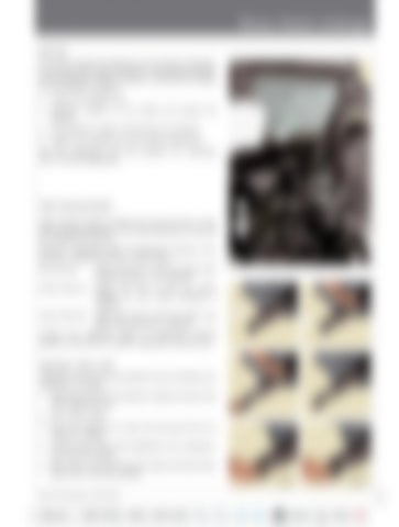
Draft Sensing Bracket
B
Draft sensing bracket transfers the top link force to the draft sensing mechanism. It has three holes (B), (C) and (D) for hitching the top link.
C D
Maximum achievable depth of implement increases as the top link is shifted from top to lower holes. Top Hole (B)
: Attach top link to hole (B) where draft sensing function is not required.
Centre Hole (C) : Attach top link to hole (C) where medium to Low draft sensitivity is required. Lower Hole (D) : Attach top link to hole (D) where very high draft sensitivity is required.
E F
Contact your Mahindra dealer to understand hitching position of top link for specific implements used by you.
Telescopic Lower Links Telescopic Lower Links are provided for ease of hitching the implement as follows, 1. Slowly back tractor into position to align the lower links with implement pins. 2. Park tractor safely. 3. Press the bracket (E) in lower link and pull link (F) to extend as needed. 4. Connect lower links to the implement. Sit on operator’s seat and start engine. 5. Back tractor until each lock lever snaps and secures each lower link in the lock position. Cat-I 35 Series PST-Cabin, Models - 3540P & 3550P
Cat-II 61


