6 minute read
Instrument Cluster


Parking Brake Indicator
It glows when parking brake or foot brake pedals (latched together) is applied.
Battery Charging Indicator
This indicator will glow if battery is not getting charged. Once the engine is running, this indicator should go OFF, if the Battery is getting charged. If the indicator glows continuously even when the engine is running above low idle rpm of the engine, the cause should be investigated to prevent complete discharge of battery and possible damage of alternator.
High Temperature Warning Indicator
This is RED Led marked as "High Temp" and is located in the Temperature Gauge. It will glow continuously when temperature of coolant rised above 1100C.
The pointer of Temperatur gauge will lie in the RED band under such condition.
Low Oil Pressure Indicator
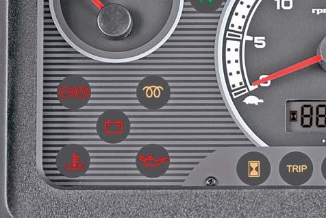
This indicator when glows indicates the engine operation at low lub oil pressure. The indicator will also glow alone when the key is in ON position before starting the engine and continue to glow till engine oil pressure builds up after starting the engine.
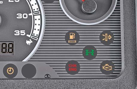
Water in Fuel Indicator
This indication will be ON when the water is accumulated in the fuel filter.
Air Filter Clog Indicator
It is ON when air filter requires periodic maintenance.
4WD Indicator
It glows when 4WD is engaged.
CHK ENG (Check Engine) Indicator
This indicator (E) will glow when the starter switch is turned to "ON" position. This indicator shall turn-off after engine is CRANKED.
A malfunction other than Emission, such as Sensor failures would be indicated by a continuously "GLOWING" or "BLINKING" Indicator, even past CRANKING of the engine. In such an event, get the problem rectified by an authorized Mahindra Dealer.
MIL (Malfunction) Indicator
This indicator (J) will glow when the starter switch is turned to "ON" position. This indicator shall turn-off after engine is CRANKED.
A malfunction in the electronic emission control system (ECU) is indicated by a continuously "GLOWING" or "BLINKING" Indicator, even past CRANKING of the engine. In such an event, get the problem rectified by an authorized Mahindra Dealer.
Switches
Following switches are provided for various operations.
Switches
Hazard Switch
The piano type switch is located below the combination switch on LH side of steering column on dashboard.
ON position operates LH, RH turn signal lamps simultaneously. This operation can be performed even if the key switch is in OFF position.
Switches
Switches
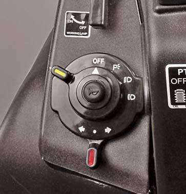
Combination Switch:
It is located in LH side of steering column on dashboard. It consists of:
1.Horn (in centre)
2.Light Switch

3.Turn Signal Switch
Horn
Pressing the horn switch will blow the horn.
Light Switch
It is a 4 positions rotary switch. It operates in clockwise direction and positions are as follows:
1.Off
2.Illuminate Parking Lamps
3.Illuminate low beam of head lamps & Parking Lamps
4.Illuminate high beam of head lamps & Parking Lamps
Turn Signal Switch
This is 3 positions rotary switch. The vertical position of knob operates in both directions and the positions are as follows:
1.Vertical - OFF
2.Left - Operates LH Turn signal Lamp
3.Right - Operates RH Turn Signal Lamp
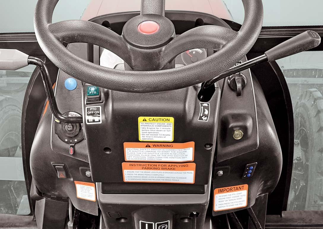
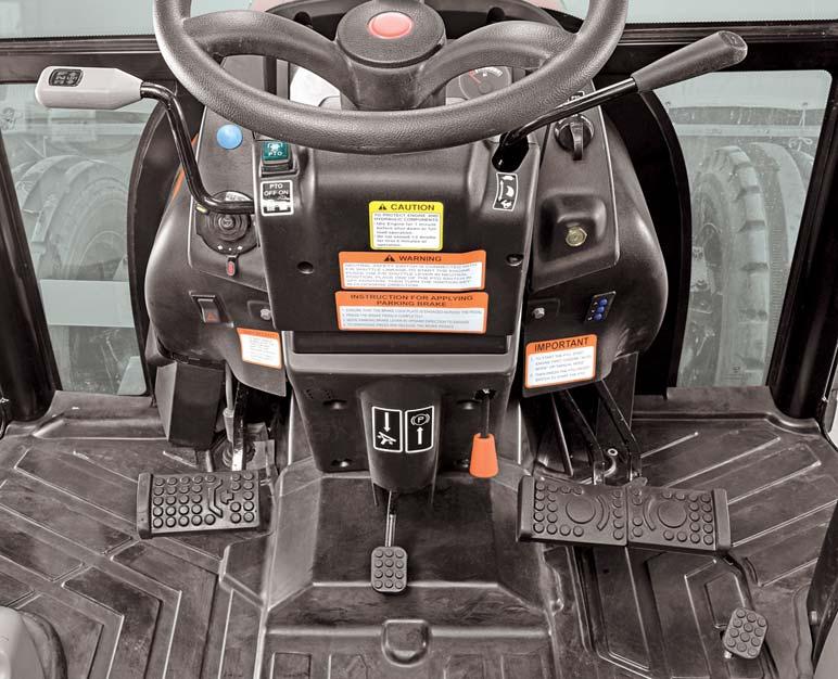
Starter Key Switch
It is a key operated 3 position rotary switch. It is located on RH side of steering column on dashboard. It operates in clockwise direction and positions are as follows:
1.Off
2.It gives readiness to electrical circuit for operation of work lamp switch, combination switch, instrument cluster.
3.Activates the starting circuit for engine.
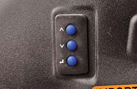
Key Pad Switch
This Switch is snap fitted on RH side of steering column on dash board. This is provided for digital ON/OFF signal to menu selection on LCD display of Instrument cluster.
NOTE : The starting circuit is interconnected with forward/reverse system & PTO system. Thus the engine will not start unless the forward/reverse pedal is in neutral & PTO Auto manual off switch in OFF condition.
PTO Operation Switches
PTO can be operated by using a combination of "PTO ON/OFF Switch" and "PTO Mode Switch".
To start the PTO, start engine first, choose "AUTO MODE" or "MANUAL MODE".
Then press the PTO ON/OFF switch to start the PTO.
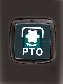
PTO ON/OFF Switch
This is a 2 in 1 switch, located on LH side of steering column on the dashboard.
1.Press the PTO switch to engage the PTO.
2.To disengage the PTO, press the PTO switch again.
PTO MODE switch (PTO Auto/Manual/Off Switch)
This rotary switch enables the operator to choose the AUTO or Manual mode of PTO and even turn-off the PTO when desired.
The Operating positions of knob are as follows:
1.Alignment of OFF - Mark with Pointer - PTO Turn-OFF
The Auto and Manual Mode switch will be activated when the “PTO Engage - Disengage Switch” is in ON position.
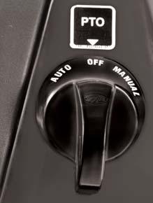
2.Alignment of Auto-mark with pointer - Operates
AUTO mode
This switch can be used when the “PTO Engage - Disengage Switch” is in ON position.
When this switch is in AUTO-POSITION, the PTO shaft rotation will be stopped as soon as the implement is raised. This will happen irrespective of clutch being engaged or disengaged. Such a situation is indicated by A BLINKING “PTO Engage - Disengage Switch”
While this switch is in AUTO-POSITION, IF the PC lever is lowered and clutch pedal released, the PTO shaft will become operative and will be indicated by a CONTINUOUSLY-GLOWING “PTO Engage - Disengage Switch”
While this switch is in AUTO-POSITION and the clutch pedal is pressed, the PTO shaft rotation will be stopped and indicated by A BLINKING “PTO Engage - Disengage Switch”
3.Alignment of Manual-mark with pointer - Operates Manual mode
This switch can be used when the “PTO Engage - Disengage Switch” is in ON position.
Keeping this switch in MANUAL-POSITION, will FORCE the PTO shaft rotation in RAISED as well as LOWERED position of implement. Even disengagement of clutch will not stop the PTO-SHAFT rotation. The “PTO Engage - Disengage Switch” will be CONTINUOUSLY-GLOWING when this switch is in MANUAL mode.
Tampered electrical wiring or connections will render this feature INEFFECTIVE. In such a case, some Inadvertent movement of personnel near the PTO shaft can prove fatal.
While the PTO is in MANUAL-MODE, some inadvertent movement of personnel near the PTO shaft can prove fatal.
Switches
POWER TAKE OFF
PTO is operated electrically. PTO can be operated by using a combination of “PTO Engage - Disengage Switch” and “PTO Mode Switch”.
After switching ON the “PTO Engage - Disengage Switch” the operator has a CHOICE to select AUTO or MANUAL MODE through “PTO Mode Switch”.
The PTO will turn-Off if the “PTO Engage - Disengage Switch” or “PTO Mode Switch” is in OFF position.
Refer table shown for combinations of PTO Operations.
PTO ON/OFF Switch PTO Control Switch Clutch PedalPC LeverPTO SwitchPTO Shaft
ONManual ModeEither pressedEither raisedGlowsRotates or releasedor lowered
ONAuto ModePressedEither raisedBlinksStationary or lowered
ONAuto ModeEither pressedRaisedBlinksStationary or released
ONAuto ModeReleasedLoweredGlowsRotates
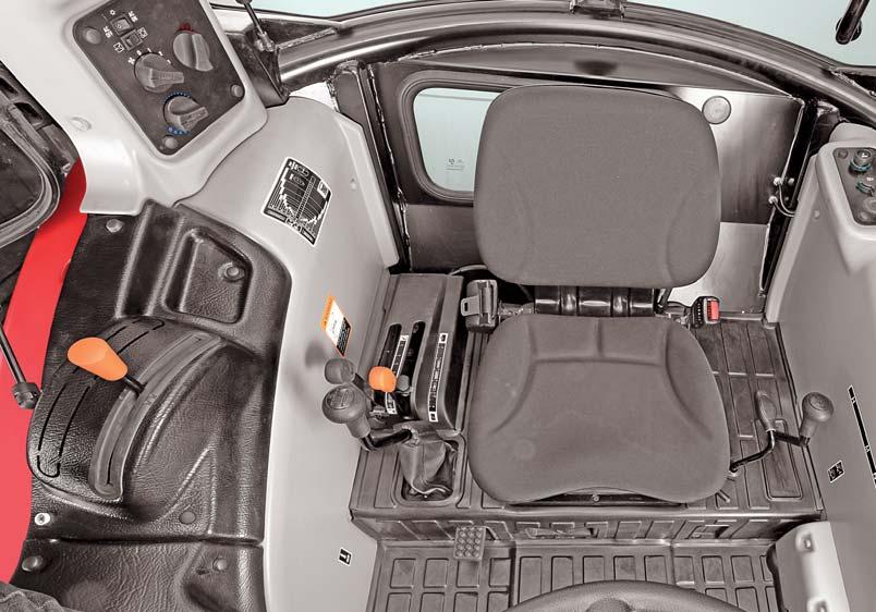
Controls
Operator Seat
The operator seat can be adjusted for position and weight of operator. These adjustments are to be done prior to starting the engine.
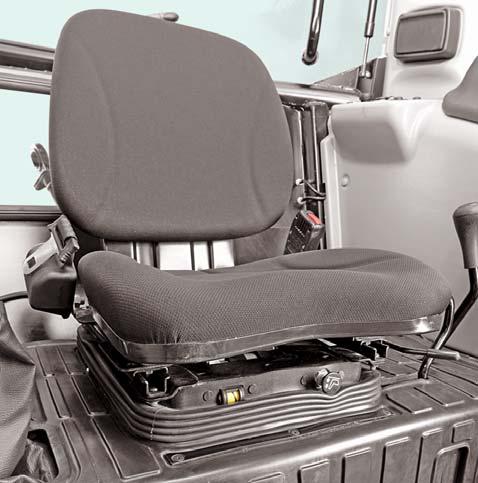
Adjusting Seat Position
1.Sit on the operator seat.
2.Push the lever (D) upwards and slide seat forward or rearward to desired position.
3.Release Lever to lock seat in position. Ensure that all controls can be accessed easily.
Height and Weight Adjustment
To achieve optimum seat suspension, press the knob (E) till you get the comfortable height and weight. This function can be activated with the ignition key at the Ignition position. It is operated by blower. Operator can hear a sound of air filling when the knob is pressed.
Pull the knob, to reduce the seat height or as per the weight requirements.
Using Seat belt
Use a seat belt to minimize chance of injury from an accident such as an overturn. Do not jump if machine tips.
Fasten Seat belt
1.Pull belt end (C) across operator lap.
2.Install tab into buckle (B). A click will be heard when the tab locks into the buckle.
Release Seat belt
Press red button (A). The seat belt will automatically retract.
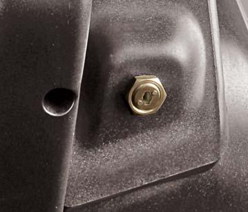
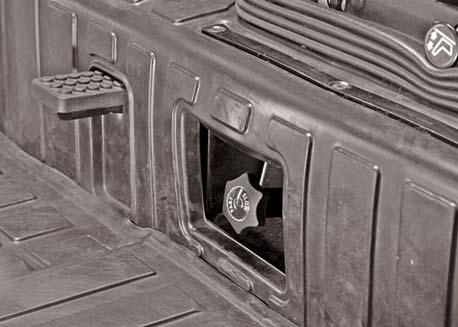
Slow Fast Valve Control Knob
3 Point Linkages drops faster when a heavy implement is attached. Adjust Slow/Fast Valve Knob (F) so that it is slow enough to be safe and prevent damage.
Turn the Slow/Fast Valve Knob, located on rear platform besides differential lock pedal, clockwise to slow rockshaft drop.
This knob is also called implement lock. When the knob is fully tightened in, implement will not lower down even if position control lever is fully down. Use implement lock while transporting implement.
Attempting to adjust the seat while driving the tractor may cause the operator to lose control of the tractor.
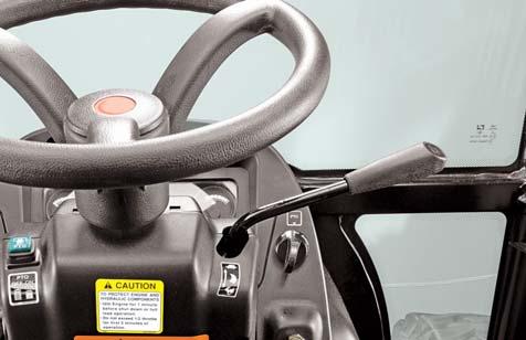
Hand Throttle Operation
Use the Hand Throttle Lever to set a constant engine speed for stationary operation or for field operation wherever desired.
Increasing Engine Speed : Pull throttle lever towards operator as indicated in the sticker on the dashboard.
Engine Tachometer Speeds : a.Low Idle speed - 1000 RPM b.Rated engine speed - 2800 RPM c.High Idle speed - 2975 RPM
Decreasing Engine Speed : Push throttle lever away from the operator as indicated in the sticker on the dashboard.
Constant Speed Setting : Certain operations may require a particular engine speed. This can be achieved by resting the Hand Throttle Lever in a position where you get the desired engine speed.
Foot Throttle Operation
When tractor operation requires repeated speed change, use the foot throttle pedal to temporarily increase engine speed above hand throttle setting. We recommend to keep the hand throttle at minimum and use foot throttle when driving on highway.
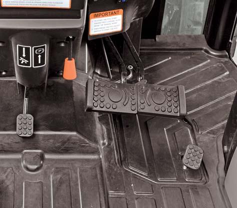
a.Set the hand throttle lever at desired RPM.
b.Depress foot throttle pedal to Increase Engine RPM.
c.Release foot throttle pedal to decrease Engine RPM to achieve the previous engine speed set by hand throttle lever.