7 minute read
Do's & Dont's


DO’S - Sensor (Phase Sensor)
DO-Phase Sensor should be unpacked directly before installation.
DO-Sensor to be mounted by pushing it into place.
DO-Clean and grease O-Ring prior to installation with mineral oil-based grease
DO-First support of wire after connection: Max 250 mm. It should be on the sensor carrier.
DO-Sensor terminal pins should be free from water/ moisture.
DO-Fix with only partially microcapsuled screw M6.
DO- Tightening Torque specification should be 8±0.5 Nm.
DO-Parts as delivered to assembly shall be clean and free of debris, residual abrasive material and corrosion products affecting function or appearance.
DO-The storage area must be dry, dust-free and within the permissible. storage temperature range. Direct sunlight must be avoided.
DO-Before mounting coat the seal ring with mineral based oil lubrication.
DO-Storage temperature: -40ºC to +80ºC at 0…80% humidity for 4 years.
DO’S - Sensor (Coolant Temperature Sensor)
DO-Protect parts against rain, snow and solar radiation and store them dry and dust-free.
DO-Storage temperature is -30ºC to 60ºC with relative humidity 0 to 60%
DO-During service - After removing temperature sensor, existing Aluminum washer is to be carefully cut (without damaging the brass threading) and taken out.
DO-Replace the washer with Copper washer.
DO’S - HP Pump
DO-Handle the pump by holding on to housing.
DO-Remove protection caps just before assembly.
DO-Fill the pump with 15ml of fuel before starting.
DO-Pre-fill with 35ml of Lube oil.
DO-MPROP connector to be connected / removed only in switch off condition.
DO’S - Solenoid Injector
DO-Keep the access of injector, clamping screw & support parallel while clamping.
DO-Ensure symmetrical force on to the injector body.
DO-Ensure HP connector is not loosened while tightening or loosening HPP nuts.
DO-Replace entire injector if HP connector is loosed.
DO-Use protection caps immediately after removal of injectors & interfaces.
DONT’S - Sensor (Phase Sensor)
DON’T-Don’t drop the sensor.
DON’T-Do not Hammer the sensor while fitting.
DON’T-Do not bend sensor wire between the connection and the first support.
DON’T-None of the application guidelines should be deviated ( Air gap etc).
DON’T-Sensor should not be kept near hot medium or objects with Temp > 160 ºC.
DON’T-The installation is made by pressing in and not forcing in with blunt instrument (e.g., hammer).
DON’T-The Phase sensor should be unpacked directly before installing in the car or on the test bench.
DON’T-Do not touch the sensor pins or the wiring harness pins with hand (to avoid ESD).
DON’T-If the sensor is taken out of its installation bore after having operated under thermal and mechanical loads, it is not allowed to put the same sensor back in the installation bore. Instead, it has to be replaced by a new sensor in order to ensure tightness.
DON’T-Mount sensor by pushing in (not knocking, no tools allowed) until seat of flange.
DONT’S - Sensor (Coolant Temperature Sensor)
DON’T-Don’t drop the sensor.
DON’T-Do not exceed the maximum permissible tightening torque is 25Nm.
DONT’S - HP Pump
DON’T-Do not try to disassemble or repair pump & external components.
DON’T-Do not remove pump inlet connector sieve filter.
DON’T-Do not change the banjo and hollow bolt.
DONT’S - Solenoid Injector
DON’T-Do not handle injectors by holding through connector & magnet group.
DON’T-Do not use tightening tools on magnet group.
DON’T-Do not remove the injector before removing electrical connection.
(For Service & Maintenance)
DO’S - Rail
DO-The rail should be mounted directly and rigidly on the engine block or cylinder head.
DO-Protect the rail assembly against external damages.
DO-Ensure the electrical connectors and wires are not in contact with hot engine parts and sharp edges.
DO-Protection caps to be placed immediately after the rail is removed.
DO’S
- Fuel Filter
DO-Ensure filter mounting nut & bolt tighten properly.
DO-Ensure inlet & outlet pipes are not interchanged.
DO-Ensure 250μm strainer is installed in the tank.
DO-Ensure that no leakage after cranking the engine.
DO-Store the filter in room temperature and under dry condition.
DO-Ensure water sensor is tightened properly.
DO-Change the sealing ring of the water sensor on every spin-on exchange.
DONT’S - Rail
DON’T-Do not mount the rail on the intake manifold or on intermediate brackets.
DON’T-Do not mount the rail close to exhaust manifold, turbocharger, EGR valve and other hot devices.
DON’T-Do not paint on the name plate and the add on of the rail.
DONT’S
- Fuel
Filter
DON’T-Do not use the physically damaged filter for assembly.
DON’T-Do not use hammer for tightening or loosening air vent screw and mounting fasteners.
DON’T-Do not install the filter in tilted angle or horizontally.
DON’T-Do not remove protection caps till fuel lines are connected.
DON’T-Do not fill the spin-on filter with diesel before mounting.
DON’T-Do not use wrenches for mounting.
DON’T-Do not use spin-on sealing ring more than one service interval.
DON’T-Do not unscrew the water level sensor completely.
DON’T-Do not let the diesel drain out from the filter while draining water.
DON’T-Do not repair the flap assembly in hand primer head assembly.
Maintenance
Cooling System
The cooling system consists of :
A.Radiator
B.Surge Tank
C.Fan
D.Thermostat
E.Water Pump
F.Fan Belts
G.Hoses & Connections
To ensure an even temperature within the engine, the cylinder head and cylinder walls of the engine are water cooled. This water is in turn cooled in the radiator. The water is circulated from the radiator to the engine and back through the radiator by means of a water pump.
Radiator
The radiator consists of a cluster of hollow tubes enshrined into a number of fins and enclosed at both ends vide a Top Tank and a bottom tank.
Air sucked by Fan passes through the radiator fins thereby cooling the coolant flowing through radiator tubes. The fins should be kept clear of mud or dirt accumulation. Over heating may be caused by bent or clogged radiator fins. If the spaces between the radiator fins become clogged, clean them with compressed air or coolant blown from engine side.
Radiator Cap
A pressurised radiator cap is provided which is set at 13 psi (0.9 kg/cm2) pressure. This cap ensures better cooling and avoids loss of coolant due to evaporation. It also reduces corrosion in engine sleeve & crankcase, hence it is strongly recommended that the engine should not be run without radiator cap. Also ensure that rubber gasket is intact & perfectly sealing the system pressure.
Surge Tank
When the engine is in operation, certain amount of coolant passes out of the radiator overflow pipe. This coolant is not allowed to escape into the atmosphere and captured into a Surge tank.
When the engine is not operating and the coolant cools down, certain amount of coolant comes back into the radiator from surge tank. The surge tank thus helps to prevent loss of coolant.
Thermostat
This device prevents coolant circulating through the radiator until the engine reaches its operating temperature. With the thermostat closed, the coolant circulates only through the engine block.
It is important that if the thermostat is defective, do not attempt to repair it, replace with new. When installing a new thermostat, ensure the valve is facing upward. The thermostat operating temperature is 1800F.
When straightening bent fins be careful not to damage the tubes or to break the bond between the fins and tubes.
The cooling system operates under pressure. It is dangerous to remove the radiator cap while the system is hot.
Always turn the cap slowly to the first stop, and allow pressure to escape before removing the cap completely.
Do not run the engine when the cooling system is empty, and do not add cold coolant or cold antifreeze solution if the engine is hot.
The coolant level in surge tank should not fall below the MIN level mark.
Do not run the Engine without Thermostat Valve.
Water Pump
The water pump is provided with a sealed bearing. Adjusting or greasing will not be necessary.
Hose Connections
Check periodically to ensure all the connections are in good order and the clips are tight. A leaking connection results in loss of coolant and thus engine efficiency. When using antifreeze in the cooling system, it is absolutely essential to have efficient connection so check these and should there be any doubt as to their serviceability, renew.
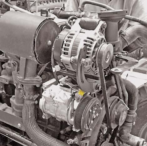
Fan & Fan Belts
A 6 Blade plastic fan is mounted on water pump and is driven vide fan belt by the main drive crank pulley. While the engine is in operation, the fan sucks air through the radiator core.
Slippage of belt on pulley can cause over heating. The Fan belts shall always be dry and free from oil or Grease. Incorrect belt tension results in its rapid wear. Crank pulley is assembled on crank shaft.
Belt Adjustment Alternator
To adjust belt tension, loosen the alternator on the adjustable bracket and lock the bolt in the location that gives correct belt tension of 70Hz, such that the belt can be depressed without much effort by the thumb, 0.25 to 0.4 inch.
Belt Adjustment Compressor
To adjust the belt tension on compressor, loosen the nut A and C and tight the bolt B to give the tension of 348 Hz.
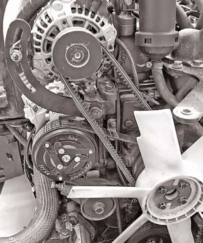
6pk "E" Belt Removal
1.Loosen the Nut (A).
2.Loosen the Bolt (B).
3.Loosen the Bolt (C).
4.Push the idler (D) out and remove the belt.
Single Groove V Belt "E" Removal
1.Loosen the Nut (A).
2.Loosen the Nut (B).

3.Loosen the Bolt (C).
4.Push the alternator (D) down and remove the belt.
Belt Replacement
Reverse the procedure of fan belt removal stated above. Adjust the fan belt tension as previously detailed.
Draining the System
Two drain plugs must be opened. One is on LH side of crankcase and one on radiator bottom tank. To speed up draining, remove the radiator cap. Ensure that the drains are not clogged. Close the taps after draining is complete.
Cleaning out Dirt and Sludge
Drain cooling system as directed above. Fill the cooling system with a solution of 1.0 Kg. of ordinary baking soda to 7.0 litres (1.84 US Gallons) of water. Do not replace the radiator cap. Operate the engine until the coolant is hot. Drain, flush with clean water and refill with a rust inhibitor or anti-freeze solution.