ELECTRICAL SYSTEM
B2301, B2601, WSM
[5] CHARGING SYSTEM (1) AC Dynamo Dynamo No-load Voltage 1. Disconnect the lead wires from the dynamo. 2. Start the engine, and check the generating voltage of the dynamo. Factory specification
14 to 15 V (at engine idling speed)
Voltage
9Y1211156ELS0025US0
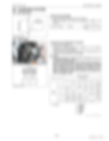
(2) Regulator Continuity across Regulator's Terminals 1. Remove the regulator (1). 2. Check with a tester whether the regulator (1) is in optimum condition or not as table below. 3. If the continuity is not measured as shown in the table below, the contacts of the regulators are damaged. NOTE • Use analog tester for measuring the continuity. Do not use insulation resistance tester. • On the check table below, "ON" means that the pointer of tester is swung and "OFF" means it is not swung. The value kΩ is reference value by measuring 1 kΩ range. And this value is changed by range, measurement tools and so on. • When measuring, remove wire harness and measure the value of regulator itself. Tester (+) terminal Tester (−) terminal
Cord colors
2
3
4
5
6
1
–
OFF
OFF
OFF
OFF
ON (7.1 kΩ)
2
OFF
–
OFF
OFF
OFF
OFF
3
OFF
OFF
–
OFF
OFF
ON (7.1 kΩ)
4
OFF
OFF
OFF
–
OFF
OFF
OFF
–
ON (7.1 kΩ)
OFF
OFF
–
5 6 (1) Regulator
Cord colors 1
ON ON ON (7.1 kΩ) (7.1 kΩ) (7.1 kΩ) OFF
OFF
OFF 1: 2: 3: 4: 5: 6:
Sky Blue Black Sky Blue Green Yellow Red 9Y1211156ELS0026US0
8-S17
KiSC issued 11, 2014 A


