11 minute read
[4] SERVICING

![6. SERVICING [1] STARTER](https://static.isu.pub/fe/default-story-images/news.jpg)
(1) Cylinder Head and Valves
Top Clearance
1.Remove the cylinder head. (Do not try to remove the cylinder head gasket.)
2.Move the piston up and stick a strip of fuse [1.5 mm dia. (0.059in. dia.), 5.0 to 7.0 mm long (0.20 to 0.27 in. long)] on the piston head at three positions with grease so as to avoid the intake valve and the exhaust valve and the combustion chamber ports.
3.Lower the piston, and install the cylinder head and tighten the cylinder head screws to the specified torque.
4.Turn the flywheel until the piston exceeds top dead center.
5.Remove the cylinder head, and measure the thickness of the squeezed fuses.
6.If the measurement is not within the factory specifications, check the oil clearance between the crankpin and the crankpin bearing and between the piston pin and the small end bushing.
NOTE
•After checking the top clearance, be sure to assemble the cylinder head with a new cylinder head gasket.
9Y1211156ENS0054US0
Cylinder Head Surface Flatness
1.Clean the cylinder head surface.
2.Place a straightedge on the cylinder head's four sides and two diagonal as shown in the figure.
3.Measure the clearance with a thickness gauge.
4.If the measurement exceeds the allowable limit, correct it with a surface grinder.
IMPORTANT
•Do not place the straightedge on the combustion chamber.
•Be sure to check the valve recessing after correcting.
9Y1211156ENS0055US0
Cylinder Head Flaw
1.Prepare an air spray red check.
2.Clean the surface of the cylinder head with detergent (2).
3.Spray the cylinder head surface with the red permeative liquid (1). Leave it five to ten minutes after spraying.
4.Wash away the read permeative liquid on the cylinder head surface with the detergent (2).
5.Spray the cylinder head surface with white developer (3).
6.If flawed, it can be identified as red marks.
9Y1211156ENS0056US0
Valve Recessing
1.Clean the cylinder head surface, the valve face and the valve seat.
2.Insert the valve into the valve guide.
3.Measure the valve recessing with a depth gauge.
4.If the measurement exceeds the allowable limit, replace the valve.
5.If it still exceeds the allowable limit after replacing the valve, replace the cylinder head.
9Y1211156ENS0057US0
Clearance between Valve Stem and Valve Guide
1.Remove carbon from the valve guide section.
2.Measure the valve stem O.D. with an outside micrometer.
3.Measure the valve guide I.D. with a small hole gauge, and calculate the clearance.
4.If the clearance exceeds the allowable limit, replace the valves. If it still exceeds the allowable limit, replace the valve guide.
9Y1211156ENS0058US0
Replacing Valve Guide
(When removing)
1.Press out the used valve guide using a valve guide replacing tool. (See page "SPECIAL TOOLS".)
(When installing)
1.Clean a new valve guide and valve guide bore, and apply engine oil to them.
2.Press in a new valve guide using a valve guide replacing tool.
3.Ream precisely the I.D. of the valve guide to the specified dimension.
IMPORTANT
•Do not hit the valve guide with a hammer during replacement.
9Y1211156ENS0059US0
Valve Seating
1.Coat the valve face lightly with prussian blue and put the valve on its seat to check the contact.
2.If the valve does not seat all the way around the valve seat or the valve contact is less than 70 %, correct the valve seating as follows.
3.If the valve contact does not comply with the reference value, replace the valve or correct the contact of valve seating.
9Y1211156ENS0060US0
Correcting Valve and Valve Seat NOTE
•Before correcting the valve and the seat, check the valve stem and the I.D. of valve guide section, and repair them if necessary.
•After correcting the valve seat, be sure to check the valve recessing.
1) Correcting Valve
1.Correct the valve with a valve refacer.
2) Correcting Valve Seat
1.Slightly correct the seat surface with a 0.79 rad (45 °) / 1.0rad (60 °) valve seat cutter.
2.Fitting the valve, check the contact position of the valve face and seat surface with prussian blue. (Visual check) [If the valve has been used for a long period, the seat tends to come in contact with the upper side of the valve face.]
3.Grind the upper surface of the seat with a 0.52 rad (30 °) valve seat cutter until the valve seat touches to the center of the valve face (so that (a) equals (b) as shown in the figure).
4.Grind the seat with a 0.26 rad (15 °) valve seat cutter again, and visually recheck the contact between the valve and the seat.
5.Repeat steps 3 and 4 until the correct contact is achieved.
6.Continue lapping until the seated rate becomes more than 70 % of the total contact area.
9Y1211156ENS0061US0
Valve Lapping
1.Apply compound evenly to the valve lapping surface.
2.Insert the valve into the valve guide. Lap the valve onto its seat with a valve flapper or screwdriver.
3.After lapping the valve, wash the compound away and apply oil, then repeat valve lapping with oil.
4.Apply prussian blue to the contact surface to check the seated rate. If it is less than 70 %, repeat valve lapping again.
IMPORTANT
•When valve lapping is performed, be sure to check the valve recessing and adjust the valve clearance after assembling the valve. 9Y1211156ENS0062US0
Free Length and Tilt of Valve Spring
1.Measure the free length (B) of valve spring with vernier calipers. If the measurement is less than the allowable limit, replace it.
2.Put the valve spring on a surface plate, place a square on the side of the valve spring.
3.Check to see if the entire side is in contact with the square. Rotate the valve spring and measure the maximum tilt (A) If the measurement exceeds the allowable limit, replace it.
4.Check the entire surface of the valve spring for scratches.If there is any problem, replace it.
9Y1211156ENS0063US0
Valve Spring Setting Load
1.Place the valve spring on a tester and compress it to the same length it is actually compressed in the engine.
2.Read the compression load on the gauge.
3.If the measurement is less than the allowable limit, replace it.
9Y1211156ENS0064US0
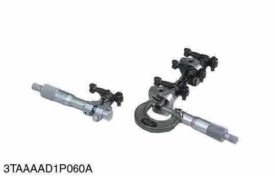
Oil Clearance between Rocker Arm and Rocker Arm Shaft
1.Measure the rocker arm shaft O.D. with an outside micrometer.
2.Measure the rocker arm I.D. with an inside micrometer, and then calculate the oil clearance.
3.If the oil clearance exceeds the allowable limit, replace the rocker arm and measure the oil clearance again. If it still exceeds the allowable limit, replace also the rocker arm shaft.
9Y1211156ENS0065US0
(2) Idle Gear and Camshaft
Push Rod Alignment
1.Place the push rod on V blocks.
2.Measure the push rod alignment.
3.If the measurement exceeds the allowable limit, replace the push rod.
9Y1211156ENS0066US0
Oil Clearance between Tappet and Tappet Guide Bore
1.Measure the tappet O.D. with an outside micrometer.
2.Measure the I.D. of the tappet guide bore with a cylinder gauge, and calculate the oil clearance.
3.If the oil clearance exceeds the allowable limit or the tappet is damaged, replace the tappet.
9Y1211156ENS0067US0
Timing Gear Backlash
1.Set a dial indicator (lever type) with its tip on the gear tooth.
2.Move the gear to measure the backlash, holding its mating gear.
3.If the backlash exceeds the allowable limit, check the oil clearance of the shafts and the gear.
4.If the oil clearance is proper, replace the gear.
9Y1211156ENS0068US0
Idle Gear 1 and 2 Side Clearance
1.Set a dial indicator with its tip on the idle gear.
2.Measure the side clearance by moving the idle gear to the front and rear.
3.If the measurement exceeds the allowable limit, replace the idle gear collar.
9Y1211156ENS0069US0
Camshaft Side Clearance
1.Set a dial indicator with its tip on the camshaft.
2.Measure the side clearance by moving the cam gear to the front to rear.
3.If the measurement exceeds the allowable limit, replace the camshaft stopper.
9Y1211156ENS0070US0
Camshaft Alignment
1.Support the camshaft with V blocks on the surface plate at both end journals.
2.Set a dial indicator with its tip on the intermediate journal.
3.Measure the camshaft alignment.
4.If the measurement exceeds the allowable limit, replace the camshaft. 9Y1211156ENS0071US0
Cam Height
1.Measure the height of the cam at its highest point with an outside micrometer.
2.If the measurement is less than the allowable limit, replace the camshaft.
Oil Clearance of Camshaft Journal
1.Measure the camshaft journal O.D. with an outside micrometer.
2.Measure the cylinder block bore I.D. for camshaft with a cylinder gauge, and calculate the oil clearance.
3.If the oil clearance exceeds the allowable limit, replace the camshaft.
(3) Piston and Connecting Rod
Replacing Idle Gear Bushing
(When removing)
1.Press out the used idle gear bushing using an idle gear bushing replacing tool. (See page "SPECIAL TOOLS".)
(When installing)
1.Clean a new idle gear bushing and idle gear bore, and apply engine oil to them.
2.Press in a new bushing using an idle gear bushing replacing tool, until it is flush with the end of the idle gear.
Piston Pin Bore I.D.
1.Measure the piston pin bore I.D. in both the horizontal and vertical directions with a cylinder gauge.
2.If the measurement exceeds the allowable limit, replace the piston. 9Y1211156ENS0075US0
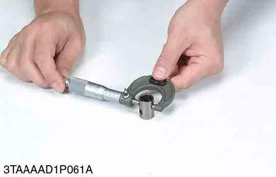
Oil Clearance between Piston Pin and Small End Bushing
1.Measure the piston pin O.D. where it contacts the bushing with an outside micrometer.
2.Measure the small end bushing I.D. with an inside micrometer, and calculate the oil clearance.
3.If the oil clearance exceeds the allowable limit, replace the bushing. If it still exceeds the allowable limit, replace the piston pin.
9Y1211156ENS0076US0
Replacing Small End Bushing
(When removing)
1.Press out the used bushing using a small end bushing replacing tool. (See page "SPECIAL TOOLS".)
(When installing)
1.Clean a new small end bushing and bore, and apply engine oil to them.
2.Using a small end bushing replacing tool, press in a new bushing (service parts) taking care to see that the connecting rod oil hole matches the bushing hole. 9Y1211156ENS0077US0
Piston Ring Gap
1.Insert the piston ring into the lower part of the cylinder (the least worn out part) with a piston.
2.Measure the ring gap with a thickness gauge.
3.If the measurement exceeds the allowable limit, replace the piston ring.
Piston ring gap Top ring
Piston ring gap Factory specification 0.15 to 0.25 mm 0.0059 to 0.0098 in. Allowable limit 1.20 mm 0.0472 in. Second ring
Factory specification 0.40 to 0.55 mm 0.016 to 0.021 in. Allowable limit 1.20 mm 0.0472 in. Oil ring
Factory specification 0.25 to 0.45 mm 0.0091 to 0.017 in. Allowable limit 1.25 mm 0.0492 in.
9Y1211156ENS0078US0
Clearance between Piston ring and Piston Ring Groove
1.Clean the rings and the ring grooves, and install each ring in its groove.
2.Measure the clearance between the ring and the groove with a feeler gauge or depth gauge.
3.If the clearance exceeds the allowable limit, replace the piston ring.
4.If the clearance still exceeds the allowable limit with new ring, replace the piston.
Clearance between piston ring and piston ring groove
Second ring Factory specification 0.0950 to 0.122 mm 0.00374 to 0.00480 in. Allowable limit 0.2 mm 0.008 in. Oil ring Factory specification 0.020 to 0.060 mm 0.00079 to 0.0023 in. Allowable limit 0.15 mm 0.0059 in. KiSC issued 11, 2014 A
(4) Crankshaft
Connecting Rod Alignment
1.Remove the crankpin bearing, and install the connecting rod cap.
2.Install the piston pin in the connecting rod.
3.Install the connecting rod on the connecting rod alignment tool.
4.Put a gauge over the piston pin, and move it against the face plate.
5.If the gauge does not fit squarely against the face plate, measure the space between the pin of the gauge and the face plate.
6.If the measurement exceeds the allowable limit, replace the connecting rod.
9Y1211156ENS0080US0
Crankshaft Side Clearance
1.Set a dial indicator with its tip on the end of the crankshaft.
2.Measure the side clearance by moving the crankshaft to the front and rear.
3.If the measurement exceeds the allowable limit, replace the thrust bearings.
4.If the same size bearing is useless because of the crankshaft journal wear, replace it with an oversize one referring to the table and figure.
(Reference)
•Oversize dimensions of crankshaft journal
Crankshaft Alignment
1.Support the crankshaft with V blocks on the surface plate at both end journals.
2.Set a dial indicator with its tip on the intermediate journal.
3.Measure the crankshaft alignment.
4.If the measurement exceeds the allowable limit, replace the crankshaft.
Oil Clearance between Crankpin and Crankpin Bearing
1.Clean the crankpin and crankpin bearing.
2.Put a strip of plastigauge on the center of the crankpin.
3.Install the connecting rod cap and tighten the connecting rod screws to the specified torque, and remove the cap again.
4.Measure the amount of the flattening with the scale, and get the oil clearance.
5.If the oil clearance exceeds the allowable limit, replace the crankpin bearing.
6.If the same size bearing is useless because of the crankpin wear, replace it with an undersize one referring to the table and figure.
Note
•Never insert the plastigauge into the crankpin oil hole.
•Be sure not to move the crankshaft while the connecting rod screws are tightened.
(Reference)
•Undersize
The crankpin must be fine-finished to higher than Rmax = 0.8S. *Holes to be de-burred and edges rounded with 1.0 to 1.5 mm (0.040 to 0.059 in.) relief.
9Y1211156ENS0083US0
Oil Clearance between Crankshaft Journal and Crankshaft Bearing 1
1.Measure the O.D. of the crankshaft front journal with an outside micrometer.
2.Measure the I.D. of the crankshaft bearing 1 with an inside micrometer, and calculate the oil clearance.
3.If the clearance exceeds the allowable limit, replace the crankshaft bearing 1.
4.If the same size bearing is useless because of the crankshaft journal wear, replace it with an undersize one referring to the table and figure.
(Reference)
•Undersize dimensions of crankshaft journal
The crankshaft journal must be fine-finished to higher than Rmax = 0.8S. *Holes to be de-burred and edges rounded with 1.0 to 1.5 mm (0.040 to 0.059 in.) relief.
9Y1211156ENS0084US0
Replacing Crankshaft Bearing 1
(When removing)
1.Press out the used crankshaft bearing 1 using a crankshaft bearing 1 replacing tool. (See page "SPECIAL TOOLS".)
(When installing)
1.Clean a new crankshaft bearing 1 and crankshaft journal bore, and apply engine oil to them.
2.Using a crankshaft bearing 1 replacing tool, press in a new bearing 1 (2) so that its seam (1) directs toward the exhaust manifold side. (See figure.)
9Y1211156ENS0085US0
Oil Clearance between Crankshaft Journal and Crankshaft Bearing 2 (Crankshaft Bearing 3)
1.Put a strip of plastigauge on the center of the journal.
2.Install the bearing case and tighten the baring case screws 1 to the specified torque, and remove the bearing case again.
3.Measure the amount of the flattening with the scale and get the oil clearance.
4.If the clearance exceeds the allowable limit, replace the crankshaft bearing 2 (1) and crankshaft bearing (3).
5.If the same size bearing is useless because of the crankshaft journal wear, replace it with an undersize one referring to the table and figure.
NOTE
•Be sure not to move the crankshaft while the bearing case screws are tightened. (Reference)
•Undersize dimensions of crankshaft journal
9Y1211156ENS0086US0
(5) Cylinder
Cylinder Wear
1.Measure the I.D. of the cylinder at the six positions (see figure) with a cylinder gauge to find the maximum and minimum I.D.'s.
2.Get the difference (Maximum wear) between the maximum and the minimum I.D.'s.
3.If the wear exceeds the allowable limit, bore and hone to the oversize dimension. (Refer to "Correcting Cylinder".)
4.Visually check the cylinder wall for scratches. If deep scratches are found, the cylinder should be bored. (Refer to "Correcting Cylinder".)
Cylinder I.D.
(6) Oil Pump
(A)Top (B)Middle
(C)Bottom (Skirt)
Correcting Cylinder
(a)Right-angled to Piston Pin
(b)Piston Pin Direction
9Y1211156ENS0087US0
1.When the cylinder is worn beyond the allowable limit, bore and hone it to the specified dimension.
2.Replace the piston and piston rings with oversize ones. Oversize: 0.5 mm (0.02 in.)
NOTE
•When the oversize cylinder is worn beyond the allowable limit, replace the cylinder block with a new one.
(1)Cylinder
Rotor Lobe Clearance
9Y1211156ENS0088US0
1.Measure the clearance between lobes of the inner rotor and the outer rotor with a feeler gauge.
2.If the clearance exceeds the factory specifications, replace the oil pump rotor assembly.
9Y1211156ENS0089US0
Clearance between Outer Rotor and Pump Body
1.Measure the clearance between the outer rotor and the pump body with a feeler gauge.
2.If the clearance exceeds the factory specifications, replace the oil pump rotor assembly.
9Y1211156ENS0090US0
Clearance between Rotor and Cover
1.Put a strip of plastigauge onto the rotor face with grease.
2.Install the cover and tighten the screws.
3.Remove the cover carefully, and measure the amount of the flattening with the scale and get the clearance.
4.If the clearance exceeds the factory specifications, replace the oil pump rotor assembly.
9Y1211156ENS0091US0