7 minute read
4. CHECKING, DISASSEMBLING AND SERVICING

![6. SERVICING [1] STARTER](https://static.isu.pub/fe/default-story-images/news.jpg)
[1] CHECKING AND ADJUSTING
(1) Engine Body
Compression Pressure
1.Operate the engine until it is warmed up.
2.Stop the engine.
3.Remove the air cleaner, the muffler and all glow plugs (or nozzles).
4.Set a compression tester with the adaptor to the glow plug hole (or nozzle hole).
Nozzle Hole: Adaptor H Glow Plug Hole: Adaptor L
5.After making sure that the stop lever is set at the stop position (non-injection), operate the engine with the starter and measure the compression pressure.
6.Repeat steps 4 and 5 for each cylinder.
7.If the measurement is below the allowable limit, apply a small amount of oil to the cylinder wall through the glow plug hole (or nozzle hole) and measure the compression pressure again.
8.If the compression pressure is still less than the allowable limit, check the top clearance, valve clearance and cylinder head.
9.If the compression pressure increases after applying oil, check the cylinder wall and piston rings.
NOTE
•Check the compression pressure with the specified valve clearance.
•Always use a fully charged battery for performing this test.
•Variances in cylinder compression values should be under 10 %.
Valve Clearance 1
Important
•Valve clearance must be checked and adjusted when engine is cold.
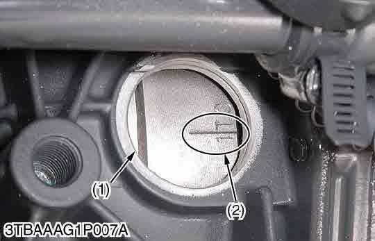
1.Remove the head cover, the glow plugs and the timing window cover on the clutch housing.
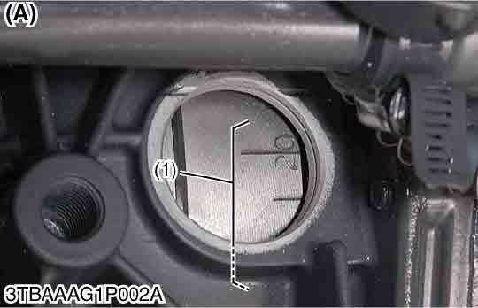
2.Align the "1TC" mark line on the flywheel and center of timing window so that the No. 1 piston comes to the compression top dead center.
3.Check the following valve clearance marked with "" using a feeler gauge.
4.If the clearance is not within the factory specifications, adjust with the adjusting screw.
Note
•The "TC" marking line on the flywheel is just for No. 1 cylinder. There is no "TC" marking for the other cylinders.
•No. 1 piston comes to the T.D.C. position when the "TC" marking line is aligned with center of timing window on front case. Turn the flywheel 0.26 rad (15 °) clockwise and counterclockwise to see if the piston is at the compression top dead center or the overlap position. Now referring to the table below, readjust the valve clearance. (The piston is at the compression top dead center when both the IN. and EX. valves do not move; it is at the overlap position when both the valves move.)
•Finally turn the flywheel 6.28 rad (360 °) and align the "TC" marking line and the center of timing window. Adjust all the other valve clearance as required.
•After turning the flywheel counterclockwise twice or three times, recheck the valve clearance, firmly tighten the lock nut of the adjusting screw.
: Valve clearance is adjustable.
(2) Lubricating System
Engine Oil Pressure
1.Remove the engine oil pressure switch, and set an oil pressure tester.
2.Start the engine. After warming up, measure the oil pressure of both idling and rated speeds.
3.If the oil pressure is less than the allowable limit, check the following.
•Engine oil insufficient
•Oil pump damaged
•Oil strainer clogged
•Oil filter cartridge clogged
•Oil gallery clogged
•Excessive oil clearance
•Foreign matter in the relief valve
Engine
(When reassembling)
•After checking the engine oil pressure, tighten the engine oil pressure switch to the specified torque.
(3) Cooling System
Fan Belt Tension
9Y1211156ENS0008US0
1.Measure the deflection (A), depressing the belt halfway between the fan drive pulley and dynamo pulley at specified force (98 N, 10 kgf, 22 lbf).
2.If the measurement is not within the factory specifications, loosen the dynamo mounting screws and relocate the dynamo to adjust.
9Y1211156ENS0009US0
Fan Belt Damage and Wear
1.Check the fan belt for damage.
2.If the fan belt is damaged, replace it.
3.Check if the fan belt is worn and sunk in the pulley groove.
4.If the fan belt is nearly worn out and deeply sunk in the pulley groove, replace it.
9Y1211156ENS0010US0
Thermostat Valve Opening Temperature
1.Suspend the thermostat in the water by a string with its end inserted between the valve and seat.
2.Heating the water gradually, read the temperature when the valve opens and leaves the string.
3.Continue heating and read the temperature when the valve opens approx. 8 mm (0.3 in.).
4.If the measurement is not within the factory specifications, replace the thermostat. 9Y1211156ENS0011US0
Caution
•When removing the radiator cap, wait at least ten minutes after the engine has stopped and cooled down. Otherwise, hot water may gush out, scalding nearby people.
9Y1211156ENS0012US0
Radiator Cap Air Leakage
1.Set a radiator tester (1) and adaptor (2) on the radiator cap.
2.Apply the specified pressure 88 kPa (0.89 kgf/cm2, 12 psi), and measure the time for the pressure to fall to 59 kPa (0.61 kgf/cm2, 8.6 psi).
3.If the measurement is less than the factory specification, replace the radiator cap.
9Y1211156ENS0013US0
Radiator Water Leakage
1.Pour a specified amount of water into the radiator.
2.Set a radiator tester (1) and an adaptor (2) and raise the water pressure to the specified pressure.
3.Check the radiator for water leaks.
4.For water leak from the pinhole, repair with the radiator cement. When water leak is excessive, replace the radiator.
9Y1211156ENS0014US0
(4) Fuel System
Injection Timing
1.Remove the injection pipes.
2.Remove the engine stop solenoid.
3.Turn the flywheel counterclockwise (facing the flywheel) until fuel flows from the delivery valve holder.
4.Continue to turn the flywheel slowly, and stop it as soon as the fuel level at the tip of the delivery valve holder begins to increase.
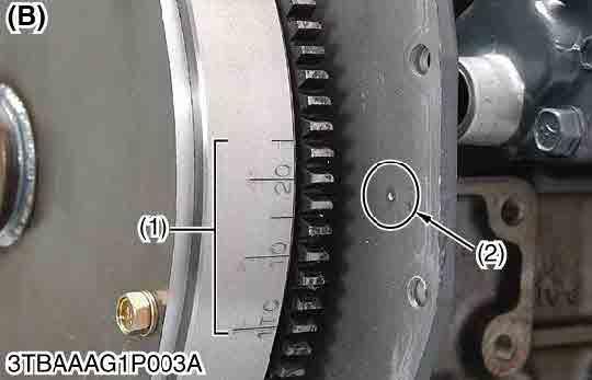
5.Check to see if the timing angle lines on the flywheel is aligned with the alignment mark (2).
6.If the injection timing is out of adjustment, readjust the timing with shims.
Note
•The sealant is applied to both sides of the shim (soft metal gasket shim). The liquid gasket is not required for assembling.
•Shims are available in thickness of 0.20 mm (0.0079 in.), 0.25 mm (0.0098 in.), 0.30 mm (0.012 in.), 0.35 mm (0.014 in.) and 0.175 mm (0.00689 in.). Combine these shims for adjustments.
•Addition or reduction of shim (0.025 mm, 0.00098 in.) delays or advances the injection timing by approx. 0.0044rad (0.25°).
•In disassembling and replacing the injection pump, be sure to use the same number of new shims with the same thickness.
•Refer to figure below to check the thickness of the shims.
(1)Timing Line
(2)Alignment Mark
(3)Shim (Soft Metal Gasket Shim)
(4)Two-holes: 0.20 mm (0.0079 in.)
Two-holes: 0.175 mm (0.00689 in.)
(5)One-hole: 0.25 mm (0.0098 in.)
(6)Without hole: 0.30 mm (0.012 in.)
(7)Three-holes: 0.35 mm (0.014 in.)
Fuel Tightness of Pump Element
1.Remove the engine stop solenoid.
2.Remove the injection pipes and glow plugs.
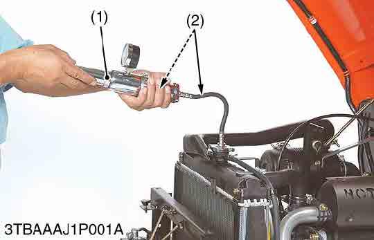
3.Install the injection pump pressure tester to the injection pump.
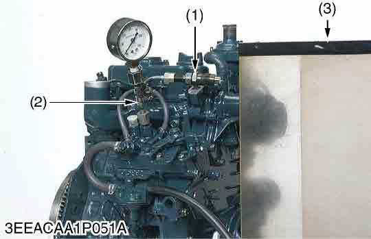
4.Install the injection nozzle (1) jetted with the proper injection pressure to the injection pump pressure tester (2). (Refer to the photo.).
5.Set the speed control lever to the maximum speed position.
6.Operate the starter to increase the pressure.
7.If the pressure can not reach the allowable limit, replace the pump with new one or repair with a Kubota-authorized pump service shop.
Note
•Never try to disassemble the injection pump assembly. For repairs, you are strongly requested to contact a Kubota-authorized pump service shop.
9Y1211156ENS0016US0
Fuel Tightness of Delivery Valve
1.Remove the engine stop solenoid.
2.Remove the injection pipes and glow plugs.
3.Set a pressure tester to the fuel injection pump.
4.Install the injection nozzle (1) jetted with the proper injection pressure to the injection pump pressure tester (2).
5.Operate the starter to increase the pressure.
6.Stop the starter when the fuel jets from the injection nozzle. After that, turn the flywheel by the hand and raise the pressure to approx. 13.73 MPa (140 kgf/cm2, 1991 psi).
7.Now turn the flywheel back about half a turn (to keep the plunger free). Keep the flywheel at this position and clock the time taken for the pressure to drop from 13.73 to 12.75 MPa (from 140 to 130 kgf/cm2, from 1991 to 1849 psi).
8.Measure the time needed to decrease the pressure from 13.73 to 12.75 MPa (from 140 to 130 kgf/cm2, from 1991 to 1849 psi).
9.If the measurement is less than allowable limit, replace the pump with new one or repair with a Kubota-authorized pump service shop.
•Never try to disassemble the injection pump assembly. For repairs, you are strongly requested to contact a Kubota-authorized pump service shop.
9Y1211156ENS0017US0
Nozzle Spraying Condition
Caution
•Check the injection pressure and condition after you make sure that there is nobody standing in the direction the fume goes.
•If the fume from the nozzle directly injects the human body, cells may be destroyed and blood poisoning may be caused.
•Use eyes protector on eyes before inspecting the high pressure fuel from the fuel injection nozzle temporarily.
•Set the protection board for jetted fuel near the tractor before inspecting the high pressure fuel from the injection nozzle temporarily.
•Use face protector on face before inspecting the high pressure fuel from the fuel injection nozzle temporarily.
•Use leather gloves or protector on hands, arm covers on arms and protector on body before inspecting the high pressure fuel from the fuel injection nozzle temporarily.
1.Set the injection nozzle to a nozzle tester, and check the nozzle spraying condition.
2.If the spraying condition is damaged, replace the nozzle piece.
(a)Good (b)Bad
Fuel Injection Pressure
1.Set the injection nozzle to a nozzle tester.
9Y1211156ENS0018US0
2.Slowly move the tester handle to measure the pressure at which fuel begins jetting out from the nozzle.
3.If the measurement is not within the factory specifications, replace the adjusting washer (1) in the nozzle holder to adjust it.
Fuel injection pressure Factory specification
(Reference)
13.73 to 14.71 MPa 140 to 150 kgf/cm2 1990 to 2130 psi
•Pressure variation with 0.01 mm (0.0004 in.) difference of adjusting washer thickness: Approx. 235 kPa (2.4 kgf/cm2, 34 psi)
(1)Adjusting Washer
9Y1211156ENS0019US0
Valve Seat Tightness
1.Set the injection nozzle to a nozzle tester.
2.Raise the fuel pressure, and keep at 12.75 MPa (130 kgf/cm2, 1849 psi) for 10 seconds.
3.If any fuel leak is found, replace the nozzle piece.
Valve seat tightnessFactory specification No
Nozzle Holder
9Y1211156ENS0020US0
1.Secure the nozzle retaining nut (7) with a vise.
2.Remove the nozzle holder (1), and remove parts inside. (When reassembling)
•Assemble the nozzle in clean fuel oil.
•Install the push rod (4), noting its direction.
•After assembling the nozzle, be sure to adjust the fuel injection pressure.
(1)Nozzle Holder
(2)Adjusting Washer
(3)Nozzle Spring
(4)Push Rod
(5)Distance Piece
(6)Nozzle Piece
(7)Nozzle Retaining Nut
9Y1211156ENS0021US0