1 minute read
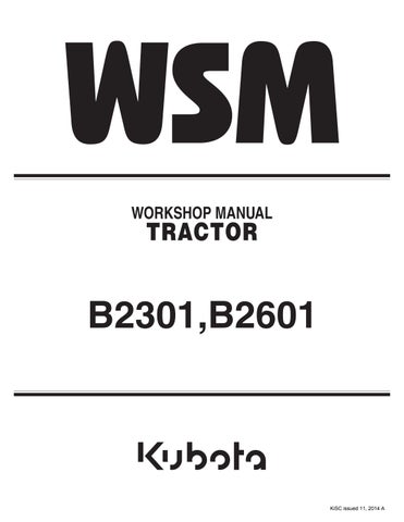
(2) Operation


Neutral
Oil forced into the control valve through P port pushes and opens the unload valve (3), and opens the unload valve (3), and then returns to the transmission case through T1 port.
Oil behind the unload valve (3) returns to the transmission case through the groove of the spool (2).
Since the check valve (9) and the poppet 2 (5) are closed, oil in the hydraulic cylinder does not flow to the transmission case. Thus, the implement remains at its fixed position.
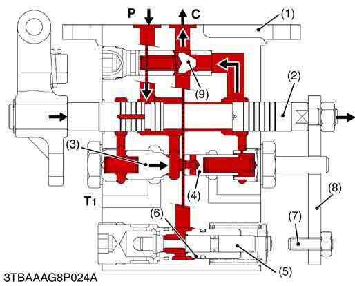
Lift
When the position control lever is set to "LIFT" position, the spool (2) is pushed into the valve body (1). The oil forced into the control valve body (1) through P port flows to two oil circuits.
The first circuit is oil flowing to the back of the unload valve (3) to close it.
The second oil circuit is oil flowing to the check valve (9) and the hydraulic cylinder through C port to lift the implement.
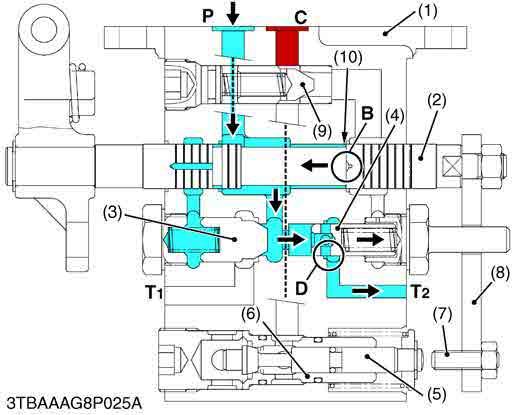
Shockless mechanism operating (Lift to Neutral)
When the implement begins to lift up, the feedback rod connected to the lift arm pushes back the spool (2) to near "NEUTRAL" position.
When the implement lifts up near the "NEUTRAL" position, quantity of oil passing through the orifice (10) is reduced.
It causes oil pressure difference between portion B and unload poppet (4).
Since oil pressure at unload poppet (4) is higher than oil pressure at portion D, oil forced from P port pushes and opens unload poppet (4), and oil drains through T2 port to transmission case.
Quantity of oil flowing through portion B is less.
Quantity of oil flowing to unload poppet (4) is greater. It causes oil pressure increase at portion D of the unload poppet (4).
While the implement is coming to "NEUTRAL" position, quantity of oil flowing to spool (2) is reduced at portion B. And then, oil drains through unload poppet (4) to transmission case.
It causes implement's smooth stopping at "NEUTRAL" position without shock.
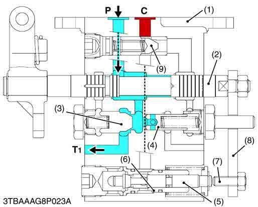
9Y1211156HYM0008US0 Down
When the position control lever is set to "DOWN" position, the spool (2) is pulled out from the control valve body (1).
At the same time, the adjust bolt (7) connected to the connecting plate (8) pushes the poppet 2 (5) into the control valve body (1). And then the poppet 2 (5) is opened.
Oil in the hydraulic cylinder is forced out from C port through and goes valve body (1) to transmission case by the weight of the implement, causing the implement to lower.
Oil forced into the control valve through P port pushes and opens the unload valve (3) and returns to the transmission case through T1 port.