2 minute read
1 ENGINE

![6. SERVICING [1] STARTER](https://static.isu.pub/fe/default-story-images/news.jpg)
1. ENGINE BODY [1] CLOSED BREATHER
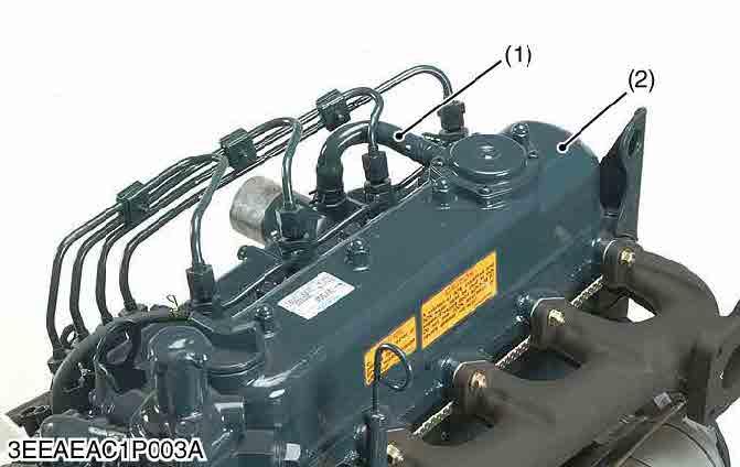
Closed breather system has been adopted to prevent the release of blow-by gas into the atmosphere. After its oil content is filtered by oil shield (4), the blow by gas in fed back to the intake manifold through breather valve (3) to be used for re-combustion.
(1)Breather Tube
(2)Cylinder Head Cover
(3)Breather Valve
(4)Oil Shield
(5)Rubber Packing
9Y1211156ENM0001US0
Three Lever Type Fork Lever
The governor system is a mechanical governor that used the flyweight (5).
The flyweight (5) is mounted on the governor shaft that rotates at the same speed as the crankshaft.
Because the feature of this mechanism takes out the engine speed directly as a centrifugal force of weight, the speed control that the change in the engine rotational speed is sensitively transmitted to fork lever assembly (A) and accuracy is high is enabled.
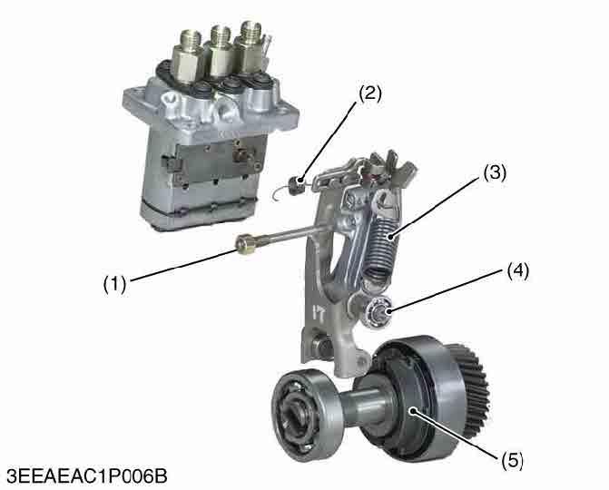
The fork lever assembly of this engine consists of fork lever 1 (6), for lever 2 (9), and the floating lever (7). A slide plate is installed in fork lever 1. The governor spring (3) is hooked to fork lever 2 (9).
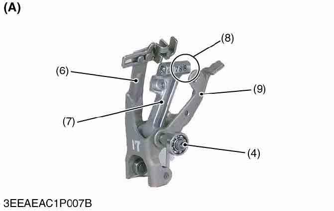
The floating lever (7) installs the torque pin (8) of the output drop prevention at the overload. The start spring (2) is hooked to a slide plate, and holds the control rack in the direction of the full fuel position.
Fork lever 2 (9) and the floating lever are installed in fork lever 1 (6) with the fork lever shaft (4). The max torque limitation (1) device limits the amount of the fuel injection at the overload with the torque pin.
(1)Max
(7)Floating
9Y1211156ENM0002US0
(At Rated Operation)
When the engine operates, the fork lever 2 (9) and the floating lever (7) are moving with the fork lever 1 (6) due to the tension of the governor spring (3).
During the time, the torque pin (8) is pressed into the floating lever by centrifugal force of the governor weight (5).
The fork lever 2 (9) comes in contact with the fuel limitation bolt (10), and the fuel injection pump supplies a fuel necessary for rated operation.
(Overloaded Operation)
The amount of the movement of the fork lever assembly is limited with the fuel limitation bolt (10) and can not be moved in the direction of the fuel increase.
As overload reduces the centrifugal force of the governor weight, which is pressing the torque pin (8) into the floating lever (7), the floating lever pushes the fork lever 1 (6) in the way to increase the fuel supply with the help of the torque spring tension.
The fuel supply increases (b) in relation to the degree of the torque pin motion, thus preventing the engine speed from dropping.
At the time, the maximum torque limiter (1) prevents superfluous fuel supply and suppresses the generation of black smoke.
(1)Max Torque Limiter
(6)Fork Lever 1
(7)Floating Lever
(8)Torque Pin
(9)Fork Lever 2
(10)Fuel Limitation Bolt
(a)Distance to which torque pin (8) pushes fork lever 1 (6) out
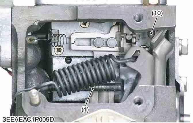
(b)Increase of fuel
9Y1211156ENM0004US0