4 minute read
4. FRONT LOADER CONTROL VALVE [1]


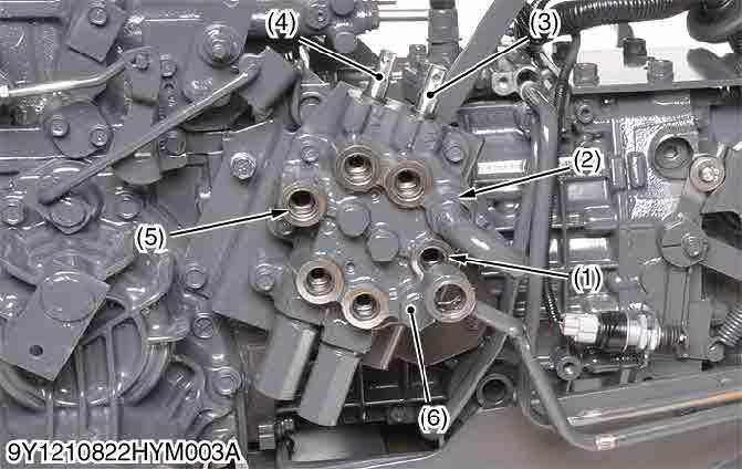
Structure
The control valve assembly consists of one casting block and four major section as shown above.
1)Inlet and Outlet Section
This section has P and T ports.
The P port is connected to the OUTLET port of hydraulic block by the hydraulic hose.
The T port is connected to the TANK port of hydraulic block by the hydraulic hose.
2)Boom Control Section
The boom control valve is consists of 4-position, 6-connection, detent, spring center type, consisting of a mono block valve housing, spool, load check valve, etc. This valve has A1 and B1 ports and controls oil flow to the boom cylinder.
3)Bucket Control Section
The bucket control valve is consists of 4-position, 6-connection, no detent, spring center type, consisting of a mono block valve housing, spool, load check valve, etc. This valve has A2 and B2 ports and controls oil flow to the bucket cylinder.
4)Power Beyond
This section has PB port which is connected to the INLET port of hydraulic block by the hydraulic hose, and feeds oil to the 3-point hitch hydraulic control valve.
(1)Pump Port
(2)Tank Port
(3)Boom Control Spool
(4)Bucket Control Spool
(5)Power Beyond Port
(6)Loader Valve Assembly
9Y1211156HYM0011US0
9Y1211156HYM0012US0
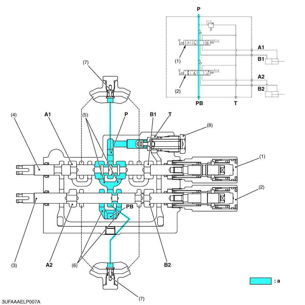
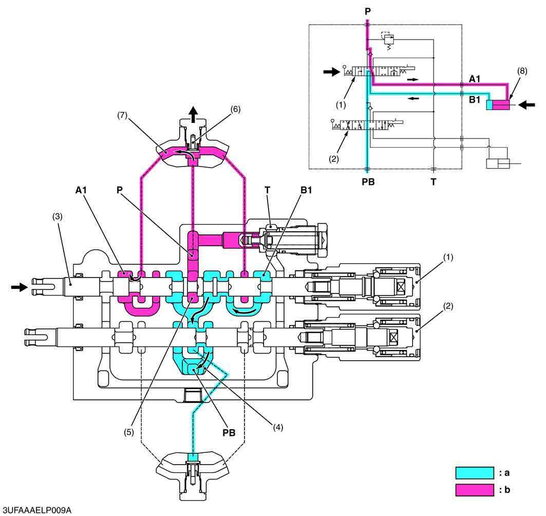
1.When the hydraulic control lever is set to the "UP" position, the spool (3) of the boom control section (1) moves to the left, which forms oil passages between passage 1 (7) and B1 port, and between A1 port and PB passage 1 (4).
2.As the oil passage from the neutral passage 1 (5) to the PB passage 1 (4) is closed by the spool (3), the pressure-fed oil from the P port opens the load check valve (6) and flows through the notched section of the spool (3) and B1 port to extend the boom cylinder (8).
3.Return oil from the boom cylinder (8) flows from the A1 port through the passage in the spool (3) and PB passage 1 (4) to the bucket control section (2).
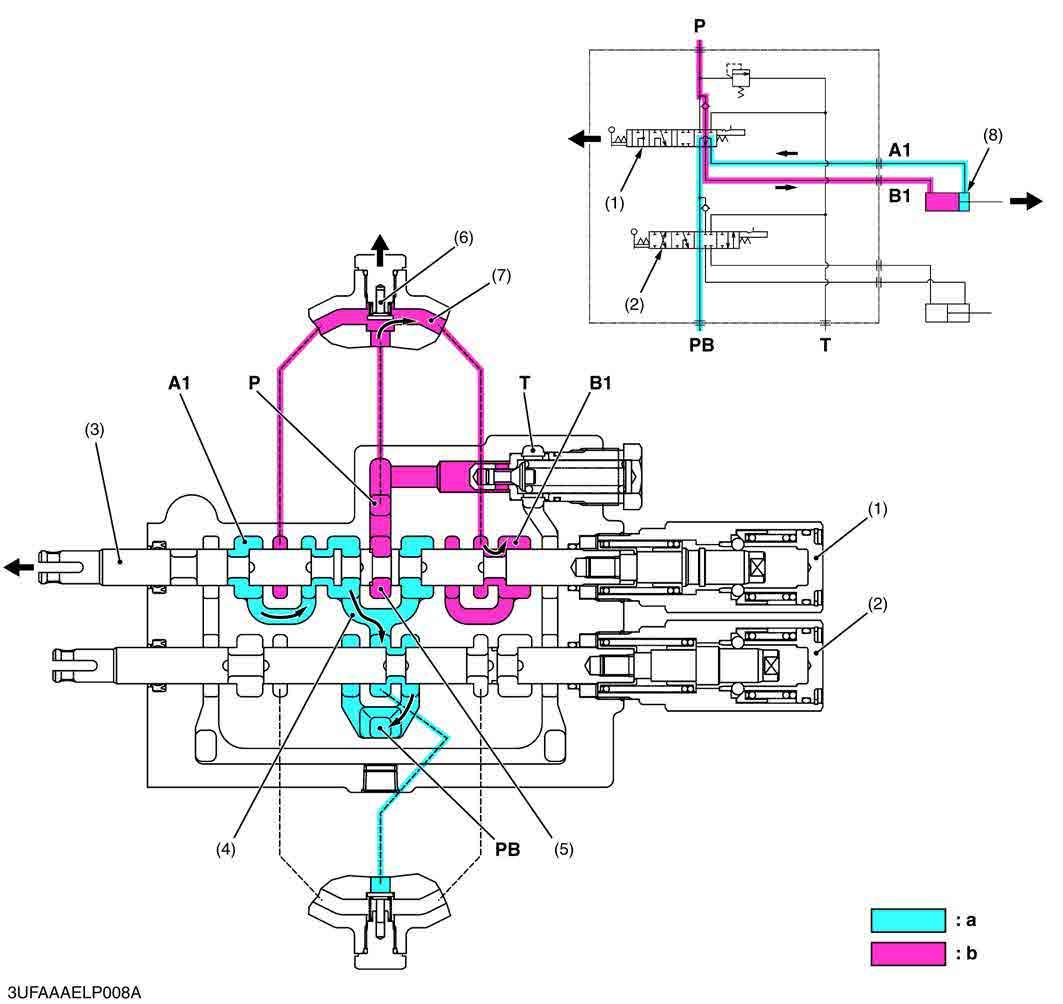
1.When the hydraulic control lever is set to the "DOWN" position, the spool (3) moves to the right, which forms oil passages between passage 1 (7) and A1 port, and between B1 port and PB passage 1 (4).
2.As the oil passage from the neutral passage 1 (5) to the PB passage 1 (4) is closed by the spool (3), the pressure-fed oil from the P port opens the load check valve (6) and flows through the notched section of the spool (3) and A1 port to retract the boom cylinder (8).
3.Return oil from the boom cylinder (8) flows from the B1 port through the passage in the spool (3) and PB passage 1 (4) to the bucket control section (2).
9Y1211156HYM0014US0
1.When the hydraulic control lever is set to the "FLOAT" position, the spool (3) moves further to the right from the "DOWN" position and is retained by the detent mechanism (5).
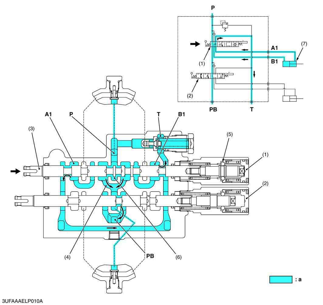
2.This forms oil passages among the A1 port, B1 port and T port. As a result, oil in the boom cylinder (7) flows freely from the A1 port and B1 port through the T port to the transmission case.
3.Oil entering the P port flows to the bucket control section (2) through the neutral passage 1 (6) and PB passage 1 (4).
Roll-back
(1)Boom Control Section
(2)Bucket Control Section
(3) PB Passage 1
(4)Spool
(5)Neutral Passage 2
(6) PB Passage 2
(7)Load Check Valve
(8)Passage 2
(9)Bucket Cylinder
P:P Port
T:T Port
PB:PB Port
A2:A2 Port (From Bucket Cylinder)
B2:B2 Port
(To Bucket Cylinder) a:Low Pressure b:High Pressure
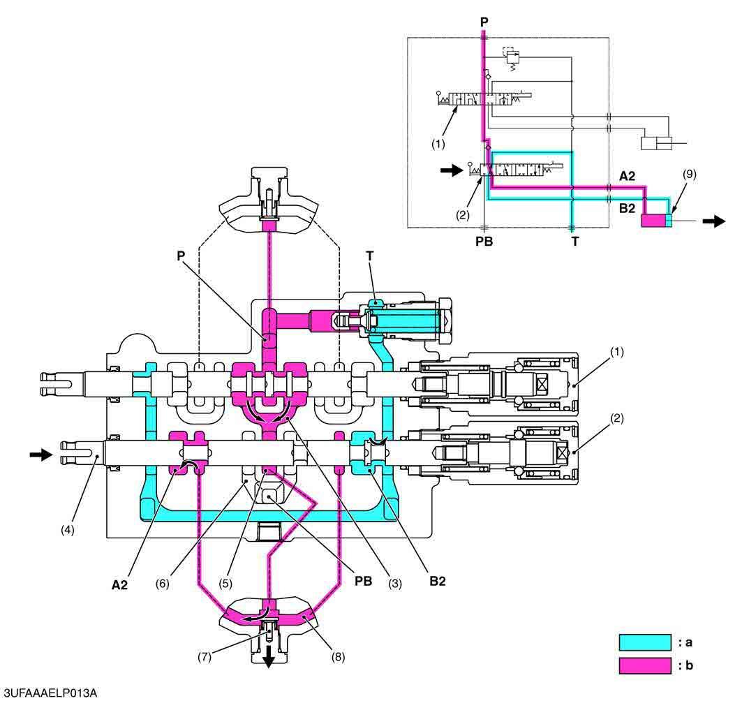
1.When the hydraulic control lever is set to the "ROLL-BACK" position, the spool (4) of the bucket control section (2) moves to the left, which forms oil passages between passage 2 (8) and B2 port, and between A2 port and T port.
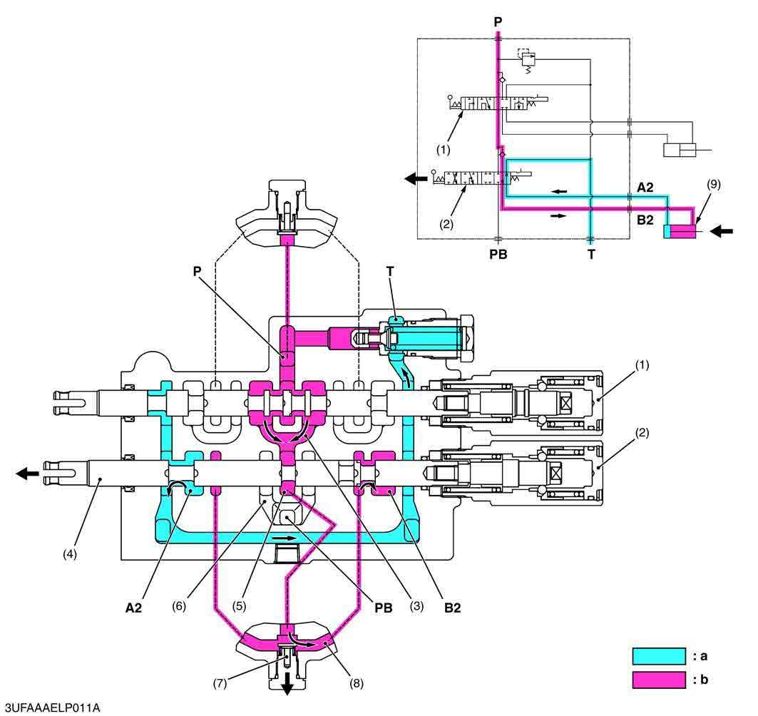
2.The pressure-fed oil from the P port flows to the neutral passage 2 (5) through the boom control section (1) and PB passage 1 (3). As the oil passage from the neutral passage 2 (5) to the PB passage 2 (6) is closed by the spool (4), this oil opens the load check valve (7), and flows through the notched section of the spool (4) and B2 port to retract the bucket cylinder (9).
3.Return oil from the bucket cylinder (9) flows to the transmission case through the A2 port and T port.
9Y1211156HYM0016US0
Dump 1
1.When the hydraulic control lever is set to the "DUMP 1" position, the spool (4), which forms oil passages among passage 2 (8), A2 port and B2 port.
2.The pressure-fed oil from the P port flows through the boom control valve, opens the load check valve, and flows to the bucket cylinder to extend the cylinder through the notched section of the spool and A2 port.
3.Return oil from the bucket cylinder (9) flows from the B2 port to the passage 2 (8), and flows to the A2 port together with the pressure-fed oil from the P port. As a result, the dump speed is increased.
(Reference)
•The oil pressure of the A2 port and B2 port is identical, but the bucket cylinder extend by the difference of received pressure area (cylinder rod part).
Dump 2
(1)Boom Control Section
(2)Bucket Control Section
(3) PB Passage 1
(4)Spool
(5)Neutral Passage 2
(6) PB Passage 2
(7)Load Check Valve
(8)Passage 2
(9)Bucket Cylinder
A2:A2 Port (To Bucket Cylinder)
B2:B2 Port
(From Bucket Cylinder) a:Low Pressure b:High Pressure
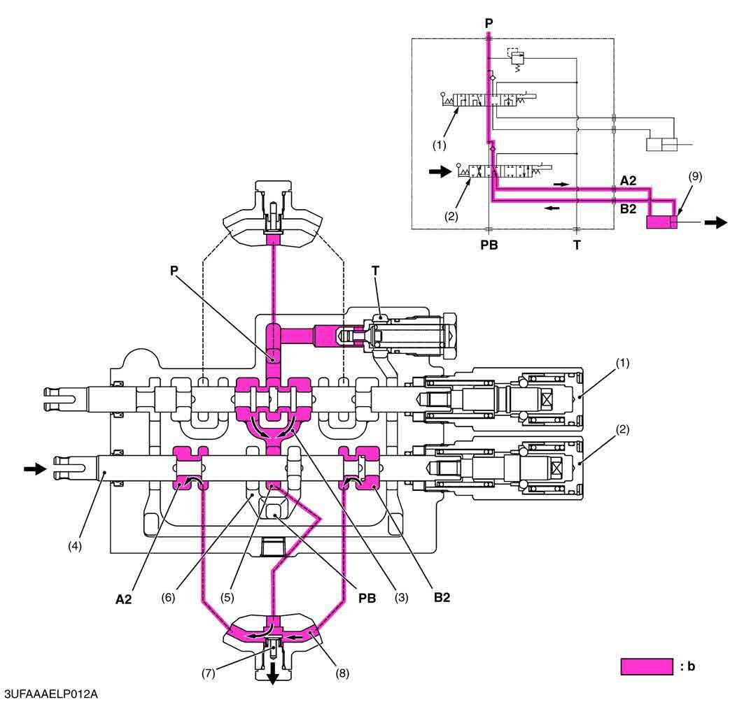
1.When the hydraulic control lever is set to the "DUMP 2" position, the spool (4) of the bucket control section (2) moves to the right of the bucket control section (2) moves further to the right from the "DUMP 1" position, which forms oil passages between passage 2 (8) and A2 port, and between B2 port and T port.
2.The pressure-fed oil from the P port flows to the neutral passage 2 (5) through the boom control section (1) and PB passage 1 (3). As the oil passage from the neutral passage 2 (5) to the PB passage 2 (6) is closed by the spool (4), this oil opens the load check valve (7) and flows through the notched section of the spool (4) and B2 port to extend the bucket cylinder (9).
3.Return oil from the bucket cylinder (9) flows to the transmission case through the B2 port and T port.
9Y1211156HYM0018US0