HYDRAULIC SYSTEM
B2301, B2601, WSM
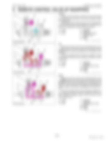
5. REMOTE CONTROL VALVE (IF EQUIPPED) Neutral Pressure-fed oil from the hydraulic pump is delivered into the P port, and flows to the rear hydraulic outlet through BY port. At this time, oil from A port to the T port is blocked by the mechanical check valve (Poppet (1)). Therefore the position of implement is kept at the set position. (1) Poppet (2) Piston (3) Spool
P: Pump Port T: Tank Port BY: BY Port (To Position Control Valve) A: A Port B: B Port 9Y1211156HYM0019US0
Lift When the remote control valve operating lever is set to LIFT position, the spool (3) moves to the right and the passage from P port to the BY port is blocked by the spool (3). Then the pressure-fed oil open the poppet (1) and flow through the A port to the hydraulic cylinder to lift the implement. (1) Poppet (2) Piston (3) Spool
P: T:
Pump Port Tank Port (To Transmission Case) BY: BY Port A: A Port B: B Port 9Y1211156HYM0020US0
Down When the remote control valve operating lever is set to DOWN position, the spool (3) moves to the left and the passage from P port to the BY port is blocked by the spool (3). At the same time, the piston (2) and poppet (1) moves upward, and open the passage from A port to T port. Then the pressure-fed oil flow through the B port to the hydraulic cylinder to lower the implement. Return oil from hydraulic cylinder flows from A port to the transmission case. (1) Poppet (2) Piston (3) Spool
P: T:
Pump Port Tank Port (To Transmission Case) BY: BY Port A: A Port B: B Port 9Y1211156HYM0021US0
7-M17
KiSC issued 11, 2014 A


