CHAPTER 14 SET-UP & ASSEMBLY The Baler is shipped with the following parts NOT attached to the Main unit:
3.
Install each of the (2) Bale Ramps to the Axle mounted Ramp Anchors securing each with (2) 1/2 x 1-1/4″ Cap Screws, Lock Washers and Nuts. Several mounting positions are available to allow compensation for various crop and field conditions.
4.
Roll the Ramp Shields over the Ramps and secure each using a Hold Down Strap, (2) 1/2 x 1-1/4″ Cap Screws, Lock Washers and Nuts.
– Wheels & Tires – Bale Ramp Shields (Quick Wrap Models) – Bale Ramps – Tractor Controls and Control Cables – Hose & Cable Support
WHEELS & TIRES The Baler may be shipped from the factory without Wheels and Tires mounted. Install the Tires and Rims; torque the Wheel Nuts to 90 ft-lb (124 N-m). Inflate the Tires to 40 PSI (280 kPa). Refer to the Wheels & Tires topic at the end of the Service chapter for additional information.
7 6
2
3
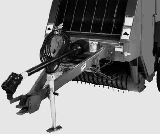
IMPLEMENT PTO Installation of the PTO is covered in the Preparing for Field Operation chapter.
3 5
BALE RAMPS (Fig. 128) The Bale Ramps and mounting hardware are packed loose in the Twine Box. Install each of the (2) Bale Ramps to the Axle mounted Ramp Anchors securing each with (4) 1/2 x 1-1/4″ Cap Screws, Lock Washers and Nuts. Several mounting positions are available to allow compensation for various crop and field conditions.
1.
Remove the (4) 1/2 x 5″ Cap Screws and 1/2″ Lock Nuts that secure the (2) Ramp Anchor Assemblies and retain.
2.
Install a Ramp Shield to the back of each Ramp Anchor Assembly securing with the retained (4) 1/2 x 5″ Cap Screws, 1/2″ Lock Nuts and adding (4) 1/2″ Flat Washers as shown in Fig. 128.
907520/CP0600
6
7
9 8
1 1 – Ramp (2) 2 – Ramp Shield (2) 3 – Hold Down Strap 4 – 1/2 x 5″ Cap Screw (4) 5 – 1/2 Lock Nut (4) 6 – Flat Washer (4) 7 – 1/2 x 1-1/4″ Cap Screw (8) 8 – Lock Washer (8) 9 – Nut (8)
BALE RAMP SHIELDS & BALE RAMPS (QUICK WRAP MODELS ONLY) (Fig. 128) The Bale Ramp Shields and mounting hardware are packed loose in the Twine Box. Installation is as follows:
4
Fig. 128
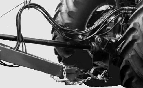
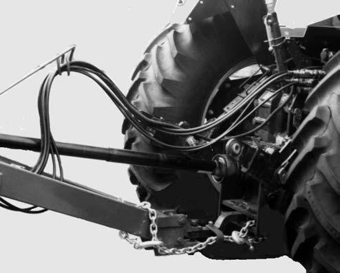
HOSE & CABLE SUPPORT Attach the Hose & Cable Support to the right front face of the Hitch securing with (2) 5/8 x 2″ Cap Screws, (2) 5/8″ Flat Washers and Lock Washers. MAKE SURE to place the Flat Washers under the heads of the Cap Screws. Route the Hydraulic Hoses, Transport Lighting Cable and Baler Control Cable through the loop on the Hose & Cable Support.
NOTE: To ease assembly, manually extend the Twine Arm for additional clearance. 128
Printed in U.S.A.