6 minute read
PREPARING FOR FIELD OPERATION


Preparing The Material
Material to be baled should be clean and dry. Wet material will cause overloading in the Baler resulting in high Side Sheet resistance, wrapping on the Rollers and high Belt tension. In addition to baling problems, wet material when baled will have a tendency to spoil easier as well as be more prone to spontaneous combustion.
Hay being prepared for round baling should be windrowed into a 45″ or 24″ (1143 or 610 mm) windrow for the RB1475 or, 61″ or 36″ (1549 or 914 mm) windrow for the RB1875 Baler. Corn stalks should be severed from their roots. Corn stalks, straw and other brittle materials should be raked into a full-width windrow, since these materials tend to break-up and deteriorate due to Side Sheet friction. In addition, the wider windrow will reduce crop loss or trash build-up.
NOTE: Improper windrow widths result in barrel-shaped bales because of material overlap in the center of the bale. Narrow windrow widths will require a weaving path across the windrow to assure even crop distribution as the bale is formed.
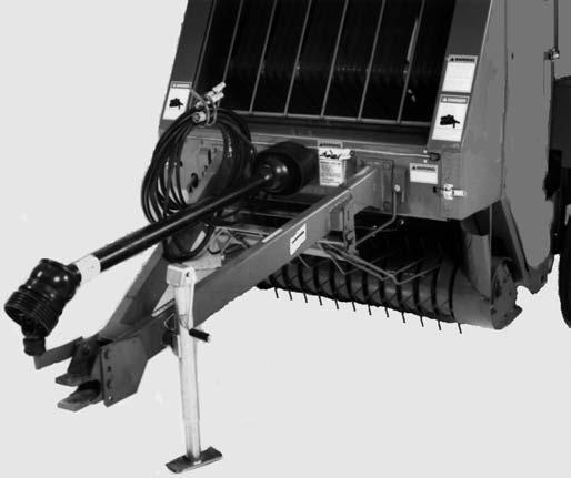
TRACTOR REQUIREMENTS & HITCH CONNECTIONS (Figs. 115 & 116)
Tractor
The Round Baler MUST be operated by a tractor with the following:
1.A minimum power output of 50 hp (37 kW) (RB1475) and 60 hp (45 kW)(RB1875) for level ground or 70 hp (52 kW)(RB1475) and 75 hp (56 kW)(RB1875) for hilly terrain or high density bales.
2.Having NON-tricycle type front wheels.
3.Having a minimum rear wheel inside dimension 45″ (RB1475) or 61″ (RB1875).
4.Equipped with a PTO which runs at 540 RPM with a standard 1-3/8″ 6-tooth spline (1000 RPM optional conversion is available).
5.Equipped with at least one set of double acting hydraulic outputs to operate Gate Cylinders.
6.Having standard PTO and hitch dimensions conforming to ASAE Standard S203, as shown.
Figure 115 shows one of the two possible mounting positions for tractors with drawbars having 13 to 17″ (330 to 432 mm) high ground clearance. Figure 116 shows one of the two possible mounting positions for tractors with drawbars having a ground clearance greater than 17″ (432 mm) high.
Warning
NEVER connect a 1000 RPM tractor to a baler equipped for a 540 RPM PTO drive.
Warning
Because dry material is being processed, the tractor should also be equipped with a spark arrestor muffler, if the tractor emits sparks.
IMPORTANT: If this unit is connected to a tractor equipped with a Hammer Strap style drawbar, the Hammer Strap parts shown in dashed lines MUST be removed to prevent damage to the unit Driveline. See Fig. 114 for details.
1 – Tractor PTO Shaft*
2 – 15-1/2″ (394 mm) for 540 Operation (17″, 432 mm, 1000 RPM)(Measured from retaining groove in tractor PTO to center of Hitch Bolt)
3 – 6 to 12″ (150 to 300 mm)*
4 – 13 to 17″ (330 to 432 mm) From Ground
5 – Locking Hitch Bolt (Provided)
*Tractor MUST comply with ASAE Standard S203
Fig. 115: Drawbar Hitchplate in “Low”
Mounting Position (For tractors with 13 to 17″ (330 to 432 mm) drawbar ground clearance
Drawbar Connection
When hooking the Baler to the tractor drawbar, BE SURE to use the Bolt, Nut and Hairpin Cotterpin provided. To prevent the bolt from becoming an obstacle to hay movement, insert the bolt from the bottom side of the tongue. Install the Hairpin Cotterpin after the Nut is secured. The proper Baler-tractor hook-up will NOT only allow maximum ground clearance but will also insure that the Baler will NOT become detached from the tractor.
DRAWBAR FLAP (Fig. 117)
If the Baler Drawbar is catching and bunching up the windrow below the Hitch, order and install a Drawbar Flap (420-34054) to help eliminate the problem.
1 – Tractor PTO Shaft*
2 – 15-1/2″ (394 mm) for 540 Operation (17″, 432 mm, 1000 RPM)(Measured from retaining groove in tractor PTO to center of Hitch Bolt)
3 – 6 to 12″ (150 to 300 mm)*
4 – 17 to 21″ (432 to 535 mm) From Ground
5 – Locking Hitch Bolt (Provided)
*Tractor MUST comply with ASAE Standard S203
Fig. 116: Drawbar Hitchplate in “High”
Mounting Position (Tractors with greater than 17″ (432 mm) drawbar ground clearance
1
1 – Drawbar Flap (420-34054)
Fig. 117
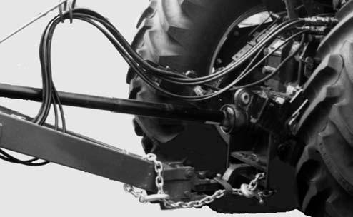
PTO CONNECTION (Figs. 115–119)
Warning
DO NOT start the tractor until the locking device is positively engaged to hold the telescoping drive couplings onto the tractor pto shaft and baler transmission input shaft. Also, BE SURE that the drive shafts rotate freely inside the drive shield tubes.
The Baler is equipped with a Constant Velocity Telescoping PTO Drive Shaft. This constant velocity capability, while cornering, results in a smooth, quiet running Drive Line, without power fluctuation.
NOTE: Whether in operation or NOT, the Maximum Joint angle MUST NOT exceed 80°. Any angle, greater than 80°, WILL result in damage to the Joint. In addition, for continuous operation, the maximum Joint angle should be limited to 35° Wide-angle Constant Velocity Joints are NOT designed for use as angled-gearboxes. Any continuous operation, at angles greater than 35°, will result in shortening Joint life.
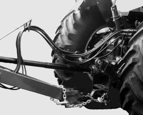
HYDRAULIC CONNECTIONS (Fig. 119)
The Hoses for the Hydraulic Gate Cylinders are equipped with Pioneer ASAE S366.1 (SAE J1036, ISO 5675) quick-disconnect couplers. The Baler is delivered already primed with Type F Automatic Transmission Fluid (ATF) in the Gate Cylinder control hydraulic system. This should be changed if this is incompatible with your tractor hydraulic fluid. BE CAREFUL when handling the Hoses and fittings to insure that they are kept free of dirt and contamination to avoid damage to the Baler and/or tractor hydraulic system.
NOTE: The Baler comes with the Rear Gate Cylinder system filled with Hydraulic Transmission Fluid. MAKE SURE this fluid is compatible with your tractor’s hydraulic system BEFORE connecting to the tractor. If the fluid is NOT compatible, the system will have to be drained and refilled with the fluid used in your tractor.
TWINE ROUTING (Figs. 120 thru 124)
To thread the Baler with twine, proceed as follows: NOTE: Use the following twine routing procedure from each Twinebox through the Twine Tubes in the Baler Frame.

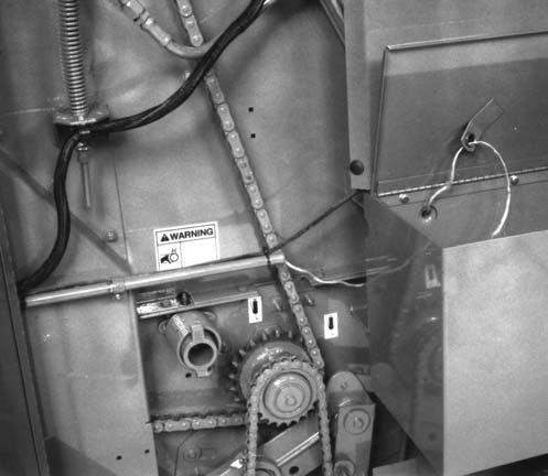
1.Place up to three balls of twine in the Twinebox. If continuous feeding is desired, route the twine end through the Guide above the twine ball on the Twinebox Cover, tie the twine ends together (always tie the outside twine end of the first ball to the inside twine end of the next ball for continuous feeding). On each side of the Baler, pull the end of twine from the center of the first ball and out through the hole in the side of the Twinebox.
NOTE: The characteristics of the wrapping materials used to wrap bales varies significantly. Therefore, the way in which the twine is routed around the Twine Wheels (or through the Rope Guides on Manual Tie Models) is important. To achieve optimum placement of the wrapping material on the bale. The plastic material should be wrapped around the Twine Wheels 1-1/2 times. The sisal style twine works best with a 1/2 wrap around the Twine Wheel. However, if the Twine Wheel appears to be slipping, 1-1/2 wraps around the Twine Wheel should be considered.
NOTE: The Twine Keeper is to be adjusted so the Tab of the Keeper rests on the Twine Guide while the outside corners of the Twine Keeper are flush with the outside edges of the Twine Wheels. The Twine Keeper is to be centered between the flanges of the Twine Wheel.
3.On RB1475 Model Balers, proceed routing the twine through the two Rope Guides on the front center of the Hitch and into one of the two Tubes on the Twine Arm.
On RB1875 Model Balers, proceed routing the twine through the two upper Rope Guides on the front of the Hitch and into the one Rope Guide on the lower front of the Hitch. Continue into one of the two Tubes on the Twine Arm.

4.After the twine is through the Twine Arm, pull some twine from the Twine Arm to make sure it is dispensing freely and NOT hanging up. Cut off any excess twine which is extending from the Twine Arm more than 12″ (305 mm).
NOTE: After the first bale has been tied, the twine (extending from the Twine Arm) will be held by the Clamp Jaws, after cutoff. The Clamp Jaws should provide a 20″ (508 mm) tail of twine for starting to wrap the next bale.
START-UP
Warning
BE SURE all bystanders are away from the baler, all tools and other objects have been removed from the baler and the windrow is clear of all obstacles BEFORE proceeding. In addition, BE SURE that the PTO shafts turn freely inside their shield tubes before starting the tractor.
After the Baler is properly hooked up, start the tractor and run the PTO at a slow tractor RPM. Raise and lower the Rear Gate a few times to purge the hydraulic system of air and to make sure the Rear Gate opens and closes freely.