18 minute read
CHAPTER 14 SET-UP & ASSEMBLY


The Baler is shipped with the following parts NOT attached to the Main unit:
–Wheels & Tires
–Bale Ramp Shields (Quick Wrap Models)
–Bale Ramps
–Tractor Controls and Control Cables
–Hose & Cable Support
WHEELS & TIRES
The Baler may be shipped from the factory without Wheels and Tires mounted. Install the Tires and Rims; torque the Wheel Nuts to 90 ft-lb (124 N-m). Inflate the Tires to 40 PSI (280 kPa). Refer to the Wheels & Tires topic at the end of the Service chapter for additional information.
Implement Pto
Installation of the PTO is covered in the Preparing for Field Operation chapter.
BALE RAMPS (Fig. 128)
The Bale Ramps and mounting hardware are packed loose in the Twine Box. Install each of the (2) Bale Ramps to the Axle mounted Ramp Anchors securing each with (4) 1/2 x 1-1/4″ Cap Screws, Lock Washers and Nuts. Several mounting positions are available to allow compensation for various crop and field conditions.
BALE RAMP SHIELDS & BALE RAMPS (QUICK WRAP MODELS ONLY) (Fig. 128)
The Bale Ramp Shields and mounting hardware are packed loose in the Twine Box. Installation is as follows:
1.Remove the (4) 1/2 x 5″ Cap Screws and 1/2″ Lock Nuts that secure the (2) Ramp Anchor Assemblies and retain.
2.Install a Ramp Shield to the back of each Ramp Anchor Assembly securing with the retained (4) 1/2 x 5″ Cap Screws, 1/2″ Lock Nuts and adding (4) 1/2″ Flat Washers as shown in Fig. 128.
3.Install each of the (2) Bale Ramps to the Axle mounted Ramp Anchors securing each with (2) 1/2 x 1-1/4″ Cap Screws,Lock Washers andNuts. Several mounting positions are available to allow compensation for various crop and field conditions.
4.Roll the Ramp Shields over the Ramps and secure each using a Hold Down Strap, (2) 1/2 x 1-1/4″ Cap Screws,Lock Washers andNuts.
1 – Ramp (2)
2 – Ramp Shield (2)
3 – Hold Down Strap
4 – 1/2 x 5″ Cap Screw (4)
5 – 1/2 Lock Nut (4)
6 – Flat Washer (4)
7 – 1/2 x 1-1/4″ Cap Screw (8)
8 – Lock Washer (8)
9 – Nut (8)
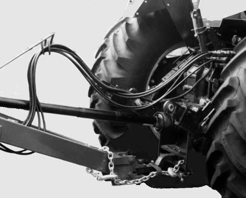
HOSE & CABLE SUPPORT
Attach the Hose & Cable Support to the right front face of the Hitch securing with (2) 5/8 x 2″ Cap Screws, (2) 5/8″ Flat Washers and Lock Washers. MAKE SURE to place the Flat Washers under the heads of the Cap Screws. Route the Hydraulic Hoses, Transport Lighting Cable and Baler Control Cable through the loop on the Hose & Cable Support.
NOTE: To ease assembly, manually extend the Twine Arm for additional clearance.
Twine Tie Systems
NOTE: The Twine Arm and Actuator comes fully assembled and mounted on the Baler from the factory.
Manual Twine Wrap System (Fig. 129)
Tractor Control Box Installation
A Bracket is provided for attaching the Receptacle onto the tractor. The Bracket should be located on the rear of the tractor in a position which prevents the Cable from being caught by the PTO.
Appropriate hardware and mounting brackets are provided for attaching the Control Box to a non-supportive member (such as the cab or a fender) on the tractor. BE SURE to locate the Control Box within convenient reach. Make the Red (+) 12-volt and White (-) 12-volt tractor battery/ground connections for powering the Control Box. A 20 amp Bus Bar connection is also acceptable. Any intermediate wire or harness must be AWG 10 gauge or heavier.
Bale Counter Installation
1.Pop rivet the Bale Counter to the Counter Mounting Bracket using the Pop Rivets supplied.
2.Attach one end of the Extension Spring to the Bale Counter Arm closing the loop in the Spring to secure.
3.Mount the Counter Assembly to the TDC Valve Trip Mechanism using the existing hardware on the Baler (TDC Valve Trip Stop Bolt & TDC Valve Mounting Bolt).
4.Loosen the TDC Valve Trip Mounting Bolt. Attach the other end of the Extension Spring to the end of the Bolt facing the front of the Baler and secure.
Baler Actuator Cable Installation
1.Remove Windguard to gain access to the Twine Arm Actuator.
2.Route Actuator Cable through Cable and Hose Support, along Hydraulic Hoses, through the Hitch Assembly and plugging into the Actuator. Secure the Cable with the Cable Ties provided.
Caution
DO NOT secure cable to any moving parts or pinch points.
3.Replace Windguard.
Automatic Twine Wrap System (Figs. 130 – 133)
1.Connect the Power Harness to an adequate power source that is capable of supplying a minimum of 20 Amps at 12 Volts. Connect the RED power lead to the (+) polarity of the power source and the BLACK power lead to the (–) polarity (Ground).
Tractor Control Box Installation
NOTE: If the RED power lead is connected to the wrong polarity, the system will NOT respond.
2.Avoid using an intermediate harness or wiring means between the power source and the Power Harness supplied with your Gehl Baler.
3.An inline fuse holder is manufactured into the RED (+) positive lead of the Power Harness. The holder has a 20 Amp spade type automotive fuse inside. For replacement use an equivalent 20 Amp fuse.
4.Route the Power Harness in such a way as to be protected by its location, but so it does not interfere with any other tractor controls or moving parts. Route the female connector end of the Harness to the tractor and plug the connector into the bottom of the Control Box. Route the bracket and male connector assembly to the rear of the tractor. Mount the bracket securely to the back of the trac- tor in a location that will keep and hold the power cord in a safe operating position.
Baler Shuttle Position/Bale Size Sensor Installation (See
Fig. 130)
1.Mount the Shuttle Position/Bale Size Sensor on the two rear upper Tie Rods of the left TDC Cylinder securing with two 1/2″ Hex Nuts. MAKE SURE to position the Sensor Assembly so the Sensor is facing down or towards the rear of the machine.
2.Remove the special Screw, Lock Washer and Flat Washers that retain the Sprocket Assembly at the top of the left TDC Cylinder. Place the Slide Mounting Plate over the exposed Pin and secure with the removed hardware deleting one of the Flat Washers.
3.Pre–assemble the Slide, Strap, Magnet Assemblies, Magnet Nuts and Nylon Washers as shown.
4.Route the Slide Assembly through the Shuttle Position/Bale Size Sensor and secure the Assembly to the outside of the Plate on the top of the TDC Cylinder clevis with a 3/8 x 1″ Cap Screw and 3/8″ Nylon Insert Lock Nut. Adjust the Magnet Assembly in the Slide to determine bale size. Move the Magnet closer to the sensor for smaller bales and farther from the Sensor for larger bales.
Baler Tailgate Sensor Installation (See Fig. 130)
1.Remove the Nut and Lock Washer from the two lower Gate Stop mounting Bolts on the left side of the Baler.
2.Mount the Tailgate Sensor Assembly as shown securing with the two lower Gate Stop mounting Bolts. The Assembly has Weld Nuts for the Bolts.
Baler End Wrap Pause Sensor Installation (See Fig. 131)
1.Remove Windguard to gain access to the Twine Tie Assembly.
2.Install Pause Sensor Assembly on Twine Tie Frame as shown securing with (2) 5/16 x 1″ Cap Screws, (4) 5/16″ Flat Washers and (2) 5/16″ Lock Nuts.
NOTE: The Pause Sensor Cam MUST pass between Magnet and Sensor without touching the Magnet or Sensor.
Baler Cable Installation (See Fig. 130)
1.Route Implement Cable through Cable and Hose Support, along Hydraulic Hoses, through the Hitch Assembly and connect the Actuator leg (white & yellow wires) of the Cable into the Actuator. Also connect the End Wrap Pause leg (brown & green wires) to the End Wrap Pause Sensor.
2.Continue routing the Implement Cable through the left side of the Hitch Assembly, along the Twine Tube and to the remaining Sensors. The Connector with the grey & green wires goes to the Gate Latch Sensor and the Connector with the blue & green wires goes to the Shuttle Position/ Bale Size Sensor.
3.Secure the Implement Harness with the Wire Ties & Clamps as shown.
4.Replace Windguard.
1 – To Tractor Power Harness
2 – To End of Wrap Pause Switch
3 – To Twine Arm Actuator
4 – To Shuttle Position Switch
5 – To Gate Latch Switch
Fig. 133: Implement Harness
AUTOMATIC BALE CONTROL SYSTEM (Figs. 134,
135 & 136)
3.Eight (8) Touch Keypads which are used singly or in pairs to perform specific functions
Implement Module
The Implement Module is factory installed on the left side of the Baler next to the TDC Cylinder. The Implement Module is:
1.A memory storage unit
2.The controller for the Tractor Module
3.A fully pre-programmed computer
4.The component from which the Wiring Harness extends
Tractor Module
The Tractor Module is part of a mounting and wiring package for the tractor. The Module and mounting and wiring package comprises:
1.A cooperating Microprocessor with the Implement Module
2.A Liquid Crystal Display (LCD) Indicator
4.Magnetic base male Spade Mount and Bracket for placement on tractor fender or other metal cab member within convenient operator arm’s reach
NOTE: If NO convenient metal member exists, remove Spade Mount and secure with field-supplied standard hardware. Remove protective cover from LCD Display by starting at one corner of the display and peel off plastic cover.
Power Harness
1.Connect the Power Harness to an adequate power source that is capable of supplying a minimum of 17 Amps at 12 Volts. The red power lead is to be connected to the (+) polarity of the power source, and the black power lead is to be connected to the (–) polarity (Ground)
2.Avoid using an intermediate harness or wiring means between the power source and the Power Harness supplied with your Gehl Baler
3.An inline fuse holder is manufactured into the (+) positive lead of the Power Harness (See Item 2,
Fig. 134). The holder should have a 20 Amp spade type automotive fuse inside. For replacement use an equivalent 20 Amp fuse.
NOTE: Do NOT reverse wiring connections because system will NOT respond.
4.Route the Power Harness in such a way as to be protected by its location, but not in interference with any other tractor controls or moving parts.
The rectangular connector with the four wires is to be routed to the operator’s station and plugged into the back of the Tractor Module. The bracket with the round 6-pin connector is to be routed to the back of the tractor. The bracket should be mounted securely to the back of the tractor in a location that will keep and hold the power cord in a safe operating position.
Pin Identifications
Pin Wire Description
A1 Ground Black
A2 Twine Actuator (Yellow)
A3 Net Actuator
B1 Ground (Gate Latch - Black)
B2 Ground Gate Latch & Pinch Roll Return (Black)
B3 Bale Size Sensor +V (Red)
B4 Bale Size Sensor, Signal (Orange)
C1 Ground (Black)
C2 Left Twine Sensor (White)
D1 NOT Used
D2 Right Twine Sensor (Green)
D3 Pinch Roll Count (Violet)
D4 Shuttle Return (Pink)
G1 NOT Used
G2 Gate Latch Switch (Gray)
H1 Ground, Shuttle Return (Black)
H2 Serial Communication A. (Blue)
J1 Bale Size Sensor, Ground (Black)
J2 Left Twine Sensor Return (Black)
J3 End Wrap Pause (Brown)
J4 Serial Communication B. (Yellow)
K1 +12 Volts D.C. (Red)
K2 Twine Actuator (Red)
K3 Net Actuator (Red)
Plug Identifications
Pin Wire Description
B3 Bale Size Sensor +V (Red)
B4 Bale Size Sensor, Signal (Orange)
J1 Bale Size Sensor, Ground (Black)
K1 +12 Volts D.C. (Red)
A1 Ground Black
C2 Left Twine Sensor (White)
D2 Right Twine Sensor (Green)
J2 Left Twine Sensor Return (Black)
G2 Gate Latch Switch (Gray)
B1 Ground (Gate Latch - Black)
J3 End Wrap Pause (Brown)
C1 Ground (Black)
D3 Pinch Roll Count (Violet)
B2 Ground Gate Latch & Pinch Roll Return (Black)
H2 Serial Communication A. (Blue)
J4 Serial Communication B. (Yellow)
K2 Twine Actuator (Red)
A2 Twine Actuator (Yellow)
K3 Net Actuator (Red)
A3 Net Actuator
D4 Shuttle Return (Pink)
H1 Ground, Shuttle Return (Black)
CHAPTER 15 OPTIONAL FEATURES & ACCESSORIES
General Information
The following Optional Features & Accessories are available for installation on a Baler to increase its capabilities. Set-up and assembly information for all Kits, except the Twine Tie Mechanisms, are provided in separate instructions packaged with each Kit of parts.
1000 Rpm Conversion Kit
The 1000 RPM Conversion Kit (806698) will convert a standard 540 RPM RB1475 or RB1875 to 1000 RPM operation. The Kit includes a 1000 RPM Transmission, a tractor to implement PTO, 8 Shear Bolts, 2 Decals and an Instruction Sheet.
Belt Lacing Kit
The Belt Lacing Kit (802700) contains a 6″ (152.5 mm) wide Clipper Vice Lacer, (6) #4-1/2 Clipper Hook Cards and a 72″ (1829 mm) long piece of Nylon-coated Stainless Steel Cable. The Kit is required when it is necessary to repair a Baler Bale Forming Belt. Refer to details in the Service chapter of this manual for using the Kit.
BELT RE-LACING KIT
The Belt Re-lacing Kit (073390) contains the same components as the Belt Lacing Kit (802700) above with the exception of the Clipper Vice Lacer. This Kit is available to replace the supplies furnished with the above Kit.
Belt Lacing Cable
The Belt Lacing Cable (094104) is a 7″ (178 mm) long piece of Nylon-coated Stainless Steel Cable used for rethreading a Belt splice. Refer to the instructions in the Service chapter of this manual for using this Cable.
A 6′ (1.83 m) roll of Lacing Cable is also available by ordering part number 078112. Instructions are included.
Crowder Wheels Kit
The Crowder Wheels Kit (806492) is available for expanding the Pickup width of either model Baler to enable taking in a wider swath of material. The Kit contains (2) Crowder Wheels, Mounts and attaching hardware. Installation, operation and adjustment details are provided with the Kit of parts.
PACKING ROLLER LAGGING KIT (Fig. 137)
The Packing Roller Lagging Kit (068633) is available to improve feeding into the Baler in certain crop conditions. The Kit contains (2) Strips of Lagging (Belting), (36) Rivets and (4) Cover Strips. Installation details are provided with the package of parts.
1 – Lagging Strips
2 – Rivets (2 of 36)
3 – Cover Strips (2 of 4)
Fig. 137: Packing Roller Lagging Kit (Installed)
Pickup Hydraulic Lift Kit
The Pickup Hydraulic Lift Kit (806946) is available for remote height control of the Crop Pickup from the tractor. The Kit contains a Hydraulic Cylinder, hydraulic connections and mounting hardware. Installation details are provided with the Kit.
Shear Bolts
On 540 RPM model Balers, replacement Grade L9, 1/4 x 1-1/2″ Shear Bolts are available in packaged quantities of (8) per package by ordering part number 095141.
On 1000 RPM model Balers, replacement Grade 5, 1/4 x 1-1/2″ Shear Bolts are available in packaged quantities of (8) per package by ordering part number 900084.
Chevroned Belt Dutchman Kit
The Dutchman Kit (126230) contains (1) 36″ long, 6″ wide section of Chevron Belt, already laced and ready for splicing. Installation details are provided with the Kit.
Net Stripper Kit
The Net Stripper Kit (127038 - 1475 & 127039 - 1875) prevents the netting from following the belts up the backside of the Baler.
Chain Oiler Kit
The Chain Oiler Kit (806491) provides automatic oiling of all Drive Chains as the Baler is used. Installation details are provided with the Kit.
SAFETY CHAIN (Fig. 138)
The recommended Safety Chain for use with these Balers can be obtained in Kit 803320.
NOTE: If the Baler is to be transported on a public highway, a Safety Chain Kit should be obtained and installed following the details in the Transporting chapter.
Connector Kit 119923
This Connector Kit repairs the male and female ends of the Connectors (2 wires) that join the ends of the Baler Harness with the Left and Right Twine Feed Sensors, End Wrap Pause Sensor, Pinch Roll Count Sensor (Net Wrap models only) and the Shuttle Return & Full Size Bale Sensor on the Automatic Bale Control models. The Kit also repairs the Connectors for the End Wrap Pause Sensor, Gate Latch Sensor & Full Size Bale Sensor on the Automatic Twine Wrap models. Installation details are provided with the Kit.
Connector Kit 119924
This Connector Kit repairs the male and female ends of the Connectors (3 wires) that join the ends of the Baler Harness with the Bale Size Sensor. Installation details are provided with the Kit.
Connector Kit 119925
This Connector Kit repairs the male and female ends of the Connector (2 wires, 18 AWG blue and yellow) that joins the ends of the Baler Harness with the Implement Harness. Installation details are provided with the Kit.
Connector Kit 119926
This Kit repairs the 6 hole Connector to the Cab Module of the Auto–Electric Tie System in the tractor Power Harness. Installation details are provided with the Kit.
Connector Kit 119927
This Connector Kit repairs the male and female ends of the Connector (2 wires, 10 AWG red and black) that joins the ends of the Baler Harness with the Implement Harness. Installation details are provided with the Kit.
Connector Kit 119928
This Kit repairs the Fuse Holder in the tractor Power Harness on both Automatic Bale Control and Manual Twine Wrap models. Installation details are provided with the Kit.
Connector Kit 119929
This Connector Kit repairs the end of the Baler Harness (30 wire Connector) that plugs into the Implement Module. Installation details are provided with the Kit.
Contact Kit 141191
This Kit repairs the Contacts in the Plugs that join the tractor Power Harness to the Implement Harness on both Automatic Bale Control and Manual Twine Wrap models. The Kit also repairs the Contacts in the Plugs that join the tractor Power Harness to the Baler Control on the Manual Twine Wrap models. Installation details are provided with the Kit.
Connector Kit 141192
This Kit repairs the Plug (tractor half of Connector ONLY) that joins the tractor Power Harness to the Implement Harness on both Automatic Bale Control and Manual Twine Wrap models. The Kit also repairs the Plug in the Baler Control that plugs into the tractor Power Harness on Manual Twine Wrap models. Installation details are provided with the Kit.
Connector Kit 141193
This Kit repairs the Plug (Baler half of Connector ONLY) that joins Implement Harness to the tractor
Power Harness on both Automatic Bale Control and Manual Twine Wrap models. The Kit also repairs the Plug in the tractor Power Harness that plugs into the Baler Control on Manual Twine Wrap models. Installation details are provided with the Kit.
TWINE SENSOR JUMPER HARNESS 141460 (AUTOMATIC BALE CONTOL ONLY)
This Harness provides the necessary electrical connection to enable the Baler to be operated using just one string of twine on the Automatic Bale Control models.
2 MAGNET TWINE WHEEL 141532 (AUTOMATIC BALE CONTROL ONLY)
The 2 magnet Twine Wheel will speed up the twine tieing cycle. A Wheel MUST be ordered for each side of the Baler.
Chapter 16 Decal Locations
General Information
Decal Locations information is provided to assist in the proper selection and application of new decals, in the event the original decal(s) become(s) damaged or the machine is repainted. Refer to the listing for the illustration reference number, part number, description and quantity of each decal provided in the Kit. Refer to the appropriate illustration(s) for replacement location(s).
NOTE: Refer to the SAFETY Chapter of the Operator’s Manual for the specific information provided on all of the various Safety Decals furnished in the Decal Kit(s).
To insure proper selection for correct replacement decal(s), compare all of the various close-up location photographs to your machine BEFORE starting to refinish the unit. Then, circle each pictured decal (applicable to your machine) while checking off its part number in the listing. After you have verified all the decals needed for replacement, set aside unneeded decals for disposal.
New Decal Application
Surfaces MUST be free from dirt, dust, grease and other foreign material before applying the new decal. To apply a solid-formed decal, remove the smaller portion of the decal backing paper and apply this part of the exposed adhesive backing to the clean surface while maintaining proper position and alignment. Slowly peel off the other portion of the backing paper while applying hand pressure to smooth out the decal surface.
Caution
ALWAYS observe safety rules shown on decals. If decals become damaged, or if the unit is repainted, replace the decals. If repainting, BE SURE that ALL decals from the kit(s) which apply to your machine are affixed to your unit.
Paint Notice
Use this list to order paint for refinishing:
906315One Gal. AG Red
902872One Qt. Light Grey
9063166 (12 oz. Spray Cans) AG Red
9028746 (12 oz. Spray Cans) Light Grey
For a complete Decal Set, order Part Number 119614 for the RB1475 model Baler or 119615 for the RB1875 model Baler. The following Decals (as required) are included in the Sets:
Ref.Part No No.Description & Quantity
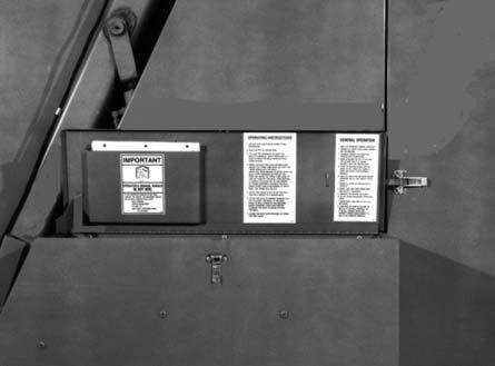
1060147Operating Instructions
2060148General Operating Instructions
3060151Shuttle Lock Position (2 Places)
4060510Jack Storage Position
5060511Jack Lifting Position
6061832Belt Tracking Adjustment (2 Places)
7067131Patent
8067493Red Reflector Strip (2 Places)
9091444DANGER - Rotating Drive Line
10093020Lubrication Symbol (16 Places)
11093366IMPORTANT - Store Manual Here
12093367WARNING - Owner’s Responsibility & Read Manual
13093373WARNING - General Safety
14093457WARNING - Keep Door Closed (3 Places)
15093458WARNING - Rotating Wrench
16093459WARNING - Reservoir Contamination
17093461DANGER - Belt Entanglement
18093462DANGER - No Manual Feed (2 Places)
19093466WARNING - 540 RPM Operation ONLY
20093653WARNING - Rotating Drive Line
21094914GEHL 5 x 23-1/2″ (Front)
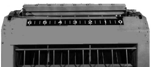
22094962Colorbar 13-1/2 (1 on Each Side)
23119562**Bale Size Indicator (1875 – 0-3)
119561**Bale Size Indicator (1875 – 4-6)
094977**Bale Size Indicator (1475)*
24112981Oil Level Indicator
25113340Reservoir Maintenance
261194461475
1194471875*
27119448TDC (1 on Each Side)
28119449High Moisture (Left Side)(1475 only)
119450High Moisture (Right Side)(1475 only)*
29141493Tailgate Lock
(After SN24715–1475 & SN17900-1875)
29119553Tailgate Lock (Before SN24716–1475 & SN17901-1875)
30119554DANGER - Moving Tailgate (2 Places)
31119596DANGER - Baler Entanglement (2 Places)
32122617GEHL (1 on Each Side)
33143007DANGER - PTO Shield (under Shield)
* Not Shown
** Automatic & Manual Twine Wrap Models Only
NOTE: Order Part Number 126757 for 10 ft roll of replacement Striping


NOTE: This following is a duplicated listing of the Decals from a previous page. It is provided for your convenience when selecting Decals from the second page of photographs.
For a complete Decal Set, order Part Number 119614 for the RB1475 model Baler or 119615 for the RB1875 model Baler. The following Decals (as required) are included in the Sets:
Ref.Part No No.Description & Quantity
1060147Operating Instructions
2060148General Operating Instructions
3060151Shuttle Lock Position (2 Places)
4060510Jack Storage Position
5060511Jack Lifting Position
6061832Belt Tracking Adjustment (2 Places)
7067131Patent
8067493Red Reflector Strip (2 Places)
9091444DANGER - Rotating Drive Line
10093020Lubrication Symbol (16 Places)
11093366IMPORTANT - Store Manual Here
12093367WARNING - Owner’s Responsibility & Read Manual
13093373WARNING - General Safety
14093457WARNING - Keep Door Closed (3 Places)
15093458WARNING - Rotating Wrench
16093459WARNING - Reservoir Contamination
17093461DANGER - Belt Entanglement
18093462DANGER - No Manual Feed (2 Places)
19093466WARNING - 540 RPM Operation ONLY
20093653WARNING - Rotating Drive Line
21094914GEHL 5 x 23-1/2″ (Front)
22094962Colorbar 13-1/2 (1 on Each Side)
23119562**Bale Size Indicator (1875 – 0-3)
119561**Bale Size Indicator (1875 – 4-6)
094977**Bale Size Indicator (1475)*
24112981Oil Level Indicator
25113340Reservoir Maintenance
261194461475
1194471875*
27119448TDC (1 on Each Side)
28119449High Moisture (Left Side)(1475 only)
119450High Moisture (Right Side)(1475 only)*
29141493Tailgate Lock (After SN24715–1475 & SN17900-1875)
119553Tailgate Lock (Before SN24716–1475 & SN17901-1875)
30119554DANGER - Moving Tailgate (2 Places)
31119596DANGER - Baler Entanglement (2 Places)
32122617GEHL (1 on Each Side)
33143007DANGER - PTO Shield (under Shield)
* Not Shown
** Automatic & Manual Twine Wrap Models Only
NOTE: Order Part Number 126757 for 10 ft roll of replacement Striping


Quick Wrap Decals
Individual Decal Sets for the QW1400 and QW1800 Quick Wraps are NOT available. Order Quick Wrap decals by individual part numbers.
1.047272Decal – SMV
2.093457WARNING – Moving Components (2 Places)
3.124982WARNING – Pinch Point
4.113151Decal – Net Instructions
Chapter 17 Maintenance Log
NOTE: Under extreme operating conditions more frequent service than the recommended intervals may be required. You must decide if your actual operation requires more frequent service based on your use.
Service Every 10 Hours
COMPONENT and SERVICE REQUIRED
PROCEDURE and/or CHAPTER TOPIC REFERENCE (Check Page No. in Index)
Inspect Upper Belts. Check Lacing and Pins.
Check Roller Chain Tension. See Chain Idlers topic in Adjustments chapter.
Lubricate Chains and appropriate grease fittings. Refer to Lubrication chapter for Grease Fitting locations and intervals.
TDC Reservoir air pressure & fluid level. Refer to Density Control system topic in Service chapter.
Date After Service is Completed
Service Every 50 Hours
Check Tire Pressure and Wheel Nut Torque. Inflate Tires to 40 PSIG (280 kPa) and torque Wheel Lugs to 90 ft-lb (124.5Nm).
Check Universal Drive Guards. Lubricate and test that Drive Shaft rotates freely inside Guard.
Inspect Twine Knife. Check sharpness – See Twine Knife topic in Service chapter.
Readjust Scraper position. Set up to Roller – See Scraper topic in Adjustments chapter.
Inspect Pickup Overfill Clutch. See Overfill Clutch topic in Adjustments chapter.
Inspect all Roller Bearings. Check for Seal failure & overheating.
Date After Service is Completed
Service Every 100 Hours
COMPONENT and SERVICE REQUIRED PROCEDURE and/or CHAPTER TOPIC REFERENCE (Check Page No. in Index)
Inspect Roller Chains and Drive Sprockets. Replace if worn more than 3% elongation.
Inspect Pickup Drive Belt. Replace if Belt NO longer drives Pickup.
Inspect Cams and Cam Bearings. See Pickup topic in Service chapter.
Check Packing Roller to 8″ Lower Roller clearance.
Readjust to 1/4″ (6 mm) clearance – see Packing Roller Clearance topic in Adjustments chapter.
Check quality and level of Transmission lubrication. Replace or replenish – see Lubrication chapter.
Date After Service is Completed
SERVICE EVERY 200 HOURS (OR END OF SEASON)
Inspect Universal Drive Joints. Refer if worn (loud and vibrating).
Inspect Universal Joint Seals. Replace if Seals worn or damaged.
Lubricate appropriate grease fittings and repack Wheel Bearings. Refer to Lubrication chapter.
Date After Service is Completed
Torque Specifications
NOTE: Use these torque values when tightening GEHL hardware (excluding: Locknuts and Self–tapping, Thread Forming and Sheet Metal Screws) unless specified otherwise.
All torque values are in Lb-Ft except those marked with an * which are Lb-In
(For metric torque value Nm, multiply Lb-Ft value by 1.355 or Lb-In value by 0.113)