20 minute read
AUTOMATIC TWINE WRAP SYSTEM TROUBLESHOOTING (Cont.)


Problem Cause Remedy
The word “tIE” is continuously displayed in the Control Box Digital Display while operating in the AUTO mode. (Continued)
Faulty Harness. Check for continuity in Harness.
Tie system will not start automatically.
End Wrap Pause Switch is faulty. Check for faulty End Wrap Pause Switch; Switch must close as the Magnet passes by.
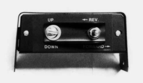
Mode Switch is set to MANUAL. Set Mode Switch Fig. 30, Ref. 1 to AUTO.
Trip Magnet is not activating the Bale Size Switch.
As the bale grows to the desired size, the Trip Magnet MUST slide within 1/8 inch (3.2 mm) of the Bale Size Switch (3/16–3/8 inch (4.8–9.5 mm) on Early Style Baler Control). If necessary, adjust Magnet to proper location in slot and make sure the Switch is mounted in the proper location. Refer to the Adjustments chapter.
Bale Size Switch is faulty. Check for faulty Bale Size Switch; Switch must close when the Magnet is near the Switch.
Tailgate OPEN/CLOSED Indicators do not function on Digital Display.
The Magnet on the Tailgate Switch Assembly is not properly adjusted.
Adjust the Magnet on the Tailgate Switch Assembly so that it passes within 3/32 inch (2.4 mm) from the Switch.
Tailgate Switch is faulty. Check for faulty Tailgate Switch; Switch must close as the Magnet passes by.
Tailgate “OPEN” “GATE” message continues to flash on Digital Display after a bale has been discharged.
The Magnet on the Tailgate Switch Assembly is not properly adjusted.
Adjust the Magnet on the Tailgate Switch Assembly so that it passes within 3/32 inch (2.4 mm) from the Switch.
Tailgate Switch is faulty. Check for faulty Tailgate Switch; Switch must close as the Magnet passes by.
Automatic Bale Control System Troubleshooting
NOTE: This Troubleshooting guide presents problems, causes and suggested remedies beyond the extent of loose, worn or missing parts and it was developed with the understanding that the machine is in otherwise good operating condition. BE SURE to exercise the MANDATORY SAFETY SHUTDOWN PROCEDURE (page 10), BEFORE making any adjustments or repairs.
Bale Wrapping Improperly
Problem Cause Remedy
Bale size is inconsistent.
Bale size sensor is not adjusted correctly (Fig. 83) or Jam Nuts are loose.
Friction Block not adjusted properly; too loose.
Cab Module display powers up for a few seconds and then shuts off.
Power is not reaching the Implement Module.
The air gap between the tip of the Bale Size Sensor to the Sprocket Tooth should be adjusted to 0.1 to 0.12″ (2.5 to 3 mm).
The Friction Block is to clamp on the sprocket Hub so as to create 3-4 in-lb (0.34–0.45 Nm) of drag when rotated up and down between stops.
The power cord between the tractor and the Baler is not properly connected.
Repair broken wire or poor connection between tractor power source and Implement Module.
Faulty Implement Module. See dealer.
System will not power up at all. Poor connection with Wiring Harness at tractor power source. Check for poor connections or broken wires in Power Harness.
Blown fuse in Baler power Harness. Replace with 20 amp automotive type fuse. Check for and repair any bare or broken wires in Harness.
BALE WRAPPING IMPROPERLY (cont.)
Problem Cause Remedy
The system starts before bale has reached programmed bale size.
Friction Block is not adjusted correctly. The Friction Block is to clamp on the Sprocket Hub so as to create 3-4 inlb (0.34–0.45 Nm) of drag when rotated up and down between stops.
Spacer/Magnet Assembly (located above left TDC Cylinder and to the rear of the Shuttle Return Switch) is set too close to Switch. Note: This assembly acts as an overall protection and starts the tie system before the Pickup assembly declutches
Clamp/Magnet Assembly located above left TDC Cylinder is not moving away from Shuttle Return Switch when TDC Cylinder is extended.
Spacer/Magnet Assembly (located above the left TDC Cylinder to the rear of the Shuttle Return Switch) is not moving away from the Shuttle Return Switch.
Refer to the Shuttle Return Switch topic in the Adjustments Chapter.
Clamp/Magnet Assembly is to be clamped on square tube and should require 4 lbs. (18 N) of force to slide on tube.
Free the Spacer/Magnet Assembly from the Shuttle Return Switch. The Spacer/Magnet Assembly should travel back and forth with the square tube located above the TDC Cylinder. The back and forth movement occurs as the TDC Cylinder Rod extends and retracts.
Shuttle Return Switch stuck in “closed” position.
To check for a faulty Shuttle Return Switch, separate Harness at Connector near the Switch. Check Switch continuity (using an ohmmeter or equivalent) by placing the tester leads on each Terminal of the Leads coming from the Switch. Whenever the Magnet in the mating part comes close to the Switch, the Switch should close. As the Magnet moves away from the Switch, the Switch should open.
Wires in Harness related to Shuttle Return Switch are short circuited.
Check Wiring Harness for bare wires. Separate Harness at Connector near Switch. With a volt/ ohmmeter check the voltage across the two Terminals in the Harness end of the Connector. When the Control System is on, the voltage should be 5 volts DC.
Error Message Explanations
One of the functions of the Tractor Module is to display the conditions of the Bale Wrap system, both in the stages of normal and proper operation and also in recognition of errors, failures and faults. Potential Error Message codes are listed in the beginning of this chapter.
E 1 - Out of Twine/Only One Twine on Bale (Twine Tie System ONLY)
Push ENTER to Silence Beeper
Twine Arm Stops at Right Side End Wrap Pause Position
Check for Cause of Error – See E1 Troubleshooting Guide
Feed in Small Amount of Crop to Get Twine Started
Reconnect PTO & Hydraulic Hoses, Restart Tractor Engine & Power-up Wrap Control System
If Wrap Material Starts, Resume Normal Operation
NOTE: The following information is developed in consideration of the Wrap System known to be correctly set up, properly wired and interconnected and operated in the “AUTOmatic” mode.
For whatever reason, if the Twine Wrap system twine runs out, an E1 error message will be given and the following action should be taken:
Exercise the MANDATORY SAFETY SHUTDOWN PROCEDURE ∗ & Power-down the Wrap Control System
Eject Bale Wrapped with Only One Twine & Continue Baling, if Desired
Push CYCLE to Repeat Tie Cycle
Push ENTER to Re-activate System
∗ Refer to SAFETY chapter of Baler Operator’s Manual for details.
E1 Troubleshooting Guide
1.Check twine supply and replenish if required.
2.Check if twine is broken, hooked, or pinched. Repair twine break and check to see if twine is routed properly.
3.Check that twine did not come off Twine Wheels. Reinstall if required. Adjust Twine Keeper, if required.
4.If E1 error is displayed just as Twine Arm comes to Home Position: a.The End Wrap Pause Switch is not adjusted correctly. Need to advance the Cam/Pause Plate. See the End Wrap Pause Switch topic in the Adjustments Chapter. b.Faulty End Wrap Pause Switch. To check for a faulty Switch, separate Harness at Connector near the Switch. Check the Switch continuity (using an ohmmeter or equivalent) by placing the tester leads on each Terminal of the Leads coming from the Switch. Whenever the Magnet in the mating part comes close to the Switch, the Switch should close. As the Magnet moves away from the Switch, the Switch should open. c.Check Wiring Harness for breaks or loose connections. Separate Harness at Connector near Switch. With a volt/ohmmeter, check the voltage across the two Terminals in the Harness end of the Connector. When the Control System is on, the voltage should be 5 volts DC.
E 2 - Out of Netting (Quick Wrap System ONLY)
Push ENTER to Silence Beeper
For whatever reason, if the Quick Wrap system netting runs out, the Actuator will return HOME and an E2 error message will be given. The following action should be taken:
Actuator returns to Home Position
Push CYCLE two times to find out the % of netting used from roll.
Check E2
Troubleshooting Guide
Reconnect PTO & Hydraulic Hoses & restart tractor engine & Power-up Wrap Control System
If new roll of netting is installed, reset % of Netting by pressing CYCLE two times; on second time, hold CYCLE for 5 seconds until “0” appears in display
Exercise the MANDATORY SAFETY SHUTDOWN PROCEDURE ∗ & Power-down the Wrap Control System
When netting starts, normal operation can be resumed
Push CYCLE to repeat Wrap Material feeding attempt
∗ Refer to SAFETY chapter of Baler Operator’s Manual for details.
∗∗As desired, attempt wrapping again or stop here and eject bale.
Push ENTER to Re-activate System
E2 Troubleshooting Guide
1.Check net supply and refill if required.
2.Check for torn netting: a.Brake is too tight. See operator‘s manual for brake adjustment. b.Netting is not routed properly. Check for proper net routing. c.Net roll does not rotate freely in storage position. Remove obstruction. d.Check for other foreign objects that might cause the roll of netting to rotate hard or not at all.
3.Pinch Count Switch and Magnet not functioning properly (Quick Wrap Only). Check the Pinch Count Switch located on the right side of the rubber Pinch Roller on the Quick Wrap. To check for a faulty Switch, separate Harness at Connector near the Switch. Check the Switch continuity (using an ohmmeter or equivalent) by placing the tester leads on each Terminal of the Leads coming from the Switch. Whenever the Magnet in the mating part comes close to the Switch, the Switch should close. As the Magnet moves away from the Switch, the Switch should open. The air gap between the plastic collar and the switch should be 1/16″ (1.6 mm).
4.Check Wiring Harness for breaks or loose connections. Separate Harness at Connector near Switch. With a volt/ohmmeter, check the voltage across the two Terminals in the Harness end of the Connector. When the Control System is on, the voltage should be 5 volts DC.
5.Replace any broken parts. Remove any obstacles and rethread the netting outlined in the procedure on the Decal provided on the Quick Wrap.
E 3 - Twine/Netting NOT Started
Push ENTER to Silence Beeper
The Circular CYCLE Light Will Continue to Flash for Approximately 15 Seconds OR Until Both Twines or the Netting Has Started Feeding on the Bale. If the Wrapping Material Does NOT Start and an E3 Error appears, the Actuator Will Return to the Home Position
CHECK E3 TROUBLESHOOTING GUIDE
Reconnect PTO & Hydraulic Hoses & restart tractor engine & Power-up Wrap Control System
Exercise the MANDATORY SAFETY
SHUTDOWN
PROCEDURE ∗ & Power down the Wrap Control System
Push CYCLE to repeat Wrap Material feeding attempt
Push ENTER to confirm cycle command
Push ENTER to Silence Beeper
If Wrap Material does NOT start, System will Time out & E3 Error will appear
CHECK E3 TROUBLESHOOTING GUIDE
For Twine Tie Systems only, the Tie System works best if the cycle is started with hay.
For Twine Tie System ONLY, feed in small amount of crop to try to get twine to start
If Wrap Material starts, normal operation can be resumed
∗ Refer to SAFETY chapter of Baler Operator’s Manual for details.
∗∗ As desired, attempt wrapping again or stop here and eject bale.
E3 Troubleshooting Guide
NOTE: E3 only appears if both twines or the net fail to wrap on the bale. System will successfully wrap bale with only one twine.
1.Check for depletion of wrapping material.
2.Wrapping material not routed correctly from storage location to discharge location. Check manual for correct routing.
3.Twine tail(s) not long enough (twine only). Check operator’s manual for correct twine jaw adjustment.
4.Net not starting (Quick Wrap Only). See Quick Wrap troubleshooting section.
5.Pinch Count Switch and Magnet not functioning properly (Quick Wrap Only). Check the Pinch Count Switch located on the right side of the rubber Pinch Roller on the Quick Wrap. To check for a faulty switch, separate Harness at Connector near the Switch. Check the Switch continuity (using an ohmmeter or equivalent) by placing the tester leads on each Terminal of the Leads coming from the Switch. Whenever the Magnet on the mating part comes close to the Switch, the Switch should close. As the Magnet moves away from the Switch, the Switch should open. The air gap between the plastic collar and the switch should be 1/16″ (1.6 mm).
6.Check Wiring Harness for breaks or loose connections. Separate Harness at Connector near Switch. With a volt/ohmmeter, check the voltage across the two Terminals in the Harness end of the Connector. When the Control System is on, the voltage should be 5 volts DC.
7.Both twines visually appear to be started but E3 reoccurs: a.Check that the twine has not jumped off the Twine Wheel. b.Check for faulty Twine Wheel Switch. Spinning both the Right and Left Twine Wheels independently by hand, should cause an E7 to appear on the Cab Module Display. If E7 does not occur, check for faulty Switch or missing Magnet in Twine Wheel. To check for a faulty Switch, separate Harness at Connector near the Switch. Check the Switch continuity (using an ohmmeter or equivalent) by placing the tester leads on each Terminal of the Leads coming from the Switch. Whenever the Magnet on the mating part comes close to the Switch, the Switch should close. As the Magnet moves away from the Switch, the Switch should open. c.Check Wiring Harness for breaks or loose connections. Separate Harness at Connector near Switch. With a volt/ohmmeter, check the voltage across the two Terminals in the Harness end of the Connector. When the Control System is on, the voltage should be 5 volts DC.
8.Bad wiring harness or poor connection: if both steps 5 and 6 check out OK, check out circuit for bare or broken wires or a loose connection.
9.Quick Wrap only. Check for trash in the net knife area. Also check that the Knife Carrier is being rotated away from the cutoff position and driving the Sprague Clutch. See net wrap troubleshooting section.
E 5 - Twine Arm Obstruction (Twine Tie System ONLY)
NOTE: Twine may or may NOT have started; Twine Arm may return HOME automatically depending on whether Arm was moving out from HOME or moving back to HOME.
Push ENTER to Silence Beeper
Manually return Twine Arm to Home Position
On a Twine Tie system only, an E5 error message could potentially occur, due to an obstruction in the path of the Twine Arm. The following action should be taken:
Exercise the MANDATORY SAFETY SHUTDOWN
PROCEDURE ∗ & Power-down the Wrap Control System
Check that twine is in the Clamps
Reconnect PTO & Hydraulic Hoses & restart tractor engine & Power-up Wrap Control System
Feed in small amount of crop to try to get twine to start
If Wrap Material starts, normal operation can be resumed
Push CYCLE to repeat Wrap Material feeding attempt
CHECK E5 TROUBLESHOOTING GUIDE
Push ENTER to confirm cycle command
∗ Refer to SAFETY chapter of Baler Operator’s Manual for details.
∗∗ As desired, attempt wrapping again or stop here and eject bale.
E5 Troubleshooting Guide
1.Check for and remove any visible obstructions.
2.If windrows are very large, the Windguard can be forced into the path of the Twine Arm. Slow down ground speed when full bale signal is given to reduce the amount of crop going into the baler.
3.If E5 is displayed when the Twine Arm travels completely to the left side of the baler without pausing and then returns home: a.The End Wrap Pause Switch is closing too late. See manual for End Wrap Pause Switch adjustment. b.End Wrap Pause Switch is sticking open. To check for a faulty Switch, separate Harness at Connector near the Switch. Check the Switch continuity (using an ohmmeter or equivalent) by placing the tester leads on each Terminal of the Leads coming from the Switch. Whenever Magnet on the mating part comes close to the Switch, the Switch should close. As the Magnet moves away from the Switch, the Switch should open. c.Check Wiring Harness for breaks or loose connections. Separate Harness at Connector near Switch. With a volt/ohmmeter, check the voltage across the two Terminals in the Harness end of the Connector. When the Control System is on, the voltage should be 5 volts DC. d.The gap between the End Wrap Pause Switch and magnet is too great. The air gap should be 1/16 to 3/32″ (1.6–3.2 mm). e.Twine Arm Stop Bolt (Fig. 66), used for stalling Actuator when applying end wraps to left side of bale, is extended out too far. The Twine Arm Linkage is striking the Stop Bolt before allowing Twine Arm to pause at pause position. f.Reset the Control System by disconnecting power to the Implement Module. This can be done by disconnecting the Power Chord between the Baler and tractor or by removing and reinserting the Fuse in the Baler Power Harness.
4.If E5 is displayed when Twine Arm stalls at Home Position: a.The End Wrap Pause Switch is opening too late. See manual for End Wrap Pause Switch adjustment. b.Faulty End Wrap Pause Switch. To check for a faulty Switch, separate Harness at Connector near the Switch. Check the Switch continuity (using an ohmmeter or equivalent) by placing the tester leads on each Terminal of the Leads coming from the Switch. Whenever the Magnet on the mating part comes close to the Switch, the Switch should close. As the Magnet moves away from the Switch, the Switch should open. c.Check Wiring Harness for breaks or loose connections. Separate Harness at Connector near Switch. With a volt/ohmmeter, check the voltage across the two Terminals in the Harness end of the Connector. When the Control System is on, the voltage should be 5 volts DC.
5.If E5 is displayed when Twine Arm stalls or hits an obstruction while in the extending mode: a.The Twine Arm will automatically return to Home Position. b.Exercise the Safety Shutdown and remove obstruction. c.Cycle tie system again.
NOTE: If Twine Arm encounters an obstruction between the pause position and the left side of the Baler, it will continue its normal wrapping operation. However, the left portion of the bale will not be wrapped. This is usually caused by crops being fed into the Baler too heavy while starting the twine. Slow down or stop ground speed when full bale signal is given.
6.If E5 is displayed when Twine Arm stalls while in retracting position: a.System switches to manual mode and Twine Arm remains where obstruction occurred. Operator may have to manually control the Twine Arm away from the obstruction. b.Remove obstruction. c.Return Twine Arm to Home Position.
E 6 - Shuttle NOT Returned
Push ENTER to Silence Beeper
If the Tailgate closes but the Shuttle does NOT return, the Wrap system will do a self-analysis and, after 7 seconds delay, an E6 error message will be given. The following action should be taken:
Push ENTER to Silence Beeper
To Clear E6 from Display, operate the tractor hydraulics to open the Baler Tailgate. Next, engage the PTO. Then, slowly close and Latch Tailgate.
Exercise the MANDATORY SAFETY SHUTDOWN PROCEDURE ∗ & Power-down the Wrap Control System
To Clear E6 from Display, operate the tractor hydraulics to open the Baler Tailgate. Next, engage the PTO. Then, slowly close and latch the Tailgate.
E6 Troubleshooting Guide
If the System beeps and the GO Arrow appears, normal operation can be resumed
If GO Arrow does NOT appear, continue with next steps.
Check E6
Troubleshooting Guide
The System should beep, the GO Arrow should appear and normal operation can be resumed.
Reconnect PTO & Hydraulic Hoses & restart tractor engine & Power-up Wrap Control System
∗ Refer to SAFETY chapter of Baler Operator’s Manual for details.
1.Check for twisted belts, or belt hooked on bale ramps.
2.Shuttle hanging up or shuttle locks engaged.
3.Check TDC system for correct air pressure and oil level. See manual for correct settings.
4.Check shuttle return switch so that trash is not obstructing the trip magnet.
5.Check that Friction Block with Magnet is properly positioned against Shuttle Switch.
6.Check for faulty Shuttle Return Switch. To check for a faulty Switch, separate Harness at Connector near the Switch. Check the Switch continuity (us- ing an ohmmeter or equivalent) by placing the tester leads on each Terminal of the Leads coming from the Switch. Whenever the Magnet in the mating part comes close to the Switch, the Switch should close. As the Magnet moves away from the Switch, the Switch should open.
7.Check Wiring Harness for breaks or loose connections. Separate Harness at Connector near Switch. With a volt/ohmmeter, check the voltage across the two Terminals in the Harness end of the Connector. When the Control System is on, the voltage should be 5 volts DC.
8.Control system was not powered down before interrupting electrical power to the Baler (ie. starting tractor). This is important if a partial bale is in the Baler.
E 7 - False Start for Wrap Material
NOTE: This error message may occur at any time during normal baling.
If the twine starts prior to the tie cycle, an E7 error message will be given. The following action should be taken:
Shut Off PTO
Push ENTER to Silence Beeper Exercise the MANDATORY SAFETY SHUTDOWN PROCEDURE ∗ & Power-down the Wrap Control System
For Twine Tie System ONLY, check that the twine is in the Clamps and check the Knife for frayed twine on the Knife
Power-up Wrap Control System
Inspect the System components making sure that the twine or netting is NOT wrapping on the Pickup, Rolls, Drive components or other areas. As necessary, remove any excess wrap material.
Reconnect PTO & Hydraulic Hoses & restart tractor engine
∗ Refer to SAFETY chapter of Baler Operator’s Manual for details.
∗∗As desired, resume baling or wrapping.
E7 Troubleshooting Guide
1.Inspect twine jaws to see if they are loose and working freely. (Twine Only)
Resume baling if error message does not reoccur
2.Be sure that twine is routed correctly.
E 8 - End Wrap Pause (EWP) Faulty or Misadjusted (Twine Tie System ONLY)
NOTE: When this error message occurs, the Twine Arm will return Home automatically.
Push ENTER to Silence Beeper Exercise the MANDATORY SAFETY
SHUTDOWN
On a Twine Tie system only, an E8 error message could potentially occur, due to the End Wrap Pause (EWP) Switch being out of adjustment or faulty. The following action should be taken:
Check E8
Twine Arm will return to Home Position
Detach and unplug the Screw Plug from the tractor harness to the Baler power cord. This is located at the rear of the tractor. This should reset the system parameters. Then, re-connect the Plug.
Feed in small amount of crop to get the twine to start. Then, resume normal baling.
PROCEDURE ∗ & Power-down the Wrap Control System
Reconnect PTO & Hydraulic Hoses & restart tractor engine & Power-up Wrap Control System
E8 Troubleshooting Guide
Troubleshooting Guide
Push ENTER to Re-activate System
∗ Refer to SAFETY chapter of Baler Operator’s Manual for details.
∗∗As desired, attempt wrapping again or stop here and eject bale.
1.If the Twine Arm hits an obstruction and stalls prior to the closing of the End Wrap Pause, an E8 will be displayed. Remove the obstruction.
2.E8 is displayed when Twine Arm travels uninterrupted to the left side of the Baler. The Switch is not closing due to misadjustment or a faulty Switch. To check for a faulty Switch, separate Harness at Connector near the Switch. Check the Switch continuity (using an ohmmeter or equivalent) by placing the tester leads on each Terminal of the Leads coming from the Switch. Whenever the Magnet in the mating part comes close to the Switch, the Switch should close. As the Magnet moves away from the Switch, the Switch should open.
3.Check Wiring Harness for breaks or loose connections. Separate Harness at Connector near Switch. With a volt/ohmmeter, check the voltage across the two Terminals in the Harness end of the Connector. When the Control System is on, the voltage should be 5 volts DC.
E 9 - Twine NOT Cut off (Twine Tie System ONLY)
Shut Off PTO
On a Twine Tie system only, an E9 error message will occur when the twine does NOT cut off. When this occurs, the following action should be taken:
Push ENTER to Silence Beeper Exercise the MANDATORY SAFETY SHUTDOWN
PROCEDURE ∗ & Power-down the Wrap Control System
Reconnect PTO & Hydraulic Hoses & restart tractor engine & Power-up Wrap Control System
If twine is NOT cut, inspect the Knife Clamps and Blade for frayed material, dull knife edge or improper clamp tension. Check if twine is in the twine clamp. If not, place in clamps.
∗ Refer to SAFETY chapter of Baler Operator’s Manual for details.
E 10 - Low Voltage/Low Amperage
The E10 Error Message usually occurs when the
Exercise the MANDATORY SAFETY SHUTDOWN PROCEDURE ∗ & Powerdown the Wrap Control System actuators are put in motion because of the additional current draw.
Check for Cause of Error and Correct Problem – See E10 Troubleshooting Guide
Restart Tractor Engine and Power Up the Control System
Press the MANUAL/AUTO Key to Switch to Manual Mode and then Press the ENTER Key
Manually Wrap the Bale
Push ENTER to Silence Beeper
Eject the Bale, Close the Tailgate and Wait for the “GO” Arrow
When “GO” Arrow Appears, Switch to the AUTO Mode
E10 Troubleshooting Guide
Press the MANUAL/AUTO Key and then the ENTER Key
1.Check for poor connection at power source.
2.Power harness for the control system is not connected to an adequate power source. Connect power harness directly to battery or power source that is capable of supplying 17 amps at 12 volts.
3.Using an intermediate harness or wiring between the power cord and the power source should be 10 gauge wiring or greater and capable of supplying 17 amps at 12 volts. If at all possible, an intermediate wiring harness should be avoided.
4.Check integrity of the tractor electrical system. If E10 appears while starting tractor engine, it may be an indication of battery weakening. Check water level in the batteries. Check wiring harness connections at power source for corrosion or poor connections. If problem persists, check charging system and battery strength.
QUICK WRAP (NET) SYSTEM TROUBLESHOOTING
NOTE: This Troubleshooting guide presents problems, causes and suggested remedies beyond the extent of loose, worn or missing parts and it was developed with the understanding that the machine is in otherwise good operating condition. BE SURE to exercise the MANDATORY SAFETY SHUTDOWN PROCEDURE (page 10), BEFORE making any adjustments or repairs.
Bale Wrapping Improperly
Problem Cause Remedy
The desired number of wraps is NOT being obtained.
The Drive Roller Switch is NOT operating correctly.
Check that Roller Switch closes when Magnet passes by.
The Drive Roller tension is incorrect. Readjust the Drive Roller tension.
Netting NOT started on Drive Rollers. Start netting on Roller per instructions on Decal.
Frequent bending of Feeder Fingers. Tailgate Roller too close to Floor Roller. Move Tailgate Roller back away from Floor Roller approximately 1-1/2″ (37 mm) from Tailgate Roller to the rib of the Floor Roller.
Feeder Fingers NOT adjusted properly. Readjust Feeder Finger positions with Baler empty and Gate against stops. Trash accumulation. Remove trash accumulated inside Bale Forming Belts before the bottom Tailgate Roller.
Bale is NOT being wrapped uniformly.
Foreign material or crop buildup on the Feeder Fingers. Remove any buildup and readjust the Finger positions, as required.
Belts NOT tracking correctly. Readjust the Belt tension and/or tracking per the information in this Supplement.
Rewrap Bar NOT locked down. Lock Bar in “DOWN” position.
An incorrect number of wraps is being placed on the bale. Readjust the wrap control to obtain at least two wraps.
Foreign material, crop or wrap material buildup on the Rollers or Belts.
Carefully and properly remove crop or wrap material from Rollers and/or readjust Feeder Belt tension, as required.
Netting NOT routed properly. Properly route Netting per instructions at the beginning of this Supplement.
The roll of Netting material is too narrow or of inadequate quality. Contact your Gehl dealer. Use ONLY Gehl approved wrap material.
Tear in the wrap material on bale. Rough edges or burrs on Tailgate Roller. File off rough edges.
Burrs on the Feeder Fingers. Remove the burrs with a file.
Rubber Ramp Shield NOT covering Bale Ramps. Reposition or replace Ramp Shield.
Feeder Finger snagging Netting when bale rolls out of Baler. Open Tailgate quicker.
BALE WRAPPING IMPROPERLY (cont.)
PROBLEM CAUSE REMEDY
Tear in the wrap material on bale (cont.).
Improperly adjusted or plugged Feeder Fingers. Readjust Feeder Finger positions.
Belts NOT tracking properly. Readjust Feeder Belt tracking or reinstall Feeder Fingers on left side of their mounting Tabs.
The Knife retracts to the “Cutoff” position but does NOT cut the material.
Netting follows Bale Forming Belts up the front of the Baler instead of wrapping Bale.
The Knife edge has become dull. Remove the Knife, sharpen it and replace it.
Lacing Cables exposed. Re-lace main Baler belts and replace any lacing hooks.
Blemish (cut or fray) in belt. Repair Belt. Add Net Stripping Kit, as described in Optional Features Chapter.
Bale Not Wrapped
PROBLEM CAUSE REMEDY
Feeder Belts stop turning or slip. Feeder Belt tension too loose. Readjust Feeder Belt tension.
Wrap material wraps around Drive Rollers.
Rear Net Guide too close to Rubber Drive Roller. Readjust Guide Roller.
Too much wrap material is being indexed into Net Chute when starting Net Roll.
Install the wrap material per the instructions on the Decal. BE SURE to avoid rotating the wrapping material Roll more than 1 revolution.
Pinch Rollers damaged. NEVER cut the Rubber Roller with a knife when attempting to remove wrapped material. Smooth off damaged areas with a file; it may be necessary to replace the Rubber Roller. Sticky material on Rubber Drive Roller. Clean the Roller.
Wrap material not reaching Bale at Lower Tailgate Roller.
Feeder Finger NOT properly adjusted. Readjust Feeder Finger positions. Trash accumulation. Remove trash accumulation inside Bale Forming Belts by bottom Tailgate Roller.